Wubster100
-
Posts
609 -
Joined
-
Last visited
-
Days Won
19
Content Type
Profiles
Forums
Gallery
Everything posted by Wubster100
-
 Between the 2007 and 2011 Ford Edge and the Lincoln MKX, there were significant electronic and communications system upgrades. Both model years use a combination of High-Speed (HS-CAN) and Medium-Speed (MS-CAN) Controller Area Networks. For Gen 1.5 in 2011, a new Infotainment CAN (I-CAN) was introduced to support the more advanced multimedia features. The 2007 Edge featured a simpler setup, with modules like the Audio Control Module (ACM), Instrument Cluster (IC), HVAC, and Smart Junction Box (SJB) on the MS-CAN, and safety-critical systems such as ABS, PCM, and the Restraints Control Module (RCM) on the HS-CAN. Optional modules included the DSP, parking sensors, and satellite radio. In contrast, the 2011 Edge added far more complexity and integration, especially with the introduction of the MyFord Touch system. The I-CAN network connected new modules like the Accessory Protocol Interface Module (APIM), Front Controls Interface Module (FCIM), and Front Control/Display Interface Module (FCDIM), enabling touchscreen control, voice commands, and smartphone integration. Additionally, the MS-CAN and HS-CAN networks expanded to include more sophisticated comfort and safety systems, such as the GPS module, heated steering wheel, blind spot detection (SOD-L/R), tire pressure monitoring (TPM), adaptive cruise control, and a head-up display (HUD) in certain trims. The 2011 model also transitioned to a more advanced Body Control Module (BCM) that replaced the earlier Smart Junction Box as a central gateway. These changes show a major upgrade in vehicle electronics, transforming the Edge from a traditional SUV with basic electronic systems in 2007 into a modern, digitally connected vehicle by 2011.
 -
Anything is possible if you swap enough parts over and put enough money and time into it. It will be difficult because you are working across 2 different generations (1 and 1.5): Gen 1: 2007-2010 Edge/MKX, Gen 1.5: 2011-2014 Edge, 2011-2015 MKX, Gen 2: 2015-2018 Edge, 2016-2018 MKX, Gen 2.5: 2019-2024 Edge/Nautilus Comparing the 2007 MKX to the 2011 MKX, there are some big changes in the communications network. Both vehicles have a HS-CAN and MS-CAN. The 2011 has a new I-CAN for the infotainment. Note: * = if equipped 2007 MS-CAN: Audio control module (ACM), *Dual climate controlled seat module (DCSM), *Driver seat module (DSM), *Audio digital signal processing (DSP), *Heating ventilation air conditioning (HVAC), Instrument cluster (IC) (gateway module), *Liftgate/trunk module (LTM), *Parking aid module (PAM), *Rear entertainment module (RETM), *Satellite digital audio receiver system (SDARS), Smart junction box (SJB). 2007 HS-CAN: ABS module, *Headlamp control module (HCM), Instrument cluster (IC) (gateway module), Occupant classification system module (OCSM), PCM, Restraints control module (RCM), *Steering angle sensor module (SASM), *4X4 control module 2011 I-CAN: *Accessory Protocol Interface Module (APIM), *Audio Digital Signal Processing (DSP), Front Controls Interface Module (FCIM), *Front Control/Display Interface Module (FCDIM), Instrument Panel Cluster (IPC) (gateway module) 2011 MS-CAN: *Accessory Protocol Interface Module (APIM), Body Control Module (BCM) (gateway), *Driver Seat Module (DSM), *Dual Climate Controlled Seat Module (DCSM), *Global Positioning System Module (GPSM), *Heated Steering Wheel Module (HSWM), HVAC, Liftgate/Trunk Module (LTM), *Remote Function Actuator (RFA), *Side Obstacle Detection Control Module - Left (SOD-L), *Side Obstacle Detection Control Module - Right (SOD-R), Tire Pressure Monitor (TPM) 2011 HS-CAN: *Accessory Protocol Interface Module (APIM), ABS module, Body Control Module (BCM) (gateway), *Cruise-Control Module (C-CM), *Front Lighting Control Module (FLM), *Headlamp Control Module (HCM), *Head Up Display (HUD), Instrument Panel Cluster (IPC) (gateway module), Occupant Classification System Module (OCSM), *Parking Aid Module (PAM), PCM, Restraints Control Module (RCM), Steering Column Control Module (SCCM)
-
Retrofit 360 Camera Into Ford Edge
Wubster100 replied to Wubster100's topic in Accessories & Modifications
The F-150 switch should be what we are looking for. Also note that the Explorer switch will not work. -
Ambient Lighting Finished! 💡
Wubster100 replied to Wubster100's topic in Accessories & Modifications
Looks amazing! My screen doesn’t have the graphic of the vehicle. I only have a toggle and brightness control.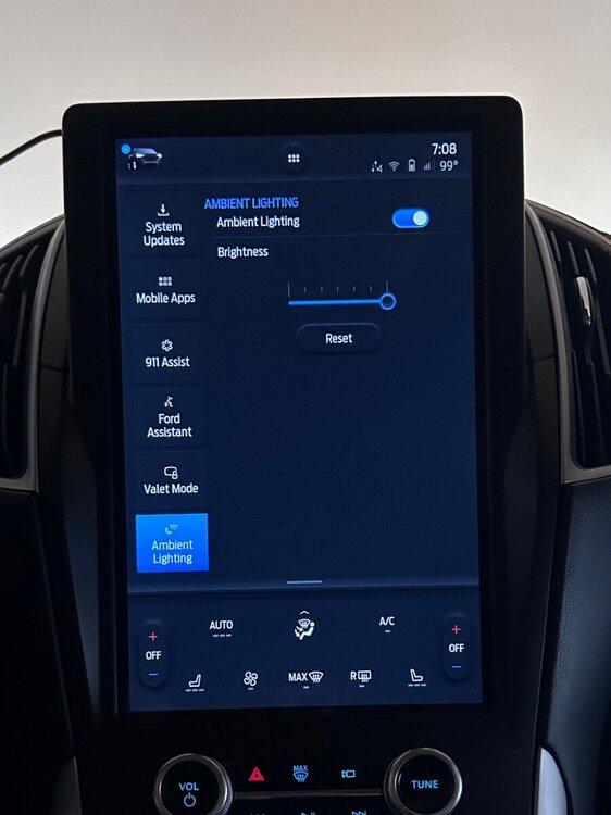
-
Instrument panel not responding.
Wubster100 replied to 2015 Greygoose's topic in Interior, A.C., Heat, Interior Trim
To get a better idea of what’s going on, could you share a few more details? What year is the Edge? What engine and trim is it (SE, SEL, Limited, etc.)? Do you know exactly what work the garage did before the problems started? Did the issues start right after picking it up, or was there a delay? When you say the instrument panel isn’t working, is it totally dead (no lights, gauges, warning lights), or are some parts still working? Any other electronics not working, like the radio, HVAC, headlights, etc.? You checked all the fuses visually? Did you test them with a multimeter or just look at them? Also, about the alternator, was it overcharging (15V seems a bit high)? Curious what made you decide to swap it out. -
I have thought about switching from ULV to LV, but I haven’t found enough solid research or firsthand experiences to know for sure whether it’s a good or bad move. In theory it would make things better? They are both low viscosity types, but ULV is designed to meet tighter tolerances and specific OEM requirements. Is it only for better fuel economy or is there something else at play? Without more data and real world feedback, I’m hesitant to make the switch and risk long term issues.
-
Retrofit 360 Camera Into Ford Edge
Wubster100 replied to Wubster100's topic in Accessories & Modifications
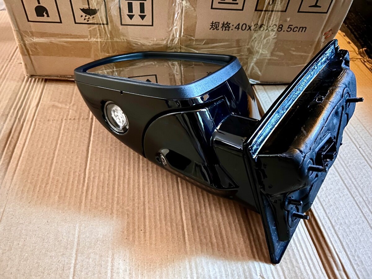
The Piglins were easy. It just takes some gold. The real challenge was trusting a $530 shipment from a Chinese auto parts dealer. But it actually came through. Not a bad price considering that used mirrors go for about $200 each. -
This is for all trim levels 2019-2024. Some vehicles are equipped with a PTU cooler.
-
Retrofit 360 Camera Into Ford Edge
Wubster100 replied to Wubster100's topic in Accessories & Modifications
My mirrors have arrived!
-
RDU: Motorcraft SAE 75W Disconnect RDU Fluid XY-75W-QL PTU: Motorcraft SAE 75W-85 Premium Synthetic Rear Axle Fluid XY-75W85-QL / WSS-M2C942-A ATF: Motorcraft MERCON ULV Automatic Transmission Fluid XT-12-QULV / WSS-M2C949-A / MERCON ULV
-
It looks like I am on 22028, so I still won’t be getting any updates for a while.
-
Does this mean that SYNC 3.4 will receive another update?
-
OEM Control Arms : revisions or supersessions
Wubster100 replied to razziel24's topic in Brakes, Chassis & Suspension
I have ordered a superseded part number for my rear wheel speed sensors because they were cheaper, and they are fine. The difficult part is figuring out what changes were made with the part revisions. -
OEM Control Arms : revisions or supersessions
Wubster100 replied to razziel24's topic in Brakes, Chassis & Suspension
The revision numbers may also indicate differences in the features of parts. As we see from this example, the audio control module KT4T-19C107-CE does not have active noise cancellation, while KT4T-19C107-DE does have active noise cancellation. https://www.fordedgeforum.com/topic/33925-active-noise-control-anc-retrofit-2019-titanium/ The best way to verify if a part will fit is to enter your vin number at parts.ford.com. -
Ford has disabled software updates for the computer in your infotainment system called the APIM (Accessory Protocol Interface Module). This is basically the computer that runs your SYNC 4 system (your touch screen, navigation, apps, etc.). If your vehicle's SYNC 4 software version is 23187 or older, your vehicle's infotainment system cannot currently be updated, not even by a Ford dealership. Ford made a technical decision to block updates for certain SYNC 4 systems. As of now, they haven’t explained why. Ford is expected to release more info or a fix later.
-
Is this the same issue as TSB-22-2404 that has been discontinued?
-
https://forscan.org/forum/viewtopic.php?f=13&t=18751 Also, you should be using a battery charger/maintainer (minimum 10 amps) to keep a stable voltage during programing. If the battery voltage drops too low, the firmware update can fail.
-
Yes, you need to update the firmware of the module.
-
Retrofit 360 Camera Into Ford Edge
Wubster100 replied to Wubster100's topic in Accessories & Modifications
So it looks like the Edge’s IPMB got moved from above the glove box to near the APIM area? It looks like the HVAC module is there instead of the IPMB. -
Do you have lane keep on? Do you see any lane keep indicators in the instrument cluster when it happens?
-
Retrofit 360 Camera Into Ford Edge
Wubster100 replied to Wubster100's topic in Accessories & Modifications
Nice diagram -
Heated and Cooled Seats
Wubster100 replied to Wedgeamatic's topic in Interior, A.C., Heat, Interior Trim
It is recommended to have a hardwired USB connection for flashing firmware and doing programming. USB is a more reliable connection than Bluetooth. A Bluetooth adapter should work well for diagnostic codes and simple programming. It may even work better in certain situations where you would want to move your computer around to different locations. -
Retrofit 360 Camera Into Ford Edge
Wubster100 replied to Wubster100's topic in Accessories & Modifications
Good idea. I already have the connectors and pins for the IPMB. -
Retrofit 360 Camera Into Ford Edge
Wubster100 replied to Wubster100's topic in Accessories & Modifications
@Haz can you post the connector pin out diagrams from the 2018 Ford Edge China of the door modules and right and left mirrors?
-
Heated and Cooled Seats
Wubster100 replied to Wedgeamatic's topic in Interior, A.C., Heat, Interior Trim
If you have a bad adapter, you will run into problems. Supported adapters: https://forscan.org/home.html OBDLink EX USB, recommended USB adapter for Windows version of FORScan, also for configuration and programming functions OBDLink MX+ BT, recommended Bluetooth adapter for Lite versions of FORScan (iOS, Android) OBDLink SX/LX/MX ELS27 (STN1170/2120) ELM327-compatible (fully compatible with original ELM327, please also see important note) J2534 Pass-Thru