

Wubster100
-
Posts
351 -
Joined
-
Last visited
-
Days Won
9
Content Type
Profiles
Forums
Gallery
Everything posted by Wubster100
-
I haven’t heard of any other Ford vehicles change their cruise control to not use the brakes.
-
I just tested my adaptive and regular cruise. You don’t even need to be on a hill, just set the cruise speed down lower. The vehicle applies the brakes in both regular and adaptive cruise. There were no vehicles in front or behind me when I tested. I set cruise around 40mph, and then I held the - button until the set speed went to 25mph. I can see the brake lights come on. The brake pedal feels slightly harder when the brakes are automatically being applied. I would love a way to get rid of this feature. Is it not a huge waste of gas? I want to be able to use hills to gain speed, and then only slow down if I get close to the vehicle in front. I have noticed that on the highways, faster like 70mph, if I go down a hill, my speed might rise above the set cruise speed by about 5mph. Is this why I will see random break lights on the highway for no reason?
-
I should find a steep hill and test my adaptive and regular cruise to see if I slow down. Too bad there isn’t an eco drive mode.
-
Overview The cruise control system is controlled by the PCM. The cruise control mode is selected from the steering wheel mounted switches which are integrated into the steering wheel. Refer to Owners Literature for additional information. The cruise control system maintains a selected vehicle speed between 32 kmh (20 mph) or 30 kmh (18 mph) (metric cluster) and the maximum limited vehicle speed. When a MyKey® restricted key is in use and maximum speed limiter is turned on, vehicle speed is limited to 129 kmh (80 mph). During normal driving, the vehicle speed can vary slightly from the set speed due to road conditions. The vehicle speed can fluctuate when driving up and down a steep hill. If the vehicle speed decreases more than 16 kmh (10 mph) below the set speed, the cruise control disengages. Cruise Control Operation The cruise control functions include: turning on the cruise control system. setting and maintaining the desired vehicle speed. accelerating the vehicle speed. coasting down to a lower speed. resuming the prior vehicle speed. turning off the cruise control system. The cruise control system maintains a selected vehicle speed within a range between 32 km/h (20 mph), or 30 km/h (18 mph) if equipped with a metric cluster, and the maximum limited vehicle speed. When a MyKey® restricted key is in use, the vehicle speed will not exceed the MyKey® maximum limited speed. During normal driving conditions, the vehicle speed can fluctuate slightly from the selected set speed due to road conditions. The vehicle speed can fluctuate more noticably when driving up and down steep hills. Certain conditions cause the cruise control system to deactivate: Application of the parking brake Transmission gear selector is placed into a position other than D or OD Cruise control set speed is overridden with the accelerator pedal for a period longer than 5 minutes Cruise control switch is pressed or stuck longer than 2 minutes Vehicle speed decreases more than 16 km/h (10 mph) below the set speed ABS fault The BPP switch assembly (contains the stoplamp switch and cruise control deactivator switch) and APP sensor are hardwired inputs to the PCM. Electronic Throttle Body (ETB) command is a hardwired output of the PCM. The vehicle speed is controlled by the PCM through the Electronic Throttle Control (ETC) subsystem. The cruise control system provides self-diagnostics. Cruise control is disabled anytime an error is detected in the system. No IPC indicator or message center messages are displayed when faults occur. Fault codes are logged by the PCM or SCCM. An Electronic Throttle Control (ETC) system fault also causes the cruise control system to be disabled. In this case, an Electronic Throttle Control (ETC) system powertrain malfunction (wrench) warning indicator is displayed.
-
Is it normal or adaptive cruise?
-
If you are going to replace your steering wheel, then you might as well look for one that is heated too.
-
Text sourced from @Haz Field Effect Transistor (FET) Protection The BCM utilizes an Field Effect Transistor (FET) protective circuit strategy for many of its outputs, for example, lamp output circuits. Output loads (current level) are monitored for excessive current (typically short circuits) and are shut down (turns off the voltage or ground provided by the module) when a fault event is detected. A Field Effect Transistor (FET) is a type of transistor that the control module software uses to control and monitor current flow on module outputs. The Field Effect Transistor (FET) protection strategy prevents module damage in the event of excessive current flow. Output loads (current level) are monitored for excessive current draw (typically short circuits). When a fault event is detected the Field Effect Transistor (FET) turns off and a short circuit DTC sets. The module resets the Field Effect Transistor (FET) protection and allows the circuit to function when the fault is corrected or the ignition state is cycled off and then back on. When the excessive circuit load occurs often enough, the module shuts down the output until a repair procedure is carried out. Each Field Effect Transistor (FET) protected circuit has three predefined levels of short circuit tolerance based on a module lifetime level of fault events based upon the durability of the Field Effect Transistor (FET). If the total tolerance level is determined to be 600 fault events, the three predefined levels would be 200, 400 and 600 fault events. When each level is reached, the DTC associated with the short circuit sets along with DTC U1000:00. These Diagnostic Trouble Codes (DTCs) can be cleared using the module on-demand self-test, then theClear DTC operation on the scan tool (if the on-demand test shows the fault corrected). The module never resets the fault event counter to zero and continues to advance the fault event counter as short circuit fault events occur. If the number of short circuit fault events reach the third level, then Diagnostic Trouble Codes (DTCs) U1000:00 and U3000:49 set along with the associated short circuit DTC . DTC U3000:49 cannot be cleared and the module must be replaced after the repair.
-

Edge ST 2022, Ambient light in the cupholder
Wubster100 replied to hsprime85's topic in Interior, A.C., Heat, Interior Trim
@HazThank you for the connector information. I was able to take connector C2280G apart and insert a wire into pin 13 (LIN bus). Pin 4 on connector C2280F (VPWR) looks to challenging to take apart, so I will look for +12v elsewhere. I connected power and LIN bus to my cup holder to test. Unfortunately, I was unable to get the cupholder to light up. And of course my multimeter also decided to not work! 😂 I think the battery is dead. I was able to get the ambient light menu in the settings screen. The BCM will be a little bit trickier because I haven't found a reliable source of information on the BCM AsBuilt Data. I need to do further research and investigation into the BCM. I would like to double check my wiring / new pin. Is there a way to test the connection to the LIN bus? Perhaps measuring the voltage or resistance of circuit VDN15 to confirm a good connection back to the BCM? -
2020 SEL - Where to penetrate the firewall?
Wubster100 replied to GhostRider's topic in Accessories & Modifications
The BCM with fuses isn't difficult to get to. It is by the driver's area. -
Edge ST 2022, Ambient light in the cupholder
Wubster100 replied to hsprime85's topic in Interior, A.C., Heat, Interior Trim
I got the cupholder with the ice blue ambient lights, but because of the LIN bus I have no way of powering the lights. Unfortunately, as I was checking the connectors on my BCM, I do not have any wiring for ambient lights. 😓 Pin 13 on connector C2280G (LIN bus for cup holder) doesn't look too difficult to add a wire onto. The more challenging connector looks like pin 4 on connector C2280F (VPWR). @HazThank you for the requested documents. Do you have a pinout for C2280F, as well as a service pigtail part / information for pin 4. -
Edge ST 2022, Ambient light in the cupholder
Wubster100 replied to hsprime85's topic in Interior, A.C., Heat, Interior Trim
@Haz Can you please provide a BCM pinout of the C2280D connector? -
Since you are not receiving any major DTCs and still receiving collision alerts, the CCM is probably still good. To calibrate the sensor, the vertical calibration is done by physically leveling the sensor. The horizontal calibration is done in FORScan. You just need it to point straight to the best of your ability. Calibration in FORScan is not required. When I got my CCM used, it didn’t need calibrated. Though, I would recommend calibrating the CCM if it gets moved at all. It is a simple process in FORScan, you only need to drive around for about 5-15 minutes and it will calibrate. I would recommend calibrating as the software is free and the cable is at a very reasonable price. The collision alerts will come from a combination of the CCM, and the IPMA camera and LiDAR system.
-
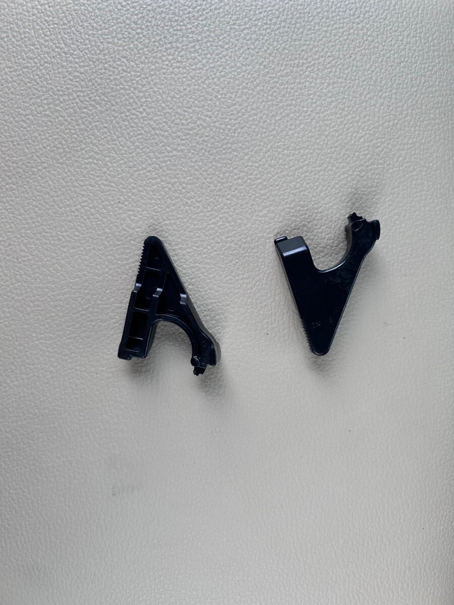
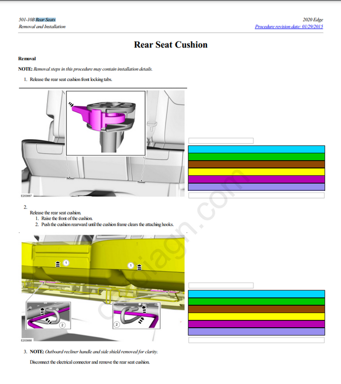
Rear Seat Cushion Loose 2015-2024
Wubster100 replied to Wubster100's topic in Interior, A.C., Heat, Interior Trim
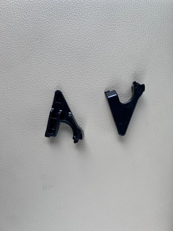
I might need to get 2 new clips.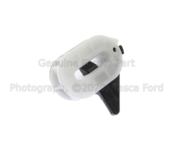
-
Rear Seat Cushion Loose 2015-2024
Wubster100 replied to Wubster100's topic in Interior, A.C., Heat, Interior Trim
Could the locking clips be broken? -
I am using SW-8183 (DG9Z-9C888-GC) This does not have lane centering. It has a LIM button but I haven't enabled it or tried to use it.
-
One of my passengers lost their airpod inside of the rear seat cushion where the seat belt latch is. We were able to remove the locking tab and lift the rear seat cushion up. Now, the rear seats are loose and I can't figure out how to lock them in place again.
-
AM Radio Reception 2015 Edge
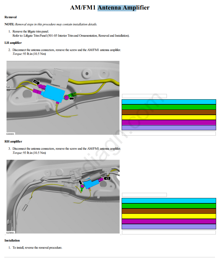
Wubster100 replied to Dmtaurus's topic in Audio, Backup, Navigation & SYNC
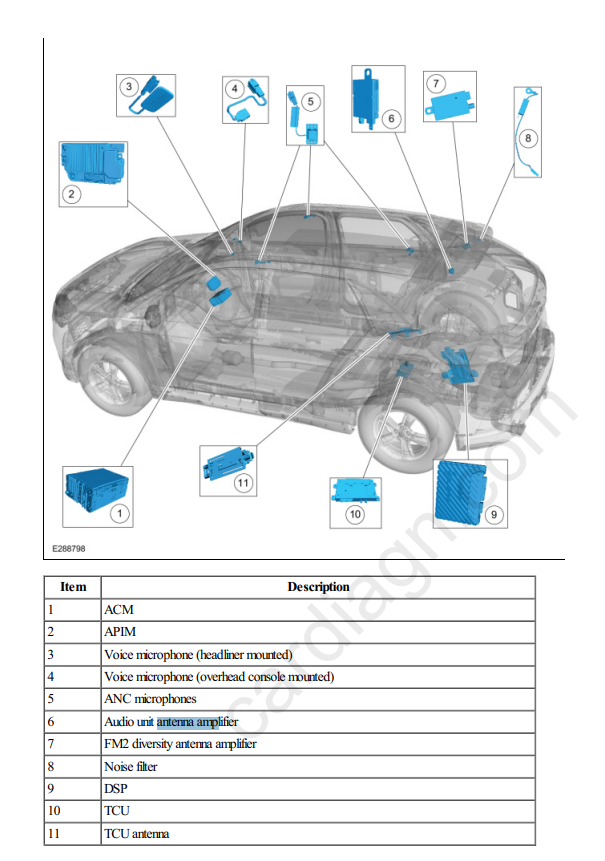
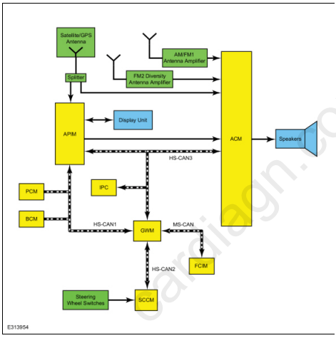
@Dmtaurus AM/ FM Radio When the AM/ FM mode is selected, the radio amplifies radio waves sent from the antenna. It then selects the requested frequency, converts and amplifies the content. These fluctuating audio signals are output as AC output voltage to power the speakers or as an input to a separate amplifier. If equipped with a FM2 diversity antenna, FM radio waves are collected and sent to be amplified by the FM2 diversity antenna amplifier. A coaxial antenna cable sends the amplified signal to the ACM. An ACM antenna signal comparator uses both antenna signals to reduce or eliminate FM distortion in poor signal environments. If equipped with HD Radio capability, the radio will automatically detect and playback the improved sound quality and multiple programs of HD broadcasts. AM/ FM1 Antenna The AM/ FM1 antenna (also called the audio unit antenna) is an on-glass antenna, mounted to the left side of the rear window. It receives AM/ FM radio waves and sends them through the audio unit antenna amplifier to the ACM via the audio unit antenna coaxial cable (also called the AM/ FM1 antenna coaxial cable). AM/ FM1 Antenna Amplifier The AM/ FM1 antenna amplifier (also called the audio unit antenna amplifier) amplifies AM/ FM radio signals to improve reception. The amplified signal is sent through a coaxial cable to the ACM. The amplifier is powered by the ACM through the coaxial cable. FM2 Diversity Antenna The FM2 diversity antenna is an on-glass antenna, mounted to the right side of the rear window. The FM2 diversity antenna improves FM reception in urban areas or anywhere large objects reflect FM signals and create multiple FM signal paths. FM2 Diversity Antenna Amplifier The FM2 diversity antenna amplifier amplifies FM radio signals and transmits them through a coaxial cable to the ACM. Voltage for the amplifier is provided by the ACM through the coaxial cable. GPS/Satellite Radio Antenna The GPS/satellite radio antenna contains a GPS antenna circuit board that receives radio waves containing GPS and satellite radio data (vehicles equipped with a satellite radio). The data is sent through the coaxial cable to the APIM ( GPS data) and through a splitter to the ACM (satellite radio data). Cellular Antenna If equipped, the audio unit antenna contains a cellular antenna circuit board that receives radio waves containing cellular data. The data is sent through the cellular antenna coaxial cable to the TCU. TCU Antenna The TCU antenna is used is used to boost reception for incoming and outgoing cellular network data. It is a compact, cellular phone type, planar inverted-F antenna


-
AM Radio Reception 2015 Edge
Wubster100 replied to Dmtaurus's topic in Audio, Backup, Navigation & SYNC
The "sail" on the roof is the satellite radio antenna. -
AM Radio Reception 2015 Edge
Wubster100 replied to Dmtaurus's topic in Audio, Backup, Navigation & SYNC
AM/ FM1 Antenna The AM/ FM1 antenna (also called the audio unit antenna) is an on-glass antenna, mounted to the left side of the rear window. It receives AM/ FM radio waves and sends them through the audio unit antenna amplifier to the ACM via the audio unit antenna coaxial cable (also called the AM/ FM1 antenna coaxial cable). AM/ FM1 Antenna Amplifier The AM/ FM1 antenna amplifier (also called the audio unit antenna amplifier) amplifies AM/ FM radio signals to improve reception. The amplified signal is sent through a coaxial cable to the ACM. The amplifier is powered by the ACM through the coaxial cable. -
Comprehensive List of Possible Forscan Mods?
Wubster100 replied to ben senise's topic in Accessories & Modifications
APIM is for the touchscreen IPC is for the instrument cluster -
Comprehensive List of Possible Forscan Mods?
Wubster100 replied to ben senise's topic in Accessories & Modifications
I don’t see too many options. https://cyanlabs.net/asbuilt-db/ipc-type2a/ -
I tried to get it to work a little while ago, but one of my modules, it might have been ABS, I don’t remember which one, was unable to support auto hold. I could not get the auto hold switch to appear on screen. I don’t have the latest version of Sync 4. The Lincoln Nautilus has auto hold though.
-
Comprehensive List of Possible Forscan Mods?
Wubster100 replied to ben senise's topic in Accessories & Modifications
Have you tried searching for climate repeater in FORscan? It should be under IPC configuration and programming. -
GONE - FS - 2019 Edge (all models) Factory Ford Repair CD (FREE)
Wubster100 replied to txaggie's topic in Classifieds
Can the CD be digitized? -
2020 SEL - Where to penetrate the firewall?
Wubster100 replied to GhostRider's topic in Accessories & Modifications
Why do you need to go through the firewall? What is the goal of the project?