
Lex Talionis
-
Posts
2,070 -
Joined
-
Last visited
-
Days Won
8
Content Type
Profiles
Forums
Gallery
Everything posted by Lex Talionis
-
MOON ROOF CONTROL LIGHTING
Lex Talionis replied to sanche's topic in Audio, Backup, Navigation & SYNC
seat memory - are they lit on an MKX? gosh, at this rate.. along with the memory seat buttons, what about the rollable dash light knob, the turn/tilt rearview mirror twist knob and the child safety lock button.. can anyone confirm any of these is lit up on a Lincoln? -
MOON ROOF CONTROL LIGHTING
Lex Talionis replied to sanche's topic in Audio, Backup, Navigation & SYNC
so here are my finalized connections just as an FYI.... I cannibalized a computer cable that had matching super tiny female molex connectors. These female molex connectors slide perfect right into the open gray pigtail molex slots for pin #1 and #2 and were the exact size to make and keep firm contact with the male pins on the MB side. Then, as I said I would, I used a splice connector to tap into the previous mentioned power wire. Then, as I said I would, I used a splice connector to tap into the previous mentioned black ground wire at the pigtail side. So, in the end, absolutely no soldering needed AND I was able to us the factory pigtail molex harness thanks to using those tiny female connectors fitting right into the existing pigtail molex harness so that precluded the need to have any sort of quick dissconnect inline as my setup looks like it was factory and uses all existing factory connection so if you dissconnect/connect the gray pigtail molex, you have/have not the connection so like all other pins. that is as clean as it gets I figure. -
MOON ROOF CONTROL LIGHTING
Lex Talionis replied to sanche's topic in Audio, Backup, Navigation & SYNC
so my cut is 20% of every sale? -
MOON ROOF CONTROL LIGHTING
Lex Talionis replied to sanche's topic in Audio, Backup, Navigation & SYNC
hey thanks.. it was worth the effort.. it is pretty awesome to now be able to look up and see those lights I really think now that the pins are figured out this is a very very basic DIY project. Most could pull this off, even the not so electrically inclined. But, I could see the unease in trying it as it 'can' involve soldering - but does not require it - and that is likely the toughest part and if not, you need electrical connection pieces (like butt connectors and/or splice connectors and or tiny molex connectors plus colored wire, etc) and who has those sitting around if they do not normally do this kind of stuff. So, if you are really want to have it done, I would consider just a stereo shop. This would be basic for them. If you told them what needed to be done above, as they would never know otherwise, they should be able to figure it out with what I mapped out. You may have to take some of these print outs to them to let them see, but this is pretty basic electrical for a stereo shop. You could even take what I have here, put it in a little document and take it to them. That seems the only way to get this done as there is no way a dealer would do this and a stereo shop has the skills, but this would be a first for them for sure. -
MOON ROOF CONTROL LIGHTING
Lex Talionis replied to sanche's topic in Audio, Backup, Navigation & SYNC
If I get a chance, I will try to snap a photo, but from today on I am a bit busy (which is why I wanted to knock it out on Monday). I have already taken that thing down like 40 times in the last few days and most of the photos I have taken show all of what needs to be seen so I only snapped a new one of the final product. -
another thread tipped me off to this by Weapon R - seems you can make it ram air as well as cold air BUT, they do not provide/make a cold air heat shield box for the unit
-
Beefing Up 08 Edge Help???
Lex Talionis replied to EMC's topic in Interior, A.C., Heat, Interior Trim
Several have put on Gibson exhaust and been happy. search here for more info. Steeda is suppose to coming out with a cod air intake anytime.. it will be talked about here when it happens A very popular tune system used by many here The Evolution Performance -
Upgrade cd changer to NAV with Sync?
Lex Talionis replied to sleighbor's topic in Audio, Backup, Navigation & SYNC
oops.. yeah sorry, I glossed over the Sync part, I believe druck52 is correct. I know there are units & modules you can use to tie into existing Sync if you wanted to say upgrade to a nicer nav unit and head unit but keep Sync working. -
MOON ROOF CONTROL LIGHTING
Lex Talionis replied to sanche's topic in Audio, Backup, Navigation & SYNC
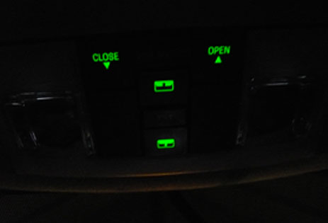
:happy feet: SOLVED :happy feet: Here is the final solution! ------------------ Tie into blue wire w/red striped wire connector for the mirror up in the headliner - this is your power source Tie into whatever ground you desire (metal connection in roof, black #14 pin wire, there is a metal bolt right there in roof) - this is your ground Power source wire goes into pin hole #2 Ground wire goes into pin hole #1 You decide your own connections. ------------------ see my previous posts about location of said 2 critical pin holes and photos. Thanks for the help and tip offs.... it allowed me to trial and error and piece it all together! Enjoy as it is a great, simple mod. knowing what I have here now, this is maybe a 15-20 minute mod well worth the effort. When you supply power to car, viola... you can now see the lights at night
-
MOON ROOF CONTROL LIGHTING
Lex Talionis replied to sanche's topic in Audio, Backup, Navigation & SYNC
I would, for the most part, tend to agree. I can think of ways around soldering, but that is not any concern to me. connections are easy, what to connect to is the question not totally, so I was just confirming well, a push fit splice connector makes that hella easy & you can draw from a confirmed ground off wire to pin 14 yes, that was what I was confirming that it was still, in the end, a bunch of trial and error and no one can definitively just say or recall or confirm yet: "ground pin 1 and run power to pin 2". so we are no further along just yet. so, I will do some of that continued trial and error now I did not have time for this weekend. -
Upgrade cd changer to NAV with Sync?
Lex Talionis replied to sleighbor's topic in Audio, Backup, Navigation & SYNC
yes it is. if you search the posts here, you can find plenty of threads with photos, directions, model numbers, reviews, etc. an after market option would even allow for other neat options like backup camera, additional video/audio ports, etc. but many of those threads are long and detailed so easier to read what has been done already. -
MOON ROOF CONTROL LIGHTING
Lex Talionis replied to sanche's topic in Audio, Backup, Navigation & SYNC
BUT the MKX is wired for it from the factory. The Edge is not, there in lies the rub... wiring -
MOON ROOF CONTROL LIGHTING
Lex Talionis replied to sanche's topic in Audio, Backup, Navigation & SYNC
agreed. plus I want to do it myself. plus I am not willing to pay. plus it is totally DIY. once we get passed this korny holdup with the pin determination, it will be and seem like a piece of cake to do this mod. there is a bit of maybe, possibly, perhaps right now, but this will break wide open soon and then, it will have been worth the few hours to hassle it out as the next guy will do in 20 minutes what I spent a few hours trying to do. there is certain fun in solving these projects (for me at least). -
2 weeks past and I go this, "havent heard anything from R+D department, but i"ll look into it..." so that does not bode well for an immediate release UPDATE 9.10.08: got this random email this week from them, "will be coming out soon,, getting closer."
-
MOON ROOF CONTROL LIGHTING
Lex Talionis replied to sanche's topic in Audio, Backup, Navigation & SYNC
Hey thanks... first, why did you order the MKX part? just for the look of it? It seems the Edge one would work, so not sure why got the MKX part? Yes, pin 14 is ground. Pin 1 is open, so you might be correct about it needing ground. But not sure where your applying power? I see where you are getting it (the mirror), but not applying it (to a pin)? Q: Could ground just be taken from the existing ground by tapping into & running a jumper from the black wire in the gray pigtail/molex of pin 14 and then attached to pin 1. Then, power is taken by tapping into blue w/red striped wire on mirror but it is applied to what/where - that is what I am missing, is that what you have forgotten - are you implying you could run the ground to pin 1, and then just touch the mirror power jumper to the pins until you find which one lights the LEDs, obviously you would need headlights/power on to car as well or is the mirror power constant? -
MOON ROOF CONTROL LIGHTING
Lex Talionis replied to sanche's topic in Audio, Backup, Navigation & SYNC
that would be awesome. clearly, you know a bit more about voltage meters and using them than I do. that is where I am stalled out at. I really thought all the tricks I tried would have revealed it to me by now, but I believe correct usage of a voltage meter can put this all to rest. so, if you can, try to determine what pin(s) first, and where we can tap in to power. thanks. -
MOON ROOF CONTROL LIGHTING
Lex Talionis replied to sanche's topic in Audio, Backup, Navigation & SYNC
yeah, we kind of discussed this earlier, I am just not adept with a voltage meter. The control unit comes down super, duper easy and consists of the trim/map lights/sunglasses holder. then, when you unplug the white and gray pigtails, you can pull the whole unit out. maybe 5 seconds. if you wish, you can even remove the actual stand alone BAMR controls from the full unit in about 5 more seconds as it is just snap fit into the full unit - you will then have the stand alone controls and map lights as one separate unit and can run you tests as that piece is just snap fit into the trim/sunglass housing. if you wish, you could even go a step further and separate the actual stand alone BAMR controls into a further 2 pieces of top (switches) and bottom (motherboard). so, if you want to get involved, if you could figure out what pins ultimately would feed voltage to the LEDs, that would be great. It seems Jpark did that when he mentioned "pins #1 and #2".. but if someone adept with a voltage meter could confirm that it would be great. Then, once we confirm that, what the next step it? supplying power to both pins? -
Engine RPM jumps to 1,500 while sitting still
Lex Talionis replied to frankeplatt's topic in Mods & Tech
"a normal characteristic of vehicle" great, so will they stand by that & you when they/you get sued when your car lurches forward at a stop sign and hits a pedestrian because this car revs up and bolts & you can't hold it? "when setting at a stop light/sign, the engine's RPM speed will jump 1,000 RPMs to around 1,500" + "so severe that I had to hold the brake o the point that I experienced a POP" / car giving you the wrench symbol = very scary situation -
MOON ROOF CONTROL LIGHTING
Lex Talionis replied to sanche's topic in Audio, Backup, Navigation & SYNC
yeah, other heads involved would be good. my head is starting to spin with the fast and furious work I have been doing on this to try to solve it. I love a good challenge and the thrill of the hunt, but I feel like I am missing something obvious here. when I touched the grounded test light to the pigtail lead holes from the roof liner, that is when the different events triggered (open, close, shade, etc) and allowed me to narrow down what pigtail lead, and thus what pin on the MB, did what. MB was on the floor at that time. Is your logic then that maybe the golden pin(s) would need ground to possible activate the LED lights based on what I found? If so, you would have to hook the pigtail into the MB and then on the open lead holes, slide in a wire or something (since it is such a small opening) to make connect through the open hole with the pin and see if ground also activated the LEDs. but if that were true, why would Jpark mention a wire needing to go to a delayed power source? remember, it seem pin and pigtail 14 supply ground to the MB when plugged in. I would say it is time you get involved with your Edge also.. I agree we are close. -
MOON ROOF CONTROL LIGHTING
Lex Talionis replied to sanche's topic in Audio, Backup, Navigation & SYNC
yep, I at least knew the - and + color correspondance , just not so much how to read and set it up. either way, I would think, with all I have tracked down and photoed above, we should be able to solve this without going that route and taking that unit apart to get readings, no? with those photos, and the detail on the pins I just provided, it seems we should be able to determine what pin will activate those darn LEDs? at this stage, it seems I should be able have the gray pigtail plug plugged into the motherboard harness (so the board has ground applied to the pins), slide through the open lead holes a power wire to one of the open pins and touch the pin and see the LED lights light up through the buttons face like on the steering wheel... no? it seems all about just providing power to one - I assume just 1 - of the pins to determine which pin is the one to trigger the lights? I will worry about tracking the correct power source to the pin later, but figuring the pin first is key. Not sure why Jpark said pin #1 AND #2 as I would think 1 pin would power all 4 LED lights at 1 time? I am also assuming the #1 and #2 referenced 'pins' are in fact one of those not used on the motherboard side that the gray pigtail mates to. note: I blew a fuse, I think #25 10 amp, trying to apply power - jumped from a local power source in the same area - to the open pins. so not sure if to much power, or the ground to the pins via #14 is not the only ground we need and we need another along with power... I assumed the ground, black #14 was grounding the full unit, it seems not though with the blown fuse result. -
MOON ROOF CONTROL LIGHTING
Lex Talionis replied to sanche's topic in Audio, Backup, Navigation & SYNC
NEW INFO I have confirmed (by using a test light and grounding it to frame and touching it to all used leads with key turned to on) the following leads functions: 5 - close sun shade 6 - open sun shade 8 - close BAMR 10 - open vent feature BAMR 11 - open BAMR 14 - no action, so I assume it is the ground (black wire) with key into on position, and grounding the test light on frame of car, none of these light the test light to show power, they just close the circuit and made the above functions trigger. I am thinking the power is actually coming in via the white pigtail plug as the overhead map lights stay on even when I remove the gray pigtail - showing power source. so the gray pigtail is providing control to the motherboard, but it seems the white pigtail is giving power to it. when I ground the test light and touch these 3 metal leads behind the overhead map lights, the test light powers up on all 3 leads (1 handles power always when key in, 1 powers up only when door open triggers it, one provides power only when push map light button). Now this being said, I will see about posting a better pict of what Jpark had of motherboard BUT to do that you really have to break that whole unit down... it is numerous pieces stacked together.... which is kind of a PITA I can tell. So, I want to try to solve it prior to getting to that level. I have a voltmeter, but honestly I need some help setting it up to conduct tests as that has always been a mystical unit to me. For example, the red lead and black leads plug into what ports on the meter? then, what do I set the meter selector to? then, once I get it setup, how do I test continuity between solder pin and LEDs? touch it (black ground) to the solder area and touch the metal area of the LED with red power lead? and then, what readout am I looking for? again, this would all require breakdown of that whole unit and I would love to solve this by using my test light data above if possible as I think it we have access to all we need here without taking that unit apart down to the motherboard. -
2008 Edge limited, chimes 3x at closing only. nothing at opening.
-
MOON ROOF CONTROL LIGHTING
Lex Talionis replied to sanche's topic in Audio, Backup, Navigation & SYNC
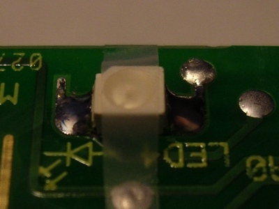
okay.. given my new info above, we posted at same time.. what do you think now? In looking at the motherboard we currently have wires coming into pins 5,6,8,10,11,14 If so, now what process might we follow to determine which pin(s) will make this happen? Jpark references pins #1 and 2. It seems to me you should be able to run a power wire up to the gray pigtail and into open lead/holes #1 and #2, touch the pin, and see if it fires up those lights.. no? ground is in place, so it seems just adding power to those pins 1 at a time until it lights up would tell us what pin and not harm this motherboard. once you figure that, you could then tie it into the correct "accessory delay feed" power wire (which still needs to be determined yet). would we agree on this or is there a better method? what would solve all of this so easy would be if someone reading this with a Lincoln - like MKX2007 :) would pop down this control panel - very easy, just pull down the edge closest to your head - and snap a photo like my last one above that shows what color wires come into what port on the back of that pigtail. then we could clearly see what wire we are missing AND what color it is AND what lead/port it goes into on that pigtail... (that tape on the led is not my photo, it is one I found and posted for reference) -
MOON ROOF CONTROL LIGHTING
Lex Talionis replied to sanche's topic in Audio, Backup, Navigation & SYNC
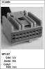
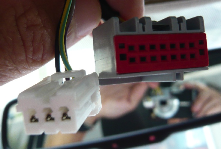
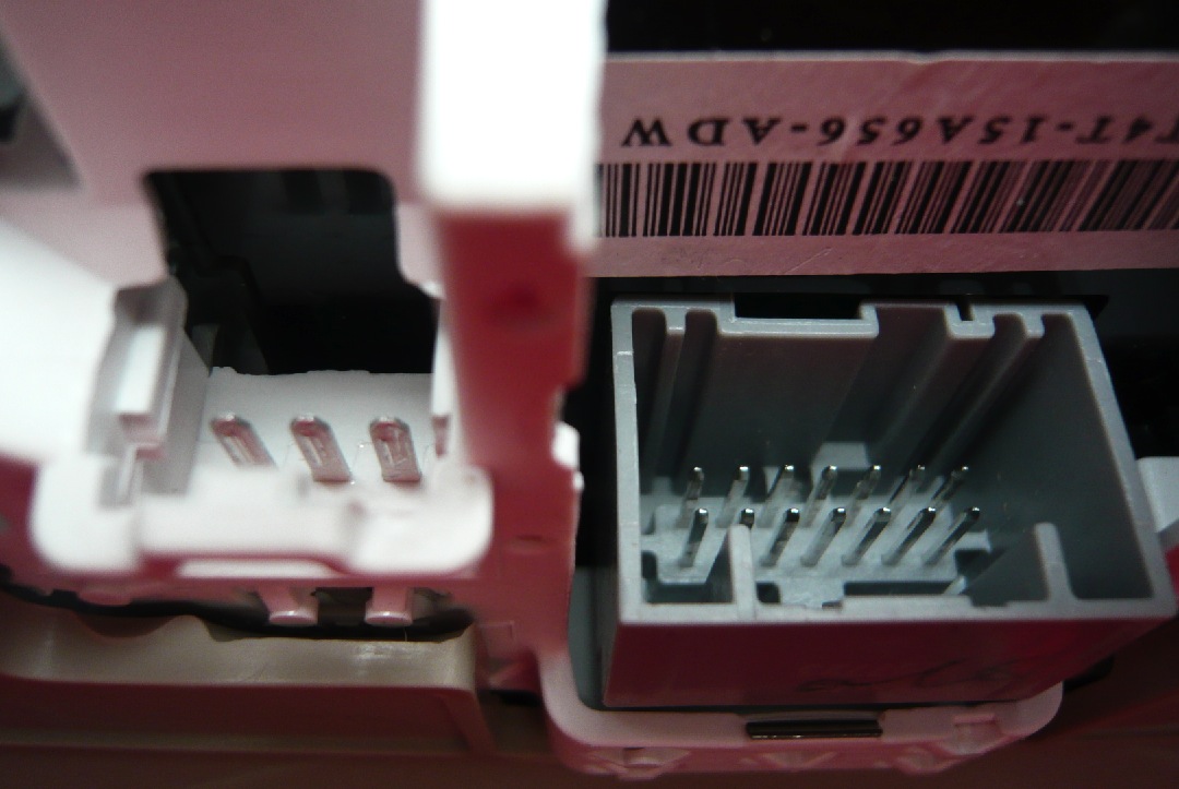
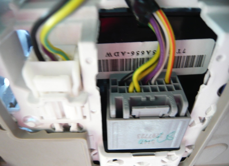
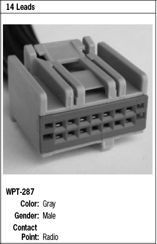
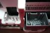
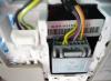
So, it dawned on me last night what this whole "pin" reference was and I am one step closer to solving this. :shades: On the flip side of the mother board are 2 pinned harnesses ports that the 2 pigtails from the headliner plug into. Notice the 2 pigtails are white and gray. Notice the gray port on the motherboard has 14 "pins" while the white port has 3 larger pins. The gray one seems to power the BAMR roof controls while the white one seems to supply power to the overhead map lights. I believe these are the 'pins' Jpark reference, they were never seen in his photo as they are on the opposite side. Now, look at just the gray pigtail - the key one in solving this I believe - coming from the headliner - as the pictures show, there are 18 lead/pin holes available in total, not 14. BUT also notice that we only use 6 of them (as seen by looking at the wires in the bundle that come into the backside of the gray pigtail). So, when you plug this pigtail in, it is contacting just 6 of the 14 open pins on the motherboard side. So, this tells me that in the Lincoln, there is/are another wire(s) coming into that gray pigtail in that wire bundle and in the end, making more than 6 pin connections. This lines up with Jparks reference to just needing another '3 feet of wire' as the ground is there already for us. SO.. the million dollar questions are (1) what lead/pin hole would you run a wire into (notice there are 8 to select from that would line up with pins), which one is the golden pin and (2) what color existing wire would you tap into the existing wire bundle to get the correct power if you knew what lead/pin hole to tap into. Jpark mentions "accessory delay feed" - if so, what color is that currently?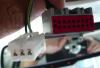
-
MOON ROOF CONTROL LIGHTING
Lex Talionis replied to sanche's topic in Audio, Backup, Navigation & SYNC
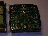
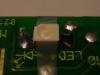
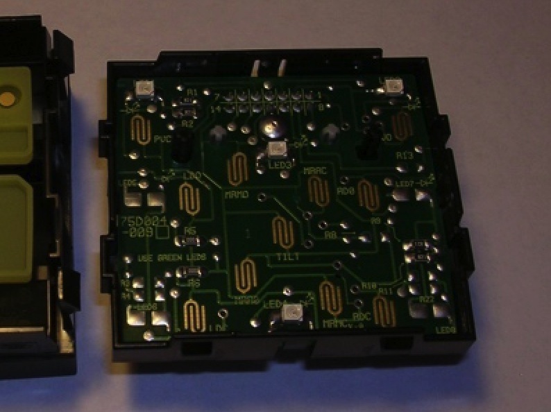
I believe what you see as 'pins' are, in fact, actually slices in the plastic housing that are for the clips on the opposite piece to snap home. I have attached a blown up pixelated image of that board, you can see only circuits at the top of that board. no 'pins' that I see. The image below that I found also and it seems to show the motherboard taken out of the plastic housing - maybe giving access to actual pins on the other side? I would tend to agree if it is that simple and allows to plug-n-play activation by hooking into the existing harness that is in the head liner and not have to run a wire. I would buy it as it would be clean and take advantage of prewired ground and power. IF that is what it does (see the pig tail image I found below). I might actually go by the dealer and have them pull up this section of Edge parts on their computer and then pull the same parts up for the Lincoln and see if it shows an additional pigtail or inline adaptor versus the Edge model parts - or at least, show this section of parts and what a discernible difference is.