
Haz
Edge Member-
Posts
1,350 -
Joined
-
Last visited
-
Days Won
357
Content Type
Profiles
Forums
Gallery
Everything posted by Haz
-
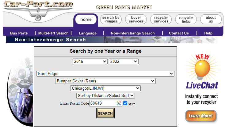
If the OEM Service parts supply has been exhausted, then you might try tapping into the Salvage Yard used parts market. Understandably, the Car-Parts.com used parts search engine lacks a specific identifier for rear bumper air deflector, but a decent starting point may be searching for rear bumper covers and then communicating with the Salvage Yard using images from the Forum discussion thread to ensure the vehicle might have been equipped with an air deflector that your looking for. A non-Trailer Tow deflector should also work for you with a little trimming, per Forum member @chipdog4's advice in this post. 2015 to 2022 model year Edges should be a good target, and the search I ran for the Chicago-metro area yielded many rear bumper covers, though you could select a wider area... Good luck!
-
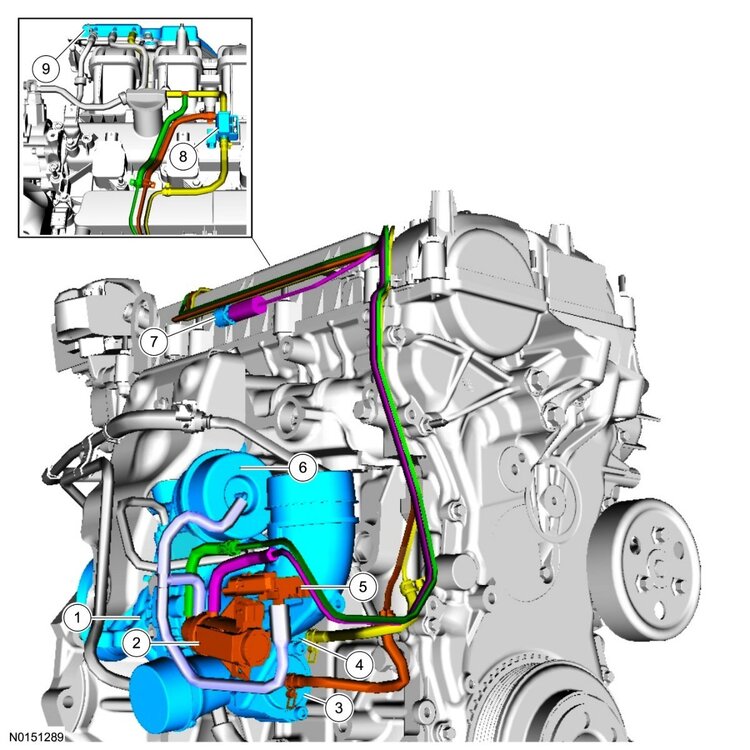
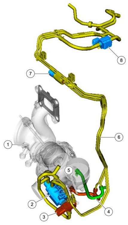
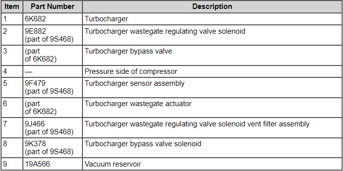
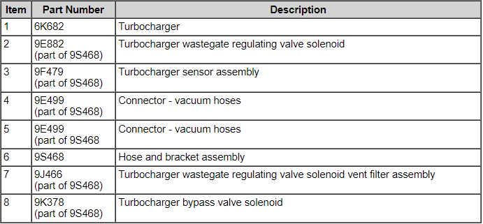
Welcome to the Forum @59panman! Turbocharger-related component illustrations from the 2012 Edge Workshop Manual... From the Ford Powertrain Control/Emission Diagnosis Manual for 2012 Ford Gasoline Engines... Pinpoint Test HN, and other supporting sections from 2012 Edge Workshop Manual and 2012 Edge Wiring Resource are attached below as PDF documents... Good luck! Turbocharger - Description and Operation - 2012 Edge Workshop Manual.pdf Turbocharger System - Diagnostic Pinpoint Test HN - Ford PC-ED Manual for 2012 Gasoline Engines.pdf Turbocharger Wastegate Vacuum Sensor - Wiring Diagram.pdf WASTEGATE VACUUM SENSOR - Connector C1644 Pins-Circuits Details - 2.0L EcoBoost - 2012 Edge.pdf WASTEGATE VACUUM SENSOR - Connector C1644 Location - 2.0L EcoBoost - 2012 Edge.pdf Turbocharger Wastegate Regulating Valve Solenoid and Bypass Valve - Wiring Diagram - 2.0L EcoBoost - 2012 Edge.pdf TURBOCHARGER (TC) WASTEGATE REGULATING VALVE SOLENOID - Connector C1246 Pins-Circuits Details - 2,0L EcoBoost - 2012 Edge.pdf TURBOCHARGER (TC) WASTEGATE REGULATING VALVE SOLENOID - Connector C1246 Location - 2.0L EcoBoost - 2012 Edge.pdf TURBOCHARGER BYPASS VALVE (TCBY) - Connector C1650 Pins-Circuits Details - 2.0L EcoBoost - 2012 Edge.pdf TURBOCHARGER BYPASS VALVE (TCBY) - Connector C1650 Location - 2.0L EcoBoost - 2012 Edge.pdf
-
While technically, the linked TSBs have not been extended to the 2024 model year, given your Edge ST's probable in-warranty status -- and especially if the noise is cold-start repeatable -- it would be worthwhile to have it evaluated by your dealer, though they will likely want it sitting at the dealership overnight to perform a truly cold-start the following day. Good luck!
-
Just checking, since inoperative cooling fans could explain A/C performance difference between vehicle stopped at idle and vehicle being driven at speed. Good luck!
-
Does the electric cooling fan(s) immediately run after you begin operating the A/C system? Good luck!
-

2011 Edge Limited , no power to windows ,No blue wire supply power .
Haz replied to Ford2504x4's topic in 2013 Edge & MKX
From the 2011 Edge Workshop Manual and Wiring Resource, posted here and also attached below as PDF documents... Pinpoint Test L: The Delayed Accessory is Inoperative Normal Operation The accessory delay relay is located in the Body Control Module (BCM) . When the ignition is in the ON position, the BCM activates the accessory delay relay by grounding the relay coil. When the ignition is turned to the OFF position, the BCM continues to ground the accessory delay relay coil for approximately 10 minutes, or until a front door is opened. When the accessory delay relay is active, it supplies voltage to the power window system. DTC B131A:12 (Delayed Accessory Power: Circuit Short To Battery) — sets when the BCM senses a short to voltage on the accessory delay relay control circuit. DTC B131A:14 (Delayed Accessory Power: Circuit Short To Ground or Open) — sets when the BCM senses an open or short to ground on the accessory delay relay control circuit. This pinpoint test is intended to diagnose the following: Door ajar switches Accessory delay relay BCM PINPOINT TEST L : THE DELAYED ACCESSORY IS INOPERATIVE NOTICE: Use the correct probe adapter(s) from the Flex Probe Kit when making measurements. Failure to use the correct probe adapter(s) may damage the connector. L1 CHECK FOR CORRECT OPERATION OF THE DOOR AJAR SWITCHES Open and close the front doors. Verify the interior lights turn on when the doors are open, and off when the doors are closed. Do the interior lights operate normally? Yes GO to L2. No REFER to Section 417-02 to diagnose the interior lighting and door ajar switches. L2 CHECK THE ACCESSORY DELAY RELAY Carry out the accessory delay relay component test. Did the accessory delay relay pass the component test? Yes GO to L3. No INSTALL a new accessory delay relay. CLEAR the DTCs. REPEAT the self-test. TEST the system for normal operation. L3 CHECK FOR CORRECT BCM OPERATION Disconnect all BCM connectors. Check for: corrosion. pushed-out pins. Connect all BCM connectors and make sure they seat correctly. Operate the system and verify the concern is still present. Is the concern still present? Yes INSTALL a new BCM . REFER to Section 419-10 for the removal and installation procedure. TEST the system for normal operation. No The system is operating correctly at this time. Concern may have been caused by a loose or corroded connector. CLEAR the DTCs. REPEAT the self-test. TEST the system for normal operation. Good luck! Power Window, Left Front - Wiring Diagram - 2011 Edge.pdf Window Motor Initialization - General Procedures - 2011 Edge Workshop Manual.pdf Master Window Adjust Switch - Component Testing Procedure - 2011 Edge.pdf Window Adjust Switch - Component Testing Procedure - 2011 Edge.pdf Body Control Module (BCM) - Illustration showing Accessory Delay Relay location - 2011 Edge.pdf Accessory Delay Relay, 5-Terminal - Component Testing Procedure - 2011 Edge.pdf Glass, Frames and Mechanisms - Diagnosis and Testing - 2011 Edge Workshop Manual.pdf -
Europe/United Kingdom 2022 Edge Rear Fog Lamps wiring diagrams, connector details and locations, attached below as PDF documents... Good luck! Rear Fog Lamps - Wiring Diagram #1 - 2022 Edge - United Kingdom.pdf Rear Fog Lamps - Wiring Diagram #2 - 2022 Edge - United Kingdom.pdf Rear Fog Lamps - Wiring Diagram #3 - 2022 Edge - United Kingdom.pdf Rear Fog Lamp, LH - Connector C436 Location, Rear View - 2022 Edge - United Kingdom.pdf Rear Fog Lamp, LH - Connector C436 Pins-Circuits Details - 2022 Edge - United Kingdom.pdf Rear Fog Lamp, RH - Connector C437 Location, Rear View - 2022 Edge - United Kingdom.pdf Rear Fog Lamp, RH - Connector C437 Pins-Circuits Details - 2022 Edge - United Kingdom.pdf Rear Fog Lamps - Inline Connector C438 Location, Inside View - 2022 Edge - United Kingdom.pdf Rear Fog Lamps - Inline Connector C438 Location, Rear View - 2022 Edge - United Kingdom.pdf
-
Welcome to the Forum, @bw228! Active Noise Control (ANC) microphones wiring diagram, connector details, locations, removal and installation info attached below as PDF documents... Good luck! Active Noise Control (ANC) Microphone - Removal and Installation - 2021 Edge Workshop Manual.pdf Active Noise Control (ANC) Microphones - Inline Connector C211 Pin-Circuit Details - 2021 Edge.pdf Active Noise Control (ANC) Microphones - Inline Connector C211 Location - 2021 Edge.pdf Active Noise Control (ANC) Microphones - Inline Connector C913, Pin-Circuit Details - 2021 Edge.pdf Active Noise Control (ANC) Microphones - Inline Connector C900, Pin-Circuit Details - 2021 Edge.pdf Active Noise Control (ANC) Microphones - Inline Connector C913 Location - 2021 Edge.pdf Active Noise Control (ANC) Microphones - Inline Connector C900 Location - 2021 Edge.pdf Active Noise Control (ANC) Microphones - Wiring Diagram - 2021 Edge.pdf Active Noise Control (ANC) Microphone - Rear, Connector C9928 - 2021 Edge.pdf Active Noise Control (ANC) Microphone - Right Front, Connector C9927 - 2021 Edge.pdf Active Noise Control (ANC) Microphone - Left Front, Connector C9926 - 2021 Edge.pdf
-
From the 2024 Edge Workshop Manual... Auto-Start-Stop System The Auto-start-stop system helps reduce fuel consumption by automatically shutting off the vehicle’s engine while the vehicle is at a complete stop and restarting the engine when the brake pedal is released. The system can be disabled through the auto-start-stop control switch on the instrument panel centerstack. The Auto-start-stop system is automatically enabled whenever the ignition is turned on. The engine automatically restarts when: the brake pedal is released. the Auto-start-stop system is disabled through the auto-start-stop control switch on the instrument panel centerstack. the battery has a low state of charge. it is necessary to maintain interior comfort. the blower fan speed is increased or the climate control temperature is changed. an electrical accessory is turned on or plugged in. there is low brake vacuum. The Auto-start-stop system may not turn the engine off under these conditions: the HVAC system is in A/C, heat or defrost modes. the rear defroster is on. the battery has a low state of charge. the battery temperature is below 5°C (41°F) or above 60°C (140°F). the engine temperature is below 46°C (115°F). the engine temperature is below 60°C (140°F) and the HVAC system is in heat mode. the gear selector is not in Drive or Sport Mode. the steering wheel is turned rapidly or is at a sharp angle. vehicle speed of greater than 4 km/h (2.5 mph) for more than 2 seconds has not occurred. the vehicle is on a steep road grade. elevation is approximately above 3,048 meters (10,000 feet). And... Direct Current/Direct Current (DC/DC) Converter Control Module - System Operation and Component Description System Diagram System Operation Network Message Chart Broadcast Message Originating Module Message Purpose Engine status PCM Used to indicate the type of cranking event occurring. If the signal is state 2, Engine Auto Stopped, then the next commanded crank is to be supported. If the signal is state 0, Engine Off, the next crank will be a key crank and the Direct Current/Direct Current (DC/DC) converter control module will not support. The Direct Current/Direct Current (DC/DC) converter control module, also known as the Voltage Quality Module (VQM), is responsible for boosting battery voltage to specific components on vehicles equipped with the auto-start-stop system. When the ignition is turned on the Direct Current/Direct Current (DC/DC) converter control module initializes after receiving the Run/Start power feed from the BCM controlled run/start relay. While in stand-by mode the Direct Current/Direct Current (DC/DC) converter control module performs self-diagnostics and is not producing any boost output voltage. The Direct Current/Direct Current (DC/DC) converter control module is simply passing battery voltage straight through to downstream loads when it is in stand-by mode. The Direct Current/Direct Current (DC/DC) converter control module continuously communicates it's status to the PCM via High Speed Controller Area Network (HS1-CAN). If the Direct Current/Direct Current (DC/DC) converter control module is overloaded, overheated, or other faults are present the PCM disables the auto-start-stop system. If a fault is detected, the PCM may restart the engine if an auto-start-stop event is already in progress. During an auto-start-stop event the engine shuts down automatically after vehicle speed is zero. As the engine begins shutting down, there is an initial battery voltage drop due to the engine shutting off and the alternator no longer providing output current. Once the engine is no longer spinning, the electrical system is fully supported by the vehicle battery. The electrical load present in the engine off phase of the auto-start-stop event causes a gradual decline in battery voltage. This gradual decline of battery voltage is the second voltage transition. The third voltage transition occurs during the engine restart. The system voltage drops, followed by the system voltage increasing to the regulation voltage point determined by the alternator output. Prior to the engine restart, the PCM sends a low-side drive command to the the low voltage Direct Current/Direct Current (DC/DC) converter. The low voltage Direct Current/Direct Current (DC/DC) converter is switched into Boost mode to stabilize/boost its output until the engine has started and system voltage regulation is established by the alternator. The converter provides the stabilized or boost output voltage until one of the following occurs: Boost time exceeds 5 seconds System input voltage exceeds targeted output The Direct Current/Direct Current (DC/DC) converter control module has full bypass or stand-by mode functionality within an input of 6V-16V. The Direct Current/Direct Current (DC/DC) converter control module must be able to provide the boosted voltage with a minimum 6V power net input voltage. If the supply voltage goes outside the voltage range, the Direct Current/Direct Current (DC/DC) converter control module recovers without user intervention when the supply voltage returns to the normal operating range. The Direct Current/Direct Current (DC/DC) converter control module determines the stabilized output voltage to be targeted by continuously measuring the Direct Current/Direct Current (DC/DC) converter control module input voltage. Prior to the restart event, the Direct Current/Direct Current (DC/DC) converter control module receives the RE-CRANK signal and sets the boosted output voltage target to be equivalent to the measured input voltage. This makes sure the output voltage to the supported loads does not change. Malfunction of the system does not lead to non-function of other vehicle systems. The system enters bypass mode if: a thermal overload condition exists. there is a Direct Current/Direct Current (DC/DC) converter control module failure. the output voltage is more than 1V below input voltage and voltage boost is not available. The Direct Current/Direct Current (DC/DC) converter control module self-protects against overheating and self-recovers without user interaction after an overheating event and is internally protected from short-circuits. Component Description The Direct Current/Direct Current (DC/DC) converter control module is connected in series between the high current fuse box and a select number of non-safety electrical loads. The majority of the loads are fused through the BCM and remaining loads are not fused and are switched on by a smart transistor located internal to the Direct Current/Direct Current (DC/DC) converter control module. The smart transistor acts as a fuse and shuts off power in the event of a short to ground. The Direct Current/Direct Current (DC/DC) converter control module has a dedicated body ground and incorporates a hardwired signal circuit from the PCM which notifies the Direct Current/Direct Current (DC/DC) converter control module prior to the engine cranking during an auto-start event. Good luck!
-
Welcome to the Forum, @Joe7777777! The Interior Rear View Mirror section of the 2014 Edge Workshop Manual, attached below as a PDF document, shows four different styles of mirrors. The document illustrates each style of mirror mount and it may assist you toward reattaching your 2014 Edge's interior rear view mirror. In some cases, special tools may be useful. Good luck! Interior Rear View Mirror - Removal and Installation - 2014 Edge Workshop Manual.pdf
-
@markfm: Thanks for the heads-up! I surveyed over a dozen 2024 Nautilus offered as used vehicles at Lincoln/Ford and dealerships of other brands. About half of the vehicles showed software updates on either June 10th, June 11th, or June 12th, involving these five modules -- Audio Front Control Module (ACM), Gateway Module A (GWM), Image Processing Module A (IPMA), Telematics Control Unit (TCU) and Vehicle Dynamics Control Module (VDM). No involvement of Ford Diagnostic & Repair System (FDRS) is shown, so this update grouping were surely delivered Over The Air (OTA). Good luck!
-

Ford Pass: vehicle in battery saver mode
Haz replied to sc00by's topic in Alarms, Keyless Entry, Locks & Remote Start
Welcome to the Forum, @sc00by! The FordPass app's reaction to your 2020 Edge ST's likely borderline Battery State of Charge (SOC) and/or Battery Voltage condition is the result of Battery Load Shed strategy, described in the Workshop Manual section attached below as a PDF document... Good luck! Battery Load Shed - Description and Operation - 2020 Edge Workshop Manual.pdf -
@Davidoo: Ford has narrowed access to Connected Vehicle data to protect vehicle owner privacy, so I'm no longer able to access any cross-reference of numerical software version to Ford Power-Up designation. Your dealership Service Writer should be able to view the Connected Vehicle data that includes an Over The Air (OTA) Dashboard, which shows past OTA vehicle updates with a pop-up description of their Power-Up designations. Good luck!
-
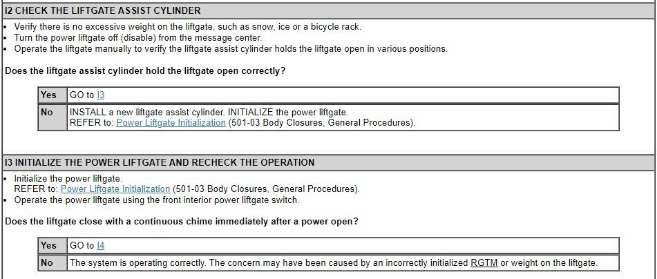
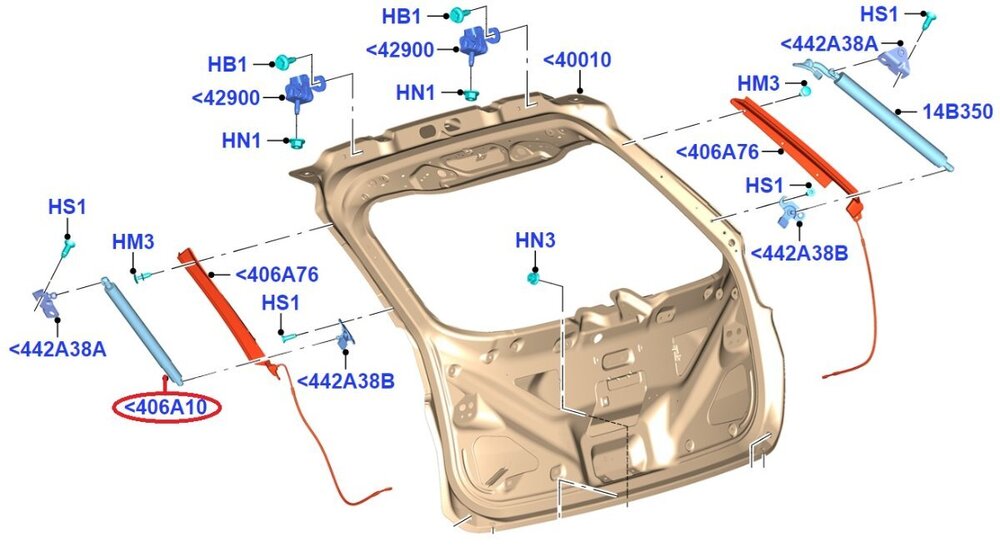
@ksquared: Good to hear your Edge has been reasonably trouble-free since you purchased it in late 2019. Because you describe the liftgate raising in a more pronounced way on its left side, where the power motor assembly is located, I'm wondering if you've ever replaced the gas-filled lift assist strut that is located on the right side of the liftgate? The following, from the 2016 Edge Workshop Manual, is an edited version of Power Liftgate diagnostic Pinpoint Test "I", aimed toward evaluating the gas-filled lift assist strut... Possible Causes Excessive weight on the liftgate, such as snow, ice or a bicycle rack Liftgate assist cylinder Power liftgate initialization If results indicate Liftgate cylinder replacement is needed, help from an assistant to support the weight of the Liftgate while the retaining clips are released, the Liftgate cylinder is removed, and the Liftgate is manually lowered in a safe and controlled way... Web searching the Ford part number will likely many online sellers and lower pricing. If the Liftgate cylinder supports the Liftgate at all positions, then you may want to perform the Power Liftgate Initialization procedure from the Edge Workshop Manual... Power Liftgate Initialization Disconnect the battery or remove the RGTM fuse(s). NOTE: Remove the battery power from the RGTM for 20 seconds before entering initialization mode. Wait 20 seconds and reconnect the battery or reinstall the RGTM fuse(s). If the liftgate is not already in the fully closed position, manually close and fully latch the power liftgate. Using a diagnostic scan tool, clear all fault codes for the RGTM . NOTE: If equipped, make sure the power liftgate system is turned ON in the message center before performing this step. NOTE: If the power liftgate does not open during this step, refer to the Symptom Chart to diagnose the inoperative power liftgate. Power open the liftgate by using a programmed RKE transmitter or the front control switch. Once the liftgate is fully open, power close the liftgate by using a programmed RKE transmitter or the front power liftgate control switch. Carry out the RGTM self-test. The wiring diagram shows the Rear Gate Trunk Module (RGTM) power is protected by Fuse 10 (5-amp)... If neither of these courses of action yield improvement, you may want to get your Edge's modules scanned for Diagnostic Trouble Codes (DTCs), perhaps at a National Brand auto parts store or your favorite neighborhood parts store, then please report back and we'll consider additional diagnostic procedures. Several of the above references are attached below as PDF documents... Good luck! Body Control Module (BCM) - Location Illustration - 2016 Edge.pdf Rear Gate Trunk Module (RGTM) - Power Distribution Wiring Diagram - 2016 Edge.pdf Body Control Module (BCM) - Fuse-Circuit(s) Listing - 2016 Edge.pdf Body Control Module (BCM) - Illustration Showing Fuse & Connector Locations - 2016 Edge.pdf Power Liftgate Initialization - General Procedures - 2016 Edge Workshop Manual.pdf
- 1 reply
-
- 1
-

-

Installing cost-cut centre console cover
Haz replied to GTEyes's topic in Interior, A.C., Heat, Interior Trim
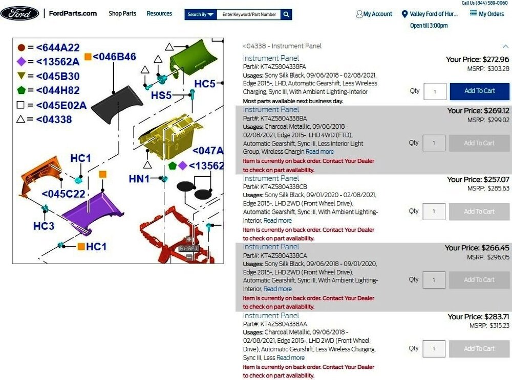
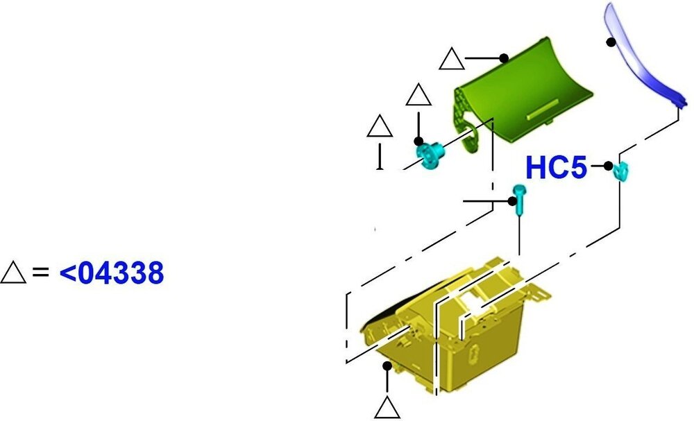
FordParts.com lists varied part numbers for the bin-with-hinged-door assembly, based upon Door Color Finish/2020 Vehicle Build Date/Additional Equipment... Link to the FordParts.com components illustration above, which is zoomable and scrollable in your web browser, shown below edited as isolated view, for clarity... Good luck! -

Installing cost-cut centre console cover
Haz replied to GTEyes's topic in Interior, A.C., Heat, Interior Trim
Ford Edge owners re-contenting Ford's de-contenting of their vehicles -- Fabulous! Though, with apologies to Poe's Raven, quoth-ing Ford, "Warrantable? Nevermore." Now, onto the documents... Differences between disassembly steps in the below-attached sections of the 2020 & 2021 Edge Workshop Manuals may provide you the insights you're seeking. Please note: Some numbered action steps, which apply to their immediately-following illustrations, may appear on the page before their rightful illustration. We especially look forward to your photos. Good luck! Front Controls Interface Module (FCIM) - Removal and Installation - 2020 Edge Workshop Manual.pdf Floor Console - Removal and Installation - 2021 Edge Workshop Manual.pdf -
Additional... Good luck! Powertrain Control Module (PCM) - Removal and Installation - 2008 Edge Workshop Manual.pdf 6F TRANSMISSION - Connector C168 Location - 2008 Edge.pdf 6F TRANSMISSION Controls - Wiring Diagram - 2008 Edge.pdf 6F TRANSMISSION - Connector C168 Pins-Circuits Details - 2008 Edge.pdf Solenoid Body-to-Output Shaft Speed (OSS) Sensor Internal Circuit Diagram - 6F - 2008 Edge.pdf Solenoid Body-to-Turbine Shaft Speed (TSS) Sensor Internal Circuit Diagram - 6F - 2008 Edge.pdf
-
From the 2008 Edge Workshop Manual... Relevant 2008 Edge Workshop Manual and Wiring Resource sections are attached below and in an immediately following post as PDF documents... POWERTRAIN CONTROL MODULE (PCM) - Connector C175T Location - 2008 Edge.pdf POWERTRAIN CONTROL MODULE (PCM) - Connector C175T Pins-Circuits Details - 2008 Edge.pdf Main Control Valve Body - 6F50 - In-Vehicle Removal and Installation - 2008 Edge Workshop Manual.pdf Output Shaft Speed (OSS) Sensor - 6F50 - In-Vehicle Removal and Installation - 2008 Edge Workshop Manual.pdf Turbine Shaft Speed (TSS) Sensor - 6F50 - In-Vehicle Removal and Installation - 2008 Edge Workshop Manual.pdf Automatic Transmission 6F50 - Diagnostic Pinpoint Test C - TSS And OSS Sensors - 2008 Edge Workshop Manual.pdf
-
TECHNICAL SERVICE BULLETIN SYNC 3 - Various SYNC Symptoms 24-2182 05 June 2024 This bulletin supersedes 23-2307. Reason for update: Service Procedure and vehicle model years affected. Model: Ford 2021-2024 Bronco Sport 2020-2022 EcoSport 2019-2020 Edge 2020-2022 Escape 2020-2021 Expedition 2020-2024 Explorer 2019-2020 F-150 2019-2020 Fusion 2022-2024 Maverick 2019-2023 Mustang 2019-2023 Ranger 2020-2022 F-Super Duty 2020-2024 Transit 2019-2021 Transit Connect/Tourneo Connect Lincoln 2020-2024 Aviator 2019-2020 Continental 2020-2022 Corsair 2019-2020 MKZ 2019-2020 Nautilus 2020-2021 Navigator Issue: Some 2019-2020 Edge/F-150/Fusion/Continental/MKZ/Nautilus, 2019-2021 Transit Connect, 2019-2023 Mustang, 2019-2023 Ranger, 2020-2021 Expedition/Navigator, 2020-2022 Escape/Corsair/Super Duty/EcoSport, 2020-2024 Explorer/Aviator/Transit, 2021-2024 Bronco Sport, 2022-2024 Maverick vehicles with SYNC 3 may experience various SYNC performance related concerns including but not limited to: • Programming Failed via USB • Repeat FAIL - 8033 errors • Repeat "MEM_ERR", "PKG_ERR", "LIST_ERR", "SIGN_ERR" or "INST_ERR" errors • Repeat "Check Valid App Fail", "Fails to download to USB", "Configuration Failed" followed by inoperative display (2016 vehicles only) • Loss of audible voice prompts • Slow/lagging system response • Loss of Bluetooth pairing • Loss of navigation destinations • Slow/lag operation • Sirius audio not functioning properly after a key cycle with active subscription • Presets not responding or indicating properly • Intermittent audio echo/robotic voice heard during a Bluetooth phone call • Wi-Fi connection message pop-up every key cycle • Frozen unresponsive touchscreen • Solid blue screen when moving forward at speeds above 16 km/h (10 mph) (2019 vehicles only) • Rear parking aid camera remains on the screen at speeds below 16 km/h (10 mph) (2019 vehicles only) • Inoperative infotainment applications • Poor/no AppLink function • Apple CarPlay not launching on connection or a black screen when connected • Voice prompts that skip or have short pauses while directions are being provided • Sirius Travel Link™ not working properly with active subscription • Remote start not able to be scheduled from FordPass or Lincoln Way (2020 vehicles only) • System states In Michigan when trying to select a Point Of Interest (POI) on the navigation system • System scrolls through FM presets on screen when listening to Bluetooth or when on Android Auto/CarPlay • Climate control features missing after previous update • Temperature not displayed in pop up screen when increasing or decreasing temperature (2020-2021 Aviator/Navigator only) • Center display screen flicker (rear camera works properly) (2020-2022 Explorer/Aviator and 2020-2021 Navigator) This may be due to the SYNC Software. To correct the condition, follow the Service Procedure to update the accesory protocol interface module (APIM) software. Action: Follow the Service Procedure steps to correct the condition on vehicles that meet all of the following criteria: • One of the following vehicle lines: - 2019-2020 Edge/F-150/Fusion/Continental/MKZ/Nautilus - 2019-2021 Transit Connect - 2019-2023 Mustang - 2019-2023 Ranger - 2020-2021 Expedition/Navigator - 2020-2022 Escape/Corsair/Super Duty/EcoSport - 2020-2024 Explorer/Aviator/Transit - 2021-2024 Bronco Sport - 2022-2024 Maverick • Equipped with SYNC 3 • At least one of the following infotainment concerns: - Programming Failed via USB - Repeat FAIL - 8033 errors - Repeat "MEM_ERR", "PKG_ERR", "LIST_ERR", "SIGN_ERR" or "INST_ERR" errors - Repeat "Check Valid App Fail", "Fails to download to USB", "Configuration Failed" followed by inoperative display (2016 vehicles only) - Loss of audible voice prompts - Slow/lagging system response - Loss of Bluetooth pairing - Loss of navigation destinations - Slow/lag operation - Sirius audio not functioning properly after a key cycle with active subscription - Presets not responding or indicating properly - Intermittent audio echo/robotic voice heard during a Bluetooth phone call - Wi-Fi connection message pop-up every key cycle - Frozen unresponsive touchscreen - Solid blue screen when moving forward at speeds above 16 km/h (10 mph) (2019 vehicles only) - Rear parking aid camera remains on the screen at speeds below 16 km/h (10 mph) (2019 vehicles only) - Inoperative infotainment applications - Poor/no AppLink function - Apple CarPlay not launching on connection or a black screen when connected - Voice prompts that skip or have short pauses while directions are being provided - Sirius Travel Link™ not working properly with active subscription - Remote start not able to be scheduled from FordPass or Lincoln Way (2020 vehicles only) - System states In Michigan when trying to select a point of interest (POI) on the navigation system - System scrolls through FM presets on screen when listening to Bluetooth or when on Android Auto/CarPlay - Climate control features missing after previous update - Temperature not displayed in pop up screen when increasing or decreasing temperature (2020-2021 Aviator/Navigator only) - Center display screen flicker (2020-2022 Explorer/Aviator and 2020-2021 Navigator) Special Tool(s) SYNC 3 Universal Thumb Drive Warranty Status: Eligible under provisions of New Vehicle Limited Warranty (NVLW)/Service Part Warranty (SPW)/Service Part New Vehicle (SPNV)/Extended Service Plan (ESP) coverage. Limits/policies/prior approvals are not altered by a TSB. NVLW/SPW/SPNV/ESP coverage limits are determined by the identified causal part and verified using the OASIS part coverage tool. Labor Times Description Operation No. Time Reprogram The APIM Using The SYNC 3 Universal Thumb Drive (Do Not Use With Any Other Labor Operations) 242182A 0.3 Hrs. Repair/Claim Coding Causal Part: 14G371 Condition Code: 04 Service Instruction NOTE: For vehicles that are not currently at the dealership, the customer can also update their vehicle's SYNC 3 software via Wi-Fi or follow the instructions on www.owner.ford.com or www.owner.lincoln.com to update the SYNC 3 software. 1. Verify that the SYNC 3 universal thumb drive is titled SG3v202403 or later (later software levels will have a higher numerical value). Is the SYNC 3 universal thumb drive title SG3v202403 or later? (1). Yes - proceed to Step 2. (2). No - download the latest version of the SYNC 3 Universal USB Updater Application (1.0.3.1) under the Service Tips section of PTS using at least a 64GB USB 3.2 GEN 2 flash drive or higher. The USB drive must be formatted to exFAT. Review the instructions and use Scan for Updates and Update USB. Proceed to Step 2. • If needed, this is a one-time upload to the thumb drive. Instructions can be found on PTS under Service Tips. Downloading the files to laptop and updating the thumb drive could take up to 2 1/2 hours depending on internet speed. Once the thumb drive is updated, it can be used repeatedly to update all vehicles in this article. The thumb drive must be synced with the Updater Application every 30 days in order to retain usage permissions. 2. Disconnect all customer connected USB items from all media hub locations in the vehicle. 3. Start the vehicle. 4. Insert the SYNC 3 universal thumb drive into the USB port on the media hub. 5. The module automatically updates with no user input required. (1). Modules already at the latest software level indicate this after approximately 30 seconds. (2). Module programming for a non-updated module does not need to be monitored and can take approximately 20-30 minutes. (3). Once the reprograming has completed, the screen displays a message indicating the module is up to date. 6. Remove the SYNC 3 universal thumb drive when complete. The screen returns to the SYNC 3 home screen. Reconnect any of the customer USB items. No vehicle or system restarts are required. PDF download link> TSB 24-2182 - SYNC 3 - Various SYNC Symptoms - 06-05-2024.pdf
-
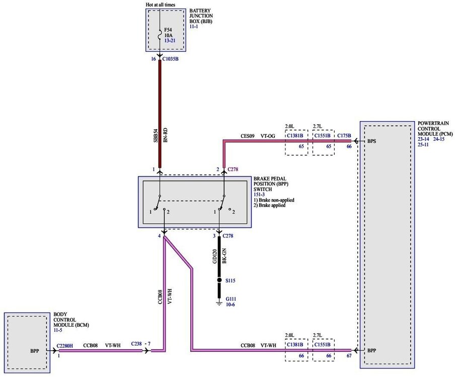
Boy, what a dope I am -- this is what happens when I substitute personal experience for Wiring and Workshop Manual documents. From the 2015 Edge Workshop Manual... The Brake Pedal Position (BPP) switch assembly contains the stoplamp switch and cruise control deactivator switch. When the brake pedal is applied, the cruise control deactivator switch, integrated in the BPP switch, opens and removes the ground signal from the PCM input circuit releasing the throttle, immediately deactivating the cruise control system. From the 2015 Edge Wiring resource... Brake Pedal Position Switch - Wiring Diagram - 2015 Edge Battery Junction Box (BJB) - Brake Pedal Position (BPP) Fuse 54 Red-Circled In Illustration - 2015 Edge Removing Fuse 54 from the BJB eliminates the Hot At All Times power from the BPP switch, and should extinguish the currently always-on stop lamps. De-energizing the BPP should also eliminate the vehicle's pushbutton Start function, since the PCM is no longer receiving any Stoplamp switch input. The question is: Does removing Fuse 54 restore the Edge pushbutton's ability to cycle to Accessory and Ignition On, while eliminating its Start function? Additionally, if the Stoplamp Switch component of the BPP has been stuck in always-on position, some of the following DTCs should be present in the PCM... If removing Fuse 54 restores the pushbutton Accessory On-to-Ignition On transition, try powering up your connected scanner with the Edge in Engine Off Ignition On state, and when it's fully operational, scan for DTCs. Make note of what -- if any -- DTCs are present, and then clear them. If Accessory On-to-Ignition On pushbutton functionality does not return, put Fuse 54 back in the BJB, start up your Edge's engine, turn off all accessory functions, then power up your scanner and once it's fully operational, scan for DTCs. Make note of what -- if any -- DTCs are present, and then clear them. If no DTCs are present, use you scanner to perform the following diagnostic test step to assess operation of the BPP functions... Several references are attached below as PDF documents... We look forward to feedback, and, I invite comments if I have -- once again -- overlooked something glaringly obvious. Good luck! Brake Pedal Position Switch - Wiring Diagram - 2015 Edge.pdf Brake Pedal Position Switch - Connector C278 Pins-Circuits Detail - 2015 Edge.pdf Stoplamp Switch - Removal and Installation- 2015 Edge Workshop Manual.pdf Battery Junction Box (BJB) - Fuses and Relays Illustration - 2015 Edge.pdf
-
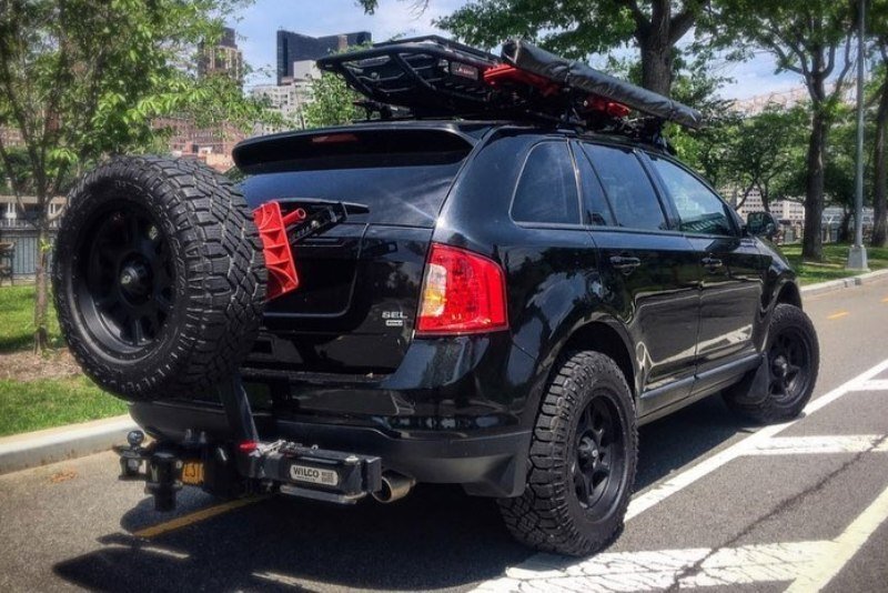
If your vehicle is equipped with a trailer hitch, there is always room on the Back Porch... From Basecamp Brooklyn Good luck!
-

2010 Edge power tailgate problems.
Haz replied to Hodgie's topic in Glass, Lenses, Lighting, Mirrors, Sunroof (BAMR), Wipers
For future reference here, from the 2010 Edge Workshop Manual... Placing your device cursor over underlined acronyms may yield full-words descriptions of the acronyms. Power Liftgate Initialization NOTE: The power liftgate may not operate correctly under the following conditions: If any of these conditions has occurred, the power liftgate must be reinitialized. A low voltage or dead battery A disconnected battery Repairs/adjustments have been made to the power liftgate rod, power liftgate motor, liftgate hinges or liftgate striker NOTE: Battery power must be removed from the Liftgate/Trunk Module (LTM) for 20 seconds before the LTM will enter the initialization mode. Disconnect the battery or remove the LTM fuse(s). Wait 20 seconds and reconnect the battery or reinstall the LTM fuse(s). If liftgate is not already in the fully closed position, manually close and fully latch the power liftgate. NOTE: Make sure the power liftgate system is turned ON in the message center before performing this step. NOTE: If the power liftgate does not open during this step, refer to the Symptom Chart to diagnose the inoperative power liftgate. Power open the power liftgate by using the key fob or control switch. Once the power liftgate is fully open, close the power liftgate by using the key fob or control switch. Good luck! -
Welcome to the Forum, @ODPILOT! I had a peculiar and somewhat comparable experience with Forscan and my laptop communicating through our 2015 MKX's Data Link Connector. Intending to monitor a Forscan Dashboard of data points, I started our MKX and began to leave our garage while Forscan was performing its modules scan. While lowering a power window and as the BLIS radar passed the Garage door framing, the window stopped and the BLIS mirror warning lamp remained stuck on. Perplexed, I scanned for DTCs using the then fully-operational Forscan, and several DTCs existed. I cleared those DTCs and the BLISS mirror warning lamp extinguished and power window operation returned. My expectation is Forscan's module communication attempts were interrupted by the activity of the power window and BLIS systems. I'm not immediately familiar with your scanner without downloading and reading its User Guide, but perhaps you can try powering up your scanner with your Edge in Key On Engine Off state -- that is, advancing past Accessory to its Ignition being On, but without performing a Start button push -- since starting your Edge requires brake pedal actuation -- which causes the Powertrain Control Module (PCM) to transmit... Then, try performing a DTC scan to see if any exist, perhaps especially, communications-related "U" codes in the PCM. GWM, or ABS module(s). If any exist, clear them, and see if that extinguishes your Edge's brake lamps. If our MKX hadn't behaved in that past peculiar manner, I wouldn't be offering this advice now. Good luck!








-PowerDistributionWiringDiagramwModuleFuse10HIGHLIGHTED-2016Edge.thumb.jpg.32deb20e56f79b2a1088bc5074a79f80.jpg)
-LocationIllustration-2016Edge.thumb.jpg.8a6c14cec3faea18d122c481c64d9d96.jpg)
-IllustrationHIGHLIGHTINGRED-BoxedLGTMFuse10Location-2016Edge.thumb.jpg.b29b76f053aa23aebd8b401e712b38f6.jpg)


-BrakePedalPosition(BPP)Fuse54Red-CircledInIllustration-2015Edge.thumb.jpg.5a9ec136fd7373bfff6eb0c2b70d230d.jpg)
