
Haz
Edge Member-
Posts
1,350 -
Joined
-
Last visited
-
Days Won
357
Content Type
Profiles
Forums
Gallery
Everything posted by Haz
-
Fuses and Fuse Box Locations - 2024 Nautilus Owner's Manual.pdf Central Junction Box (CJB) - Fuse-Relay Locations - 2024 Nautilus.pdf Central Junction Box (CJB) - Fuses-Circuits Listing #1 - 2024 Nautilus.pdf Central Junction Box (CJB) - Fuses-Circuits Listing #2 - 2024 Nautilus.pdf Central Junction Box (CJB) - Fuses-Circuits Listing #3 - 2024 Nautilus.pdf Central Junction Box (CJB) - Connector C2281A & C2281B Locations - 2024 Nautilus.pdf Central Junction Box (CJB) & Connectors C2281A & C2281B Location - 2024 Nautilus.pdf Battery Junction Box (BCMC) & High Current Battery Junction Box (BJB) Illustration - 2024 Nautilus.pdf Battery Junction Box (BCMC) - Fuses-Circuits Listing #1 - 2024 Nautilus.pdf Battery Junction Box (BCMC) - Fuses-Circuits Listing #2 - 2024 Nautilus.pdf Battery Junction Box (BCMC) - Fuses-Circuits Listing #3 - 2024 Nautilus.pdf Battery Junction Box (BCMC) Illustration & Connectors C1035A & C1035B Location - 2024 Nautilus.pdf Battery Junction Box (BCMC) Illustration & Connectors C1035A & C1035B Location - 2024 Nautilus.pdf Low Voltage High Current Fuse - 2.0L EcoBoost - Removal and Installation - 2024 Nautilus Workshop Manual.pdf Battery Junction Box (BCMC)) - Removal and Installation - 2024 Nautilus Workshop Manual.pdf
-
Attached below as PDF documents are Adaptive Cruise Control sections from the 2022 Edge Workshop Manual... Good luck! Adaptive Cruise Control - System Operation and Component Description - 2022-2024 Edge Workshop Manual.pdf Module Configuration - System Operation and Component Description - 2022-2024 Edge Workshop Manual.pdf Cruise Control Radar Alignment - General Procedures - 2022-2024 Edge Workshop Manual.pdf Cruise Control Module (CCM) - Removal and Installation - 2022-2024 Edge Workshop Manual.pdf Front Bumper Cover - Removal and Installation - 2022-2024 Edge Workshop Manual.pdf
-
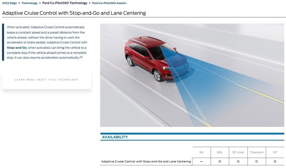
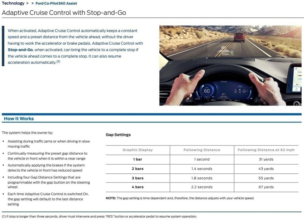
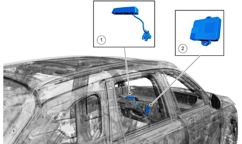
Welcome to the Forum, @SV101! Presumably, your dealer found evidence on the bumper cover and/or the Cruise Control Module (CCM) that the bracket breakage and ruined CCM was the result of a collision of some sort. Electronic modules that have been physically dropped are always to be replaced, so if the CCM suffered an impact sufficient to fracture its mounting bracket, then the CCM must be replaced. You are not being "ripped off". The following images describe the auto-braking feature your Edge's optional Co-Pilot 360 package provides... You may want to explore submitting a claim to have the repair cost paid under the collision coverage of your auto insurance. Good luck!
-

Customer Satisfaction 22N12- Flex Plate Crack on 2.0
Haz replied to All Hat No Cattle's topic in Recalls, TSBs & Warranty
The CSP-designated replacement flexplate (1S7Z-6375-D) is shown as replacing two previous flexplate part numbers (1L8Z-6375-AA and 1S7Z-6375-B). So, engineering improvement (EI) changes to the previous part numbers have likely occurred. Good luck! -
Just in case, interior mirror Workshop Manual section is attached below as a PDF document... Good luck! Interior Rear View Mirror - Removal and Installation - 2007 Edge Workshop Manual.pdf
-

Installing keyless entry keypad KB3Z-14A626-B
Haz replied to SandyT's topic in Alarms, Keyless Entry, Locks & Remote Start
Welcome to the Forum, @SandyT! 2020 to current Model Year - Wireless RF Key Pad Instructions are attached below as a PDF document... Per the instructions, KB3Z-14A626-B is for vehicles built with factory remote start. Good luck! Multiple Vehicle Lines - With Keyless Remote Entry System.pdf Wireless RF Key Pad Diagnosis Guide.pdf- 1 reply
-
- 2
-

-
SSM 52697 2024 Nautilus - "Blind Spot System Fault" And "Cross Traffic System Fault" Displayed In The Message Center With DTC B159C:78 In The SODR Some 2024 Nautilus vehicles may exhibit "Blind Spot System Fault" and "Cross Traffic System Fault" displayed in the message center with diagnostic trouble code (DTC) B159C:78 stored in the side obstacle detection control module RH (SODR). If this condition occurs, follow Pinpoint Test M in section 419-04B Side and Rear Vision of the Workshop Manual. If diagnosis leads to the removal of the rear bumper cover, inspect the inside of the bumper cover for any labels near the location of the SODR that may be blocking its field view and remove if found. If no labels are found blocking the SODR, continue with normal diagnosis.
-
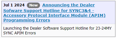
Announcing: Dealer Software Support (DSSH) Hotline for SYNC3 & SYNC4 - Accessory Protocol Interface Module (APIM) Programming Errors Target Dealer Group: All Ford & Lincoln Dealers Target Audience: Dealers, General Managers, Fixed Operations Directors, Service Managers, Parts Managers, Service Advisors, Technicians; Target Dept(s): New Sales, Used Sales, Ford Pro, Finance, Parts, Service, Model e, Warranty, Training; ACTION REQUESTED • Ensure your service teams are aware of the new Dealer Software Support Hotline for SYNC 3 & 4 – Accessory Protocol Interface Module (APIM) Programming errors • To engage, Technicians and vehicles will need to be available to assist with diagnosis • Technicians will be asked to provide a phone number that provides direct access to them to support the Rapid Response SUMMARY Software Diagnosis & Repair Is A Pain Point for our dealers and our customers. Vehicle software related repairs are difficult for dealerships and technicians. Complicating factors include loading software updates, intermittent SYNC issues, and the significant time the technical assistance escalation process can add to repair completion. Ford is committed to improving responsiveness and support for these repairs. DETAILS Program Launch Guidelines Ford will provide a dedicated team to man a Dealer Software Support Hotline (DSSH) that has support from a cross-functional team of Ford experts for software-related concerns. This Hotline is to be used for: • 2023 & 2024 MY vehicles with SYNC-related concerns • DSSH team will provide: • Enhanced rapid response to Technical Support Requests (TSR) related to SYNC diagnosis and repair, with the following goals:. • Initial response to TSR within 15 minutes • Repair direction provided within 4 business hours • Objective to resolve within 2 business days • Module programming support for SYNC modules (APIM) • Repair guidance for replacement of SYNC modules (APIM) Dealer Partner Request The DSSH program will launch with all Ford and Lincoln dealerships. As participating dealership partners: • Ensure normal diagnosis and internal escalation have been completed prior to submitting SYNC-related concerns, using a single point of contact to submit for help via a TSR What Is Changing • SYNC TSRs will be routed directly to the DSSH team for rapid diagnosis and development ofrepair solutions • Requesting technician & vehicle availability to discuss concern • Requesting a phone number with direct access to technician • Access to manually generated Repair Validation Codes (RVCs) will be removed - RVCs will be provided by the DSSH team. Note: Automatic RVCs generated via SYNC Guided Diagnostics remains in place. • SYNC Engineering support is prioritizing diagnosis of complex concerns and prevention of recurrence of systemic issues RESOURCES • SSM 52675 -- SYNC3 - Accessory Protocol Interface Module (APIM) Programming Error... SSM 52675 2019-2024 Various Vehicles - SYNC 3 - Accessory Protocol Interface Module (APIM) Programming Error - "INSTL_ERR12" Using FDRS Or Stuck On "Updating System Software" Or No Response From The Vehicle When Using The Universal USB Updater Some 2019-2024 vehicles equipped with SYNC 3 may experience a programming Error - "INSTL_ERR12" while programming APIM using the Ford Diagnosis and Repair System, or experience a frozen screen which says "updating system software" or no progress/response from module using the universal USB updater. This may be due to low memory in the APIM commonly occurring on software level NU5T-14G381-AB/BB. The current software level can be verified checked in the SYNC tab of PTS, or using the center display screen, Settings > General > About. To correct the condition run the universal USB updater. If unsuccessful, using the latest software version of the Ford Diagnosis and Repair System (FDRS) scan tool, run the service function "APIM - Reset the Accessory Protocol Interface Module Application" and select "Clear All User Data" option. The center display screen will reboot. As soon as module reboot is detected, immediately initiate APIM module programming by inserting the universal USB updater. The APIM Screen should display "successful APIM update" when complete. If process does not complete as expected, retry 1x.If the concern persists, then raise a Technical Support Request for assistance. Do not replace the APIM prior to contacting Technical Support.
-

Disappoinment - PTU drain and fill - capacity
Haz replied to flymore's topic in All Wheel Drive (AWD)
Additional documents... Good luck! Transfer Case - 2.7L EcoBoost - Transfer Case Fluid Level Check - 2017 Edge Workshop Manual.pdf Transfer Case Input Shaft Seal - 2.7L EcoBoost - Removal and Installation - 2017 Edge Workshop Manual.pdf Transfer Case Vent - 2.7L EcoBoost - Removal and Installation - 2017 Edge Workshop Manual.pdf -

Disappoinment - PTU drain and fill - capacity
Haz replied to flymore's topic in All Wheel Drive (AWD)
When the Workshop Manual diagnosis and testing section mentions Transmission Fluid leakage, it initially describes external-to-the Transfer Case leaks, not Transmission Fluid passing into the Transfer Case, however, under Analysis of Leakage, overfilled PTU fluid is assigned to a need for replacement of intermediate and input shaft seals (emphasis added) ... Analysis of Leakage (Partial) The power transfer unit may leak different color fluids, automatic transmission fluid and a brown/black gear lube for power transfer unit fluid. The power transfer unit seals prevent these types of fluids from leaking. Its important to note the color of fluid leaking to determine the most appropriate service procedure. NOTE: Remove and replace leaking seals using the information found in the appropriate procedure. The specified tools called out in this procedure allows seal replacement without causing damage to the power transfer unit casing/drive gear. NOTE: Replace the intermediate shaft seal any time the intermediate shaft is removed. Power Transfer Unit Leaks From the LH Side If the leak is automatic transmission fluid, the compression seal needs to be replaced. REFER to: Transfer Case (308-07C Transfer Case - 2.7L EcoBoost (238kW/324PS), Removal). REFER to: Intermediate Shaft Seal (308-07C Transfer Case - 2.7L EcoBoost (238kW/324PS), Removal and Installation). If the PTU fluid is overfilled, replace the intermediate shaft seal, LH input shaft seal and the RH input shaft seal. REFER to: Transfer Case Input Shaft Seal (308-07C Transfer Case - 2.7L EcoBoost (238kW/324PS), Removal and Installation). REFER to: Intermediate Shaft Seal (308-07C Transfer Case - 2.7L EcoBoost (238kW/324PS), Removal and Installation). Related Workshop Manual sections are attached below and in an immediately following post as PDF documents... Transfer Case - 2.7L EcoBoost - Diagnosis and Testing - 2017 Edge Workshop Manual.pdf Transfer Case - 2.7L EcoBoost - Removal - 2017 Edge Workshop Manual.pdf Transfer Case Intermediate Shaft Seal - 2.7L EcoBoost - Removal and Installation - 2017 Edge Workshop Manual.pdf Transfer Case Intermediate Shaft Bushing - 2.7L EcoBoost - Removal and Installation - 2017 Edge Workshop Manual.pdf Transfer Case - 2.7L EcoBoost - Power Transfer Unit - Overview - 2017 Edge Workshop Manual.pdf Transfer Case - 2.7L EcoBoost - Installation - 2017 Edge Workshop Manual.pdf -
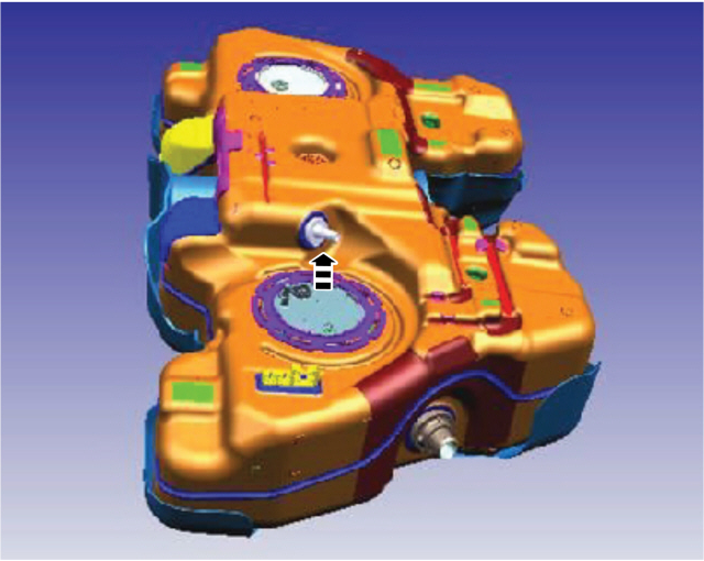
TECHNICAL SERVICE BULLETIN 2.0L - AWD - Various Driveability Symptoms And/Or Illuminated MIL With Evaporative Emissions DTCs After A Refuel Event 24-2199 01 July 2024 Model: Ford 2024 Edge Engine: 2.0L EcoBoost AWD Markets: North American markets only Issue: Some 2024 Edge vehicles equipped with a 2.0L engine and AWD may experience the fuel tank not filling up beyond half-full, hard to start, and/or stalls upon restart after refueling. A MIL with DTC P04F0, P0451, P0455, and/or P0496 may also be stored in the PCM. This may be due to a disconnected fuel vapor line inside the fuel tank. To correct the condition, follow the Service Procedure to reattach the fuel tank vapor line inside the fuel tank. Action: Follow the Service Procedure to correct the condition on vehicles that meet all of the following criteria: • 2024 Edge • 2.0L • AWD • At least one of the following symptoms: - Fuel tank not filling up beyond half-full - Hard to start - Stalls upon restart after refueling Parts Service Part Number Claim Quantity Package Order Quantity Number in Package Description W714265-S442 2 1 4 Exhaust Nut CV6Z-9450-E 1 1 1 Exhaust Gasket F2GZ-4682-A 3 3 1 Driveshaft To PTU Bolts/Straps W790063-S900 3 1 3 Driveshaft To Pinion Bolts/Straps W712154-S439 2 1 4 Center Bearing Bolts 4L3Z-9276-AA 1 1 1 Fuel Pump And Sender Unit Ring CCPZ-3B477-B 2 2 1 Axle Nut K2GZ-9D653-A 1 1 1 Evaporative Emissions Canister W718188-S439 8 2 4 Wheel Bearing And Hub Retainers W715448-S439 2 1 4 Halfshaft Retaining Clip W715624-S439 4 1 4 Caliper Bracket Support Bolt XY-75W-QL As Needed As Needed Motorcraft® Differential Rear Drive Unit Fluid PM-4-A As Needed As Needed Motorcraft® Metal Brake Parts Cleaner (Compliant With Low Volatile Organic Compound Requirements As Required In Some USA States) PM-4-B As Needed As Needed Motorcraft® Metal Brake Parts Cleaner (Not Compliant With Volatile Organic Compound Requirements) Claim Quantity refers to the total number of individual pieces required to repair the vehicle. Package Order Quantity refers to the amount of the service part number package(s) required to repair the vehicle. Number In Package refers to the number of individual pieces included in a service part number package. As Needed indicates the part is necessary but amount of the part may vary and/or is not a whole number. Parts can be billed out as non-whole numbers, including less than 1. Warranty Status: Eligible under provisions of New Vehicle Limited Warranty (NVLW)/Emissions Warranty/Service Part Warranty (SPW)/Service Part New Vehicle (SPNV)/Extended Service Plan (ESP) coverage. Limits/policies/prior approvals are not altered by a TSB. NVLW/Emissions Warranty/SPW/SPNV/ESP coverage limits are determined by the identified causal part and verified using the OASIS part coverage tool. Labor Times Description Operation No. Time 2024 Edge AWD 2.0L EcoBoost: Inspect And Connect Vapor Hose Includes Time To Replace EVAP Canister And Remove And Install Fuel Pump Sender (Do Not Use With Any Other Labor Operations) 242199A 4.9 Hrs. Repair/Claim Coding Causal Part: 9002 Condition Code: 01 Service Procedure 1. Remove the fuel tank assembly. Refer to the WSM, Section 310-01A, Removal and Installation, Fuel Tank. 2. Remove fuel pump and sender unit. Refer to the WSM, Section 310-10A, Removal and Installation, Fuel Pump and Sender. 3. Inspect the inside of the fuel tank for a disconnected fuel vapor hose. (Figures 1-2) Figure 1 Figure 2 4. Is the hose disconnected? (1). Yes - reattach the hose. Proceed to Step 5. NOTE: Do not reinstall the fuel tank until the EVAP canister has been replaced. (2). No - reassemble vehicle and refer to the WSM for normal diagnostics outside of this article. Repair is complete. 5. Replace the EVAP canister. Refer to WSM, Section 303-13A, Removal and Installation, Evaporative Emission Canister. © 2024 Ford Motor Company All rights reserved. NOTE: The information in Technical Service Bulletins is intended for use by trained, professional technicians with the knowledge, tools, and equipment to do the job properly and safely. It informs these technicians of conditions that may occur on some vehicles, or provides information that could assist in proper vehicle service. The procedures should not be performed by "do-it-yourselfers". Do not assume that a condition described affects your car or truck. Contact a Ford or Lincoln dealership to determine whether the Bulletin applies to your vehicle. Warranty Policy and Extended Service Plan documentation determine Warranty and/or Extended Service Plan coverage unless stated otherwise in the TSB article. The information in this Technical Service Bulletin (TSB) was current at the time of printing. Ford Motor Company reserves the right to supersede this information with updates. The most recent information is available through Ford Motor Company's on-line technical resources. TSB 24-2199 and referred-to Workshop Manual sections are attached below as PDF documents... TSB 24-2199 - 2.0L EcoBoost - AWD - Various Driveability Symptoms And-Or Illuminated MIL With Evap Emissions DTCs After A Refuel Event.pdf Fuel Tank - Removal and Installation - 2022-2024 Edge Workshop Manual.pdf Fuel Pump and Sender Unit - Removal and Installation - 2022-2024 Edge Workshop Manual.pdf Evaporative Emission Canister - Removal and Installation - 2022-2024 Edge Workshop Manual.pdf
-
Welcome to the Forum, @Terrible Tim! Relevant sections from the 2011 Edge Workshop Manual and Wiring Resource are attached below as PDF documents... If your diagnostic efforts progress to you requiring electrical connector information, I can supply that as well. Good luck! Front Park-Turn Lamps - Wiring Diagram - 2011 Edge.pdf Park-Turn Lamps, Left Hand - Fuse F14 - Wiring Diagram - 2011 Edge.pdf Park-Turn Lamps, Right Hand - Fuse F13 - Wiring Diagram - 2011 Edge.pdf Body Control Module (BCM) - Fuse Location Diagram - 2011 Edge.pdf Body Control Module (BCM) - Fuse-Circuits Listing - 2011 Edge.pdf Turn Signal and Hazard Lamps - Diagnosis and Testing - 2011 Edge.pdf Parking, Rear and License Plate Lamps - Diagnosis and Testing - 2011 Edge.pdf HID Headlamps - Wiring Diagram - 2011 Edge.pdf Adaptive Headlamps - Wiring Diagram - 2011 Edge.pdf Headlamps - Diagnosis and Testing - 2011 Edge.pdf
- 1 reply
-
- 1
-

-
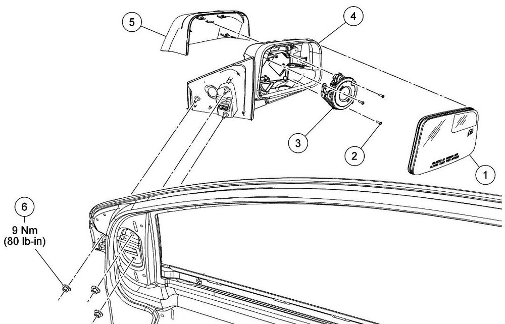
Should the need arise, 2014 Edge Workshop Manual procedures to disassemble and/or remove exterior mirror from vehicle are attached below as a PDF documents... Good luck! Exterior Mirror - Removal and Installation - 2014 Edge Workshop Manual.pdf Exterior Mirror Cover - Removal and Installation - 2014 Edge Workshop Manual.pdf Exterior Mirror Glass - Removal and Installation - 2014 Edge Workshop Manual.pdf Exterior Mirror Motor - Removal and Installation - 2014 Edge Workshop Manual.pdf
-
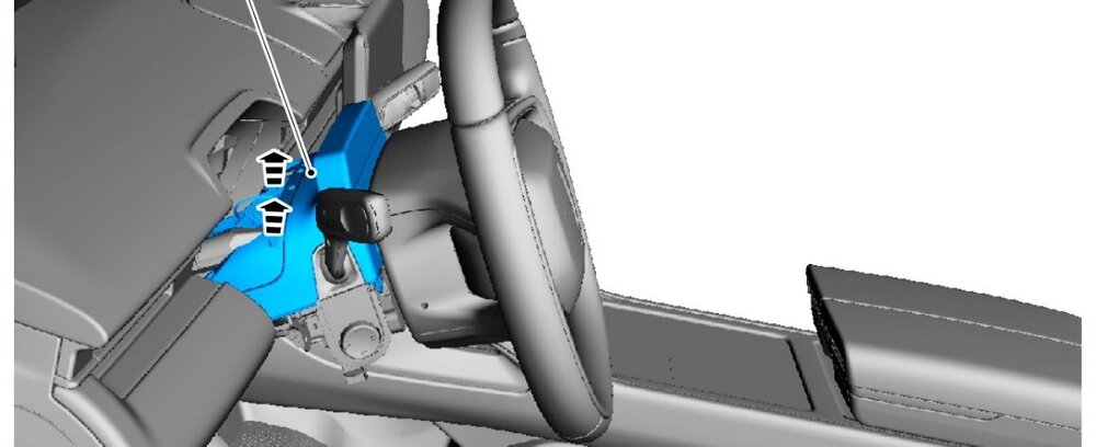
SSM 52680 2024 Nautilus - Driver Status Monitor Camera Off-Center The driver status monitor camera in some 2024 Nautilus vehicles may be positioned off-center on the top of the steering column shroud. The steering column and shrouds normally rotate back and forth due to its tilt and telescopic feature. Assure any customers who report this concern that it does not affect Blue Cruise function. If this condition occurs, do not manually twist the driver status monitor camera to center it. Telescoping the steering column out all the way out and then all the way in should center the driver status monitor camera with no repairs needed. The steering column position can then be set to the customer's preference. Supplement illustrations from 2024 Nautilus Workshop Manual... Interior Camera System - Component Locations
- 1 reply
-
- 2
-

-
From the 2020 Edge Owner's Manual, United Kingdom (UK) version... Lighting - Glare-Free High Beam (If Equipped) GLARE-FREE HIGH BEAM (IF EQUIPPED) WARNING: The system does not relieve you of your responsibility to drive with due care and attention. You may need to override the system if it does not turn the high beams on or off. WARNING: You may need to override the system when approaching other road users. WARNING: You may need to override the system during inclement weather. WARNING: Do not use the system in poor visibility, for example fog, heavy rain, spray or snow. WARNING: The system may not adapt the high beams to avoid glare if the lights of oncoming vehicles are hidden by obstacles, for example guard rails. WARNING: Inspect and replace the windshield wiper blades regularly to make sure the camera sensor has a clear view. The windshield wiper blades must be the correct length. About Glare-Free High Beam The system is designed to prevent you from distracting other road users when the high beams are on. ANormal High Beam. BGlare-Free High Beam. The system is designed to turn the high beams on if all of the following occur: You switched the system on in the information display. You set the lighting control to the autolamps position. The ambient light level is low enough that high beams are required. Your vehicle speed is greater than approximately 40 km/h (25 mph). The system is designed to adapt the high beams to avoid glare if all of the following occur: You switched the system on in the information display. You set the lighting control to the autolamps position. The system detects an approaching vehicle's headlamps or rear lamps. The high beam headlamp indicator remains on when the system adapts the high beams to avoid glare. The system is designed to turn the high beams off if any of the following occur: You switch the system off in the information display. You set the lighting control to any position except autolamps. You switch the rear fog lamps on. The system detects severe rain, snow or fog. The system detects street lighting. The camera has reduced visibility. Your vehicle speed falls below approximately 30 km/h (19 mph). The deactivation speed is lower on curves. Switching Glare-Free High Beam On or Off To switch the system on or off, use the information display controls on the steering wheel to select the following: Menu Item Action Settings Press the OK button. Vehicle Press the OK button. Lighting Press the OK button. Auto Highbeam Press the OK button. Glare-Free High Beam Indicator It illuminates to confirm when the system is ready to assist. Overriding Glare-Free High Beam Push the lever away from you to switch between high beam and low beam. UK Headlamp adjustment procedures attached below as PDF documents... Good luck! Headlamp Adjustment - Vehicles Built Up To 6-September-2018 - 2015 - 2022 Edge, Edge Vignale, Endura Workshop Manual - United Kingdom.pdf Headlamp Adjustment - Vehicles Built From 6-September-2018 - 2015 - 2022 Edge, Edge Vignale, Endura Workshop Manual - United Kingdom.pdf Headlamp Adjustment - Specifications - 2015 - 2022 Edge, Edge Vignale, Endura Workshop Manual - United Kingdom.pdf
-
Welcome to the Forum @Snub_Nose_Edge! To provide you a glimpse of the scope of work involved in TSB 23-2346/TSB 23-2049, attached below as PDF documents are some -- but not all -- of 2020 Edge Workshop Manual sections involved in performing the repair... Please note that some of the numbered action-step descriptions which precede their associated illustrations may appear on the page before their rightfully associated illustrations. I invite other Forum members to respond to your additional questions. Variable Camshaft Timing (VCT) Unit - Removal and Installation - 2.7L EcoBoost - 2020 Edge Workshop Manual.pdf Timing Chain - Removal and Installation - 2.7L EcoBoost - 2020 Edge Workshop Manual.pdf
-
SSM 52647 2024 Nautilus - Unable To Clear Diagnostic Trouble Code (DTC) U3000:52 From APIM After Replacement Some 2024 Nautilus vehicles equipped with Sirius XM® satellite radio may exhibit a concern where a technician is unable to clear DTC U3000:52 from the accessory protocol interface module (APIM) after replacement. This may be due to SiriusXM® software falsely reporting the SiriusXM® subscription activation status. Replacement or reprogramming of the APIM will not resolve this condition. DTC U3000:52 should be ignored if the SiriusXM® radio is operational, allowing access to the Channel 0 tile, displaying the SiriusXM Radio ID, the user can tune to the Preview Channel 1 with or without a subscription, and no other DTCs are present in the APIM or warning lights are illuminated. No further service action is required.
-

Clunk coming from rear middle of 19 Edge when accelerating?
Haz replied to eric1's topic in 2019-2020 Edge & Nautilius
Welcome to the Forum @T Griff! You may want to add your experience to this discussion... Edge Low Speed Surge/Buck - Transmission Good luck! -

Clunk coming from rear middle of 19 Edge when accelerating?
Haz replied to eric1's topic in 2019-2020 Edge & Nautilius
From the 2019 Edge Workshop Manual... Related sections of the 2019 Edge Workshop Manual are attached below as PDF documents... Good luck! Driveshaft - Diagnosis and Testing - 2019 Edge Workshop Manual.pdf Rear Driveshaft - 2.0L EcoBoost - Removal and Installation - 2019 Edge Workshop Manual.pdf Rear Driveshaft - 2.7L EcoBoost - Removal and Installation - 2019 Edge Workshop Manual.pdf -
This Special Service Message was issued in September, 2020... SSM 49156 2017-2020 Various Vehicles - Speed Compensated Volume Operation Some 2017-2020 Ford and Lincoln vehicles may exhibit a customer concern of a perceived inoperative or reduced speed compensated volume function. Do not compare speed compensated volume operation with other vehicles as system operation varies between vehicle lines, model years and audio systems. To determine if the system is operating properly, drive the vehicle at constant highway speeds with the audio system at a medium to high volume level and switch the speed compensated volume system setting from off > high > off. If an increase in volume is observed when switching the system from off > high the system is operating properly. If there is no discernible change, refer to Workshop Manual (WSM), Section 415-00 for further diagnostics. The following information is from the 2019 Edge Workshop Manual... Audio Front Control Module (ACM) Operation The ACM receives vehicle speed information, used to adjust audio volume with different vehicle speeds, from the PCM over the CAN . PINPOINT TEST F: THE SPEED COMPENSATED VOLUME DOES NOT OPERATE CORRECTLY Introduction Normal Operation and Fault Conditions REFER to: Information and Entertainment System - Overview (415-00 Information and Entertainment System - General Information, Description and Operation). Possible Causes Speed compensated volume setting Speed signal concern Network communication concern ACM F1 CHECK THE SPEEDOMETER OPERATION Verify speedometer operates correctly. Does the speedometer operate correctly? Yes GO to F2 No REFER to: Instrumentation, Message Center and Warning Chimes (413-01 Instrumentation, Message Center and Warning Chimes, Diagnosis and Testing). F2 CHECK THE SPEED COMPENSATED VOLUME SETTING NOTE: Refer to the Owner Literature to access the speed compensated volume settings. Turn the speed compensated volume off. Operate the audio system in AM / FM mode. Drive the vehicle at various speeds and observe the speaker volume. Set the speed compensated volume to maximum compensation. Operate the audio system in AM / FM mode. Drive the vehicle at various speeds and observe the speaker volume. Does the volume remain constant with the speed compensated volume turned off, and increase and decrease with vehicle speed with the speed compensated volume set to maximum? Yes The system is operating correctly at this time. INFORM the vehicle owner in the correct usage of the speed compensated volume feature. No GO to F3 F3 CHECK FOR COMMUNICATION DIAGNOSTIC TROUBLE CODES (DTCS) Using a diagnostic scan tool, carry out the ACM self-test. Are any Diagnostic Trouble Codes (DTCs) present? Yes REFER to the ACM DTC Chart in this section. No For vehicles equipped with the 6 or 9 speaker system, GO to F5 For vehicles equipped with the 12 speaker system, GO to F4 F4 CHECK FOR CORRECT DSP (AUDIO DIGITAL SIGNAL PROCESSING MODULE) OPERATION Ignition OFF. Disconnect and inspect all the DSP connectors. Repair: Corrosion (clean module pins or install new connectors or terminals) Damaged or bent pins (install new terminals or pins) Pushed-out pins (install new pins as necessary) Reconnect the DSP connectors. Make sure they seat and latch correctly. Operate the system and determine if the concern is still present. Is the concern still present? Yes CHECK OASIS for any applicable service articles: TSB , GSB , SSM or FSA . If a service article exists for this concern, DISCONTINUE this test and FOLLOW the service article instructions. If no service articles address this concern, INSTALL a new DSP . REFER to: Audio Digital Signal Processing (DSP) Module (415-00 Information and Entertainment System - General Information, Removal and Installation). No The system is operating correctly at this time. The concern may have been caused by module connections. ADDRESS the root cause of any connector or pin issues. F5 CHECK FOR CORRECT ACM (AUDIO FRONT CONTROL MODULE) OPERATION Ignition OFF. Disconnect and inspect all the ACM connectors. Repair: Corrosion (clean module pins or install new connectors or terminals) Damaged or bent pins (install new terminals or pins) Pushed-out pins (install new pins as necessary) Reconnect the ACM connectors. Make sure they seat and latch correctly. Operate the system and determine if the concern is still present. Is the concern still present? Yes CHECK OASIS for any applicable service articles: TSB , GSB , SSM or FSA . If a service article exists for this concern, DISCONTINUE this test and FOLLOW the service article instructions. If no service articles address this concern, INSTALL a new ACM . REFER to: Audio Front Control Module (ACM) (415-00 Information and Entertainment System - General Information, Removal and Installation). No The system is operating correctly at this time. The concern may have been caused by module connections. ADDRESS the root cause of any connector or pin issues. The above Pinpoint Test and several referenced 2019 Edge Workshop Manual sections are attached below as PDF documents if fuller diagnostic efforts are necessary... Good luck! DIAGNOSTIC PINPOINT TEST ''F'' - THE SPEED COMPENSATED VOLUME DOES NOT OPERATE CORRECTLY - 2019 Edge Workshop Manual.pdf Audio Digital Signal Processing (DSP) Module - Removal and Installation - 2019 Edge Workshop Manual.pdf Audio Front Control Module (ACM) - Removal and Installation - 2019 Edge Workshop Manual.pdf Front Controls Interface Module (FCIM) - Removal and Installation - 2019 Edge Workshop Manual.pdf Front Display Interface Module (FDIM) - Removal and Installation - 2019 Edge Workshop Manual.pdf Loadspace Trim Panel - Removal and Installation - 2019 Edge Workshop Manual.pdf
-
Additional documents... Good luck! Inline Harness Connector - Connector C214 Location - 2020 Edge.pdf Inline Harness Connector - Connector C214 Pins-Circuits Detail - 2020 Edge.pdf Audio Digital Signal Processing (DSP) Module - Removal and Installation - 2020 Edge Workshop Manual.pdf Front Controls Interface Module (FCIM) - Removal and Installation - 2020 Edge Workshop Manual.pdf Front Display Interface Module (FDIM) - Removal and Installation - 2020 Edge Workshop Manual.pdf Audio Front Control Module (ACM) - Removal and Installation - 2020 Edge Workshop Manual.pdf
-
Regarding your interest in a true switched power source, perhaps the AM/FM Antenna Amplifier power circuit can provide you what you're seeking, since I expect the antenna amplifier would only be powered when the audio system is operating. Relevant sections from the 2020 Edge Workshop & Wiring Manuals are attached as PDF documents below and in an immediately following post, due to Forum file attachment limitations... Inline Harness Connector - Connector C411 Location Alternative View - 2020 Edge.pdf Audio Front Control Module (ACM) - Connector C240A - Location - 2020 Edge.pdf Inline Harness Connector - Connector C411 Location - 2020 Edge.pdf Inline Harness Connector - Connector C411 Pins-Circuits Detail - 2020 Edge.pdf AM-FM1 Antenna Amplifier Power - Connector C9021A Location - 2020 Edge.pdf AM-FM1 Antenna Amplifier Power - Connector C9021A Pin-Circuit Details - 2020 Edge.pdf Audio Front Control Module (ACM) - Wiring Diagram - 2020 Edge.pdf AM-FM1 Antenna Amplifier - Removal and Installation - 2020 Edge Workshop Manual.pdf Audio Front Control Module (ACM) - Connector C240A - Pins-Circuits Details - 2020 Edge.pdf
-
The front license plate requirement in Ohio was eliminated on July 1, 2020, so there's no need to mount it, unless your wife has a personalized aftermarket plate for her new Edge. With that said, the bracket is pop-riveted to the upper bumper cover, on center with the grille's Ford logo... Good luck!

