Haz
-
Posts
1,460 -
Joined
-
Last visited
-
Days Won
392
Everything posted by Haz
-
LED strip lights 2013 Edge SE
Haz replied to BraddB's topic in Glass, Lenses, Lighting, Mirrors, Sunroof (BAMR), Wipers
So, they come on with the parking lights, or only when using the toggle switch? Congrats on your perseverance, regardless. Good luck! -
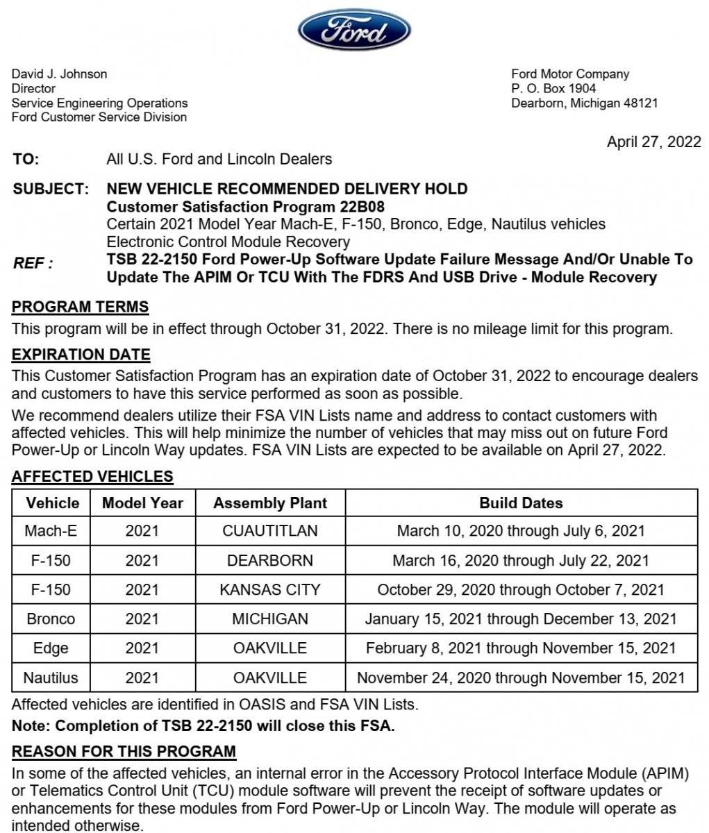
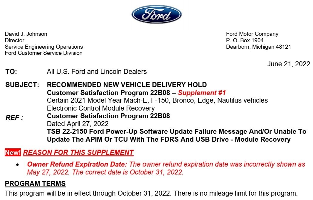
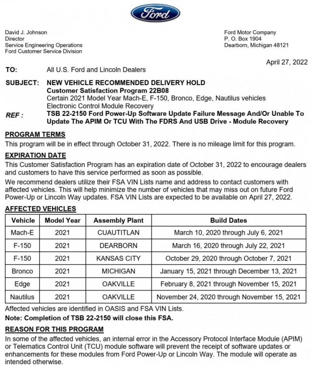
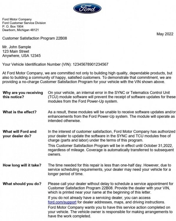
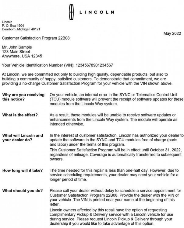
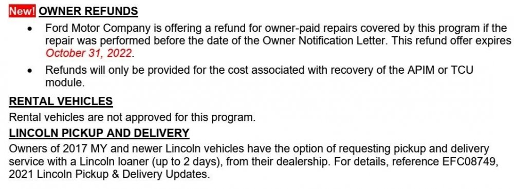
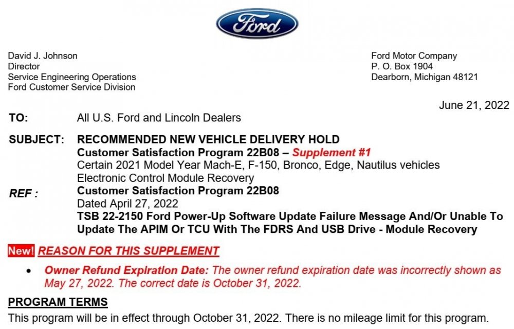
Program Summary Edited For Forum Members... Dealer Notification Letter... Ford Owner Notification Letter... Lincoln Owner Notification Letter... Good luck!

-
Since you've been to the Sync Update Download Page, your thumb drive format is FAT32 for pre-Version 3 Sync system update? If you do not have Navigation, you could use an SD card for your audio files. I use a 2 GB card formatted FAT32 for mp3 files with no issues. Good luck!
-
LED strip lights 2013 Edge SE
Haz replied to BraddB's topic in Glass, Lenses, Lighting, Mirrors, Sunroof (BAMR), Wipers
Good luck!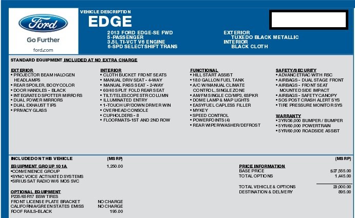
-
LED strip lights 2013 Edge SE
Haz replied to BraddB's topic in Glass, Lenses, Lighting, Mirrors, Sunroof (BAMR), Wipers
It is possible the SE chrome-finish grille has been dipped or painted to mimic the Sport-model appearance. Good luck! -
LED strip lights 2013 Edge SE
Haz replied to BraddB's topic in Glass, Lenses, Lighting, Mirrors, Sunroof (BAMR), Wipers
Do your Edge's wheels match those in the image you posted? If you are comfortable providing me the VIN via the Forum's Message system, I'll look it up in Ford's OASIS information system, which is used by dealership Service technicians. Good luck! -
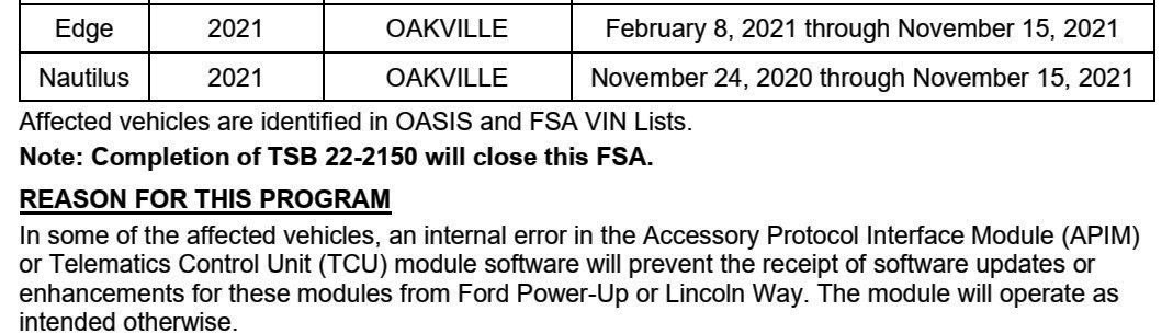
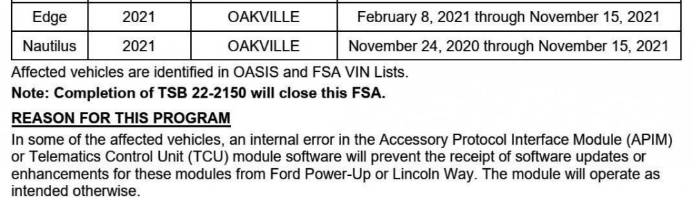
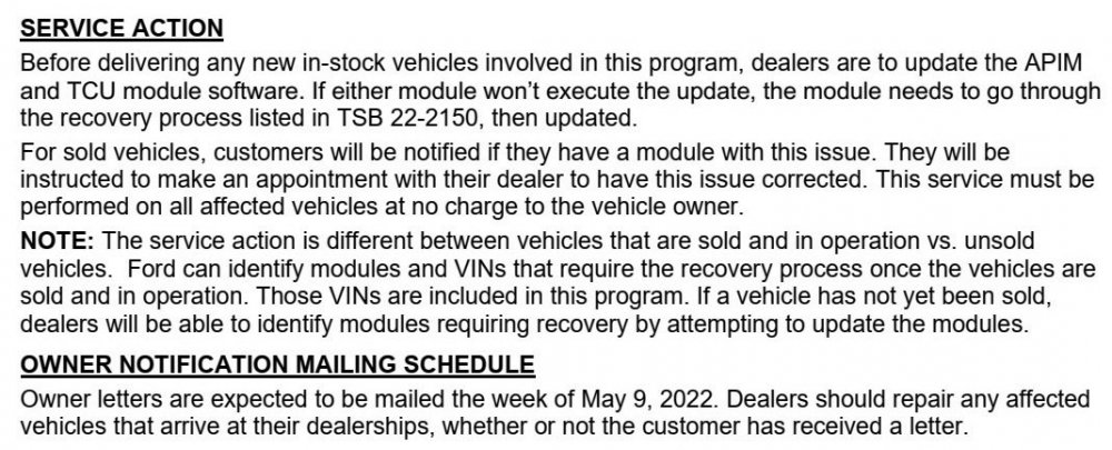
Just noticed this on Ford's Professional Technician System bulletin board... May 9 2022 2021 - 2022 Edge, APIM Software Update Failures The Ford Technical Assistance Center and Ford IT teams are aware that due to server related concerns, APIM programming is failing with an error message stating “Procedure Unsuccesful - GetConfigDataFromGIVIS Modified Configuration data is missing from Ford server". Monitor PTS for updates. If any updates are provided, I'll pass them along. Good luck!
-
LED strip lights 2013 Edge SE
Haz replied to BraddB's topic in Glass, Lenses, Lighting, Mirrors, Sunroof (BAMR), Wipers
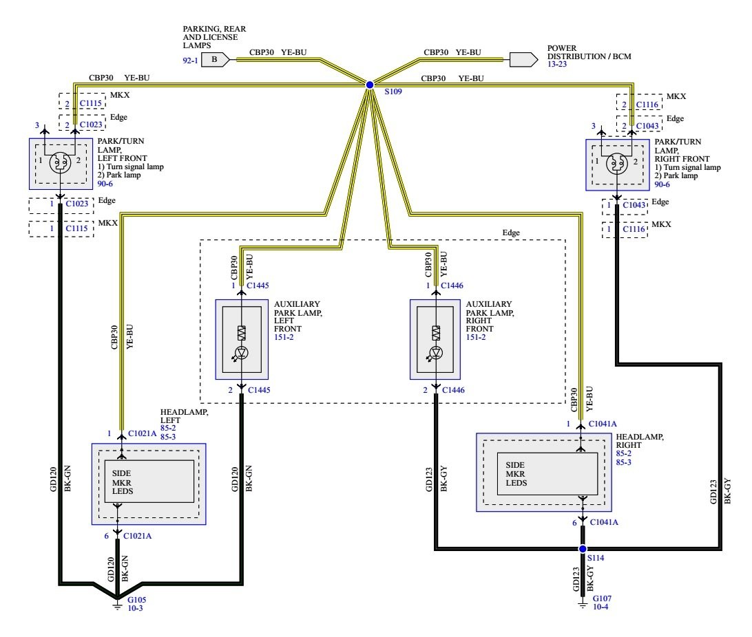
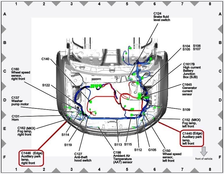
Sympathies to you on your back problems. Back pain has been rare for me, but I appreciate how debilitating it can be. As you're likely aware, the image you shared is a Sport model with its blackout grille, 22-inch wheels, and the LED auxiliary parking lamps as standard equipment. It's worth noting that factory-installed auxiliary parking lamps are wired into the same power-distribution circuit as the front parking lamps & side marker lamps, as well as the rear parking & license plate lamps, per (1004ron's-encouraged) wiring diagram from the 2013 Edge Workshop Manual, included below as an image and a PDF via download link below... On the off-chance that your SE Edge's wiring includes unused plugs for Ford-supplied LED auxiliary parking lamp assemblies. descriptions of wiring connectors used for the left & right side auxiliary parking lamps are included below as PDF download links... If you prefer the installed vertical LED light strips to be on whenever your Edge's parking lamps are lit, you could tap into the front parking/side marker wiring to supply them power. If you prefer to use them as Daytime Running Lights (DRLs), you can troubleshoot the toggle switch circuit, presuming that's how the previous owner installed them to operate. Or you could have both, by tapping into the front parking/side marker wiring to power up the installed LED lights whenever your Edge's parking/tail lamps are lit, and then gain DRLs by asking your dealer to activate your Edge's factory-supplied capability, or do-it-yourself if you or a friend are fluent Forscan-user(s), with the benefit as described in the 2013 Edge Workshop Manual... Daytime Running Lamps (DRL) NOTE: The Daytime Running Lamps (DRL) are a programmable parameter for this vehicle. For vehicles with halogen headlamps: Daytime Running Lamps (DRL) can be enabled/disabled using the BCM Programmable Parameter, DRL Type. the factory selected DRL system operates the low beam headlamps at a reduced intensity. when enabling the DRL using a scan tool, two modes of operation can be selected. The low beam headlamps will illuminate at a reduced intensity (halogen headlamps) or the front turn lamps will illuminate continuously (not flashing) at full intensity. For vehicles with High Intensity Discharge (HID) headlamps: NOTICE: Do not enable Low Beams DRL mode If the vehicle is equipped with High Intensity Discharge (HID) headlamps. If Low Beams DRL mode is enabled, damage to the headlamp ballast may occur. Daytime Running Lamps (DRL) can be enabled/disabled using the BCM Programmable Parameter, DRL Type. the factory selected DRL system operates the front turn lamps illuminate continuously (not flashing) at full intensity. when enabling the DRL using a scan tool, only one mode of operation should be selected. The front turn lamps will illuminate continuously (not flashing) at full intensity. The DRL are activated when the following conditions are met: the ignition is in RUN the headlamps have not been turned on by the autolamp system or the headlamp switch the transmission is not in park Good luck! Auxiliary Parking Lamps Wiring Diagram - 2013 Edge Workshop Manual.pdf Auxiliary Parking Lamp, Right Front C1446 Wiring Connector - 2013 Edge Workshop Manual.pdf Auxiliary Parking Lamp, Left Front C1445 Wiring Connector - 2013 Edge Workshop Manual.pdf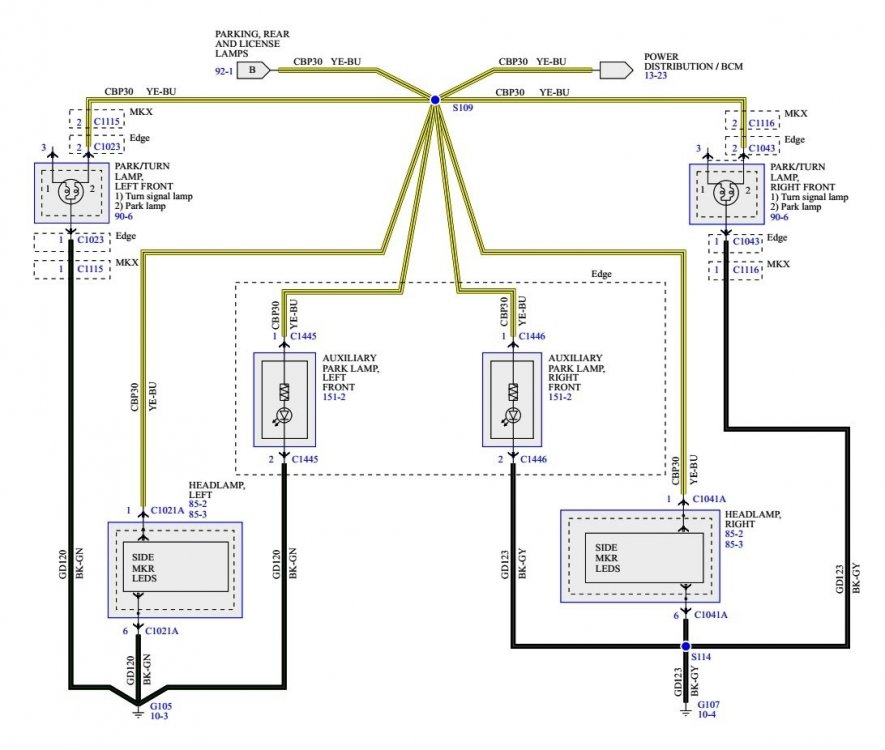
-
LED strip lights 2013 Edge SE
Haz replied to BraddB's topic in Glass, Lenses, Lighting, Mirrors, Sunroof (BAMR), Wipers
The 2013 Edge Sourcebook lists "Parking lamps — supplemental, light-emitting diode (LED)" as standard on SEL trim level, but I do not find any mention of that feature for SE. The SE Convenience Package 101A includes "Autolamp automatic on/off headlamps", but no other exterior lighting feature. Online photos of 2013 SE Edges show a black plastic filler panel where the factory-installed supplemental parking lamp/LED strip is on SEL/Limited/Sport models, as shown in the below image... The LED strips could be actual Ford parts, or aftermarket, installed by a previous owner, and now unsuccessfully controlled by that toggle switch. Look for non-standard wiring and see if what's connected to the LED strips inside the front bumper cover matches the wiring connected to the toggle switch. Good luck!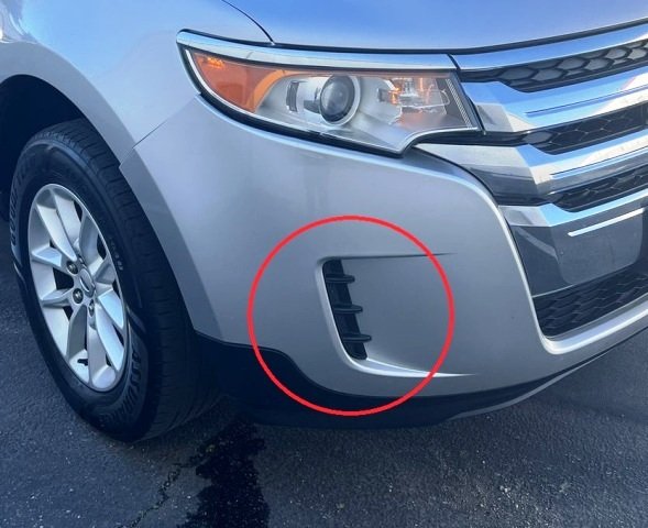
-
I appreciate your photo of the parking brake equalizer arrangement, which the 2010 Edge Workshop Manual describes as... The front parking brake cable is coupled to the LH rear parking brake cable and conduit which is coupled to the RH rear parking brake cable. The parking brake cable and conduits actuate the parking brake levers, engaging the parking brake shoes with the parking brake drum-in-hat assembly. To address your additional question, I lifted the rear end of our 2015 AWD MKX, which is a GEN 1 vehicle like yours, With both rear tires off the floor, and regardless of the transmission being in either Park or Neutral, each wheel rotates freely while the other-side.wheel rotates in the opposite direction, without any noticeable brake pad drag. Good luck!
-
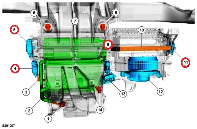
Just to clarify your question, in the case of hot air output on left side and cold air output on right side, is desired goal AC/cold air output temperature on both sides? The following illustration and component listing from the 2015 Edge Workshop Manual shows the location and function of the four actuators you mention... Good luck!
-
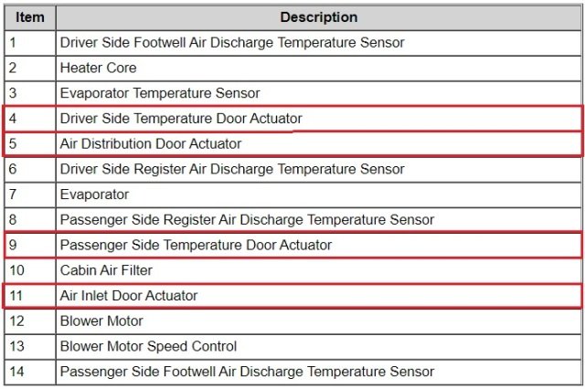
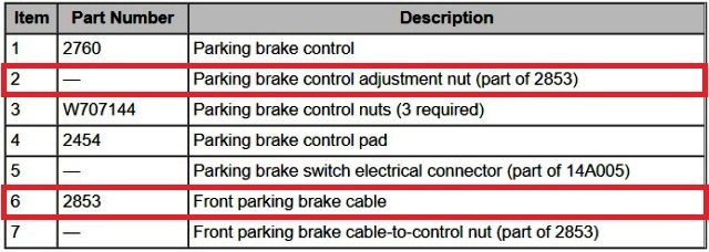
Sorry for inducing information overload with the full set of documents, which hopefully may be helpful to a future reader. You will find In the previously posted Parking Brake Adjustment Workshop Manual PDF document, that Ford immediately specifies that adjustment should be applied equally at both cable-end locations -- at the interior parking brake pedal and at the under-body equalizer. I can only speculate that splitting the total adjustment across both ends of the forward cable may increase its usable life. This illustration shows the location of the interior adjustment nut (2)... Equal turns to the interior pedal adjustment nut and to the under-body equalizer adjustments nut, until you verify a properly holding (and releasing) parking brake by applying the parking brake three times. Good luck!
-
From the 2022 Edge Workshop Manual... Manual APIM Reset Simultaneously press and hold the POWER button (in the middle of the volume button) and the RIGHT SEEK button on the audio controls panel to reboot the APIM . As the APIM reboot begins, the display unit turns black before the startup sequence begins. Good luck!
-
2013 ford edge AWD rear suspension torque specs
Haz replied to thegoose's topic in Brakes, Chassis & Suspension
Below is an illustration of the rear suspension showing the Tow Link and its mounting bolt torque values, as well as PDF download links to relevant sections of the 2013 Edge Workshop Manual... Good luck! Rear Suspension Toe Link Removal and Installation - 2013 Edge Workshop Manual.pdf Rear Suspension Torque Specifications - 2013 Edge Workshop Manual.pdf Suspension General Procedures - Rear Toe Adjustment - 2013 Edge Workshop Manual.pdf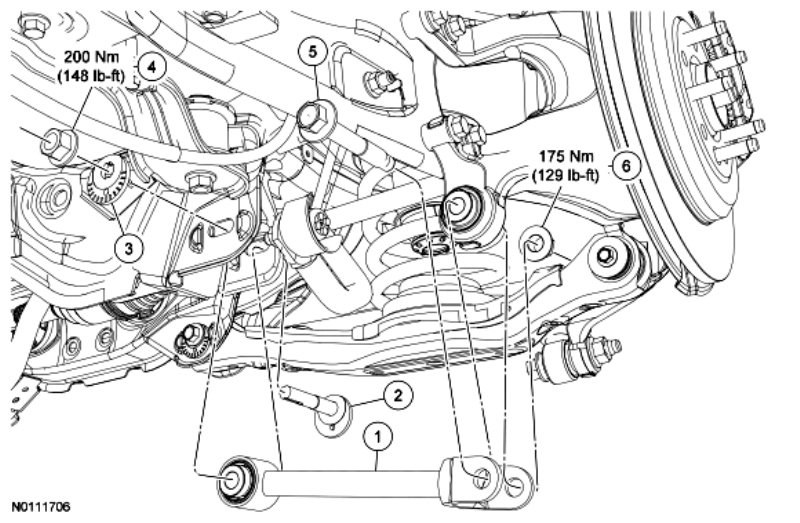
-
The following is from relevant sections of the 2022 Edge Workshop Manual... The Outside Air Temperature Display Is Inoperative or Incorrect Outside Air Temperature - Normal Operation The Ambient Air Temperature (AAT) sensor is hardwired to the PCM through separate input and return circuits. The PCM provides a reference voltage to the Ambient Air Temperature (AAT) sensor and monitors the change in voltage resulting from changes in resistance as determined by outside air temperature. The PCM sends the ambient air temperature data to the GWM through the HS-CAN1 . The GWM sends the ambient air temperature message to the HVAC module over the MS-CAN . The HVAC module filters the data and sends the ambient air temperature filtered data back to the GWM over the MS-CAN . The GWM sends the ambient air temperature filtered message to the IPC over the HS-CAN3 . The HVAC module is programmed to update the messaged outside temperature data at different rates depending on several criteria to prevent false temperature displays due to a condition known as heat soaking. Heat soaking is where the outside air temperature is hotter in the location of the Ambient Air Temperature (AAT) sensor than the actual outside air temperature. The outside air temperature display update strategy requires a starting temperature to update from. This starting temperature is controlled based on the length of time the engine is off and the engine temperature. When the engine has been off for longer than 6 hours, the update strategy begins with the unfiltered ambient air temperature input to the PCM . If the engine has been off for less than 6 hours, and the engine coolant temperature is less than 49° C (120° F), the update strategy begins with the filtered ambient air temperature equal to the unfiltered ambient air temperature. If the engine has been off for less than 6 hours, and the engine coolant temperature is greater than 49° C (120° F), the update strategy begins at the stored previous outside air temperature value. When the sensed outside temperature rises and the vehicle speed is above 33 km/h (21 mph), the outside air temperature display updates after approximately 90 seconds. As the vehicle speed increases, the outside air temperature display updates at a faster rate that is proportional to the increase in vehicle speed. Once the vehicle speeds exceeds 81 km/h (50 mph), the display updates without any delay. If the vehicle speed drops below 33 km/h (21 mph), the update delays reset. When the sensed outside temperature drops, the display updates more quickly following the drop experienced by the Ambient Air Temperature (AAT) sensor. Outside Air Temperature - Fault Conditions If the air ambient temperature message is missing or invalid for less than 5 seconds, the IPC defaults the outside air temperature display to the last temperature reading, based upon the last message received. If the air ambient temperature message is missing or invalid for 5 seconds or longer from the PCM , the IPC displays all dashes (- - ) in the outside air temperature display area. Possible Sources Communication concern Ambient Air Temperature (AAT) sensor input to the PCM GWM concern HVAC module concern You mention that the Outside Air Temperature value is correctly displaying on the right side message center of your Instrument Panel Cluster, which suggests the AAT sensor, Powertrain Control Module, and Gateway Module communication to the Instrument Panel Cluster is good, but that the communication of the Outside Air Temperature value to the Center Stack Touch Screen is missing. Given that your Edge has just 400 miles on it, and the disappearance occurred suddenly, it's possible a wiring connector is not fully seated and the proper data communication to the Center Stack Touch Screen is now interrupted. You also mention the Settings menu does not allow you to change from Metric measurement values to English measurement values, though you don't mention if you're attempting this using the Center Stack Touch Screen, or if any-or-all data values in the display are expressed in Metric measurement. If indeed you're using the Touch Screen to attempt that Settings change, the the lack of success, as you say, may be related to an apparent communications problem, possibly caused by a not-fully-seated electrical connector. As a check on System function, try using your Edge's steering wheel controls to access the Settings menu in the right hand side message center of the Instrument Panel Cluster to change the measurement values from English to Metric and back to English for you IPC. Overcome your (understandable) dread of returning your Edge to the dealership, and give your sales rep a call to see if he-or-she can facilitate scheduling a more prompt Service appointment and loaner-vehicle provision, on your behalf. Your sales rep has a vested interest in you remaining a satisfied dealership customer. Also keep in mind, they are no more happy than you, to be correcting a warranty issue so soon after a vehicle's delivery to its new owner. I checked OASIS to see if any Technical Service Bulletin regarding you concern showed up, but I found none, though I only used model year in my request, and searching by VIN is a more sure method. Good luck!
-
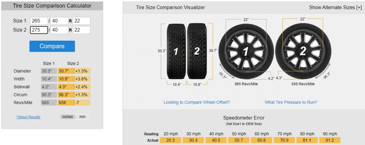
You would do best to follow Pirelli's wheel width recommendation for the specific model of 275/40R22 tire you are contemplating to buy. Many Pirelli tire models show the 9-inch wheel width on your Edge Sport as being the minimum acceptable size for 275/40R22, while a few other Pirelli tire models recommend 10-to-11/12-inch wheel widths. Lincoln provides 9 1/2-inch wide rims for the 275/40R22 tires on its Aviator, which presumably are the minimum for the OEM tire manufacturer. The Tiresize website provides these general statements about your Edge Sport's OEM tire size and the upsized tire you are considering, as well as the comparative graphic, below... Good luck! 265/40R22 tires have a diameter of 30.3", a section width of 10.4", and a wheel diameter of 22". The circumference is 95.3" and they have 665 revolutions per mile. Generally they are approved to be mounted on 9-10.5" wide wheels. Specs may vary by manufacturer 275/40R22 tires have a diameter of 30.7", a section width of 10.8", and a wheel diameter of 22". The circumference is 96.3" and they have 658 revolutions per mile. Generally they are approved to be mounted on 9-11" wide wheels. Specs may vary by manufacturer

-
Below are PDF download links to sections of the 2010 Edge/MKX Workshop Manual relating to the Parking Brake system... Good luck! Parking Brake and Actuation - Diagnosis and Testing - 2010 Edge Workshop Manual.pdf Parking Brake Cable Adjustment - 2010 Edge Workshop Manual.pdf Parking Brake Cable - Front, Removal and Installation - 2010 Edge Workshop Manual.pdf Parking Brake Cable - Rear LH, Removal and Installation - 2010 Edge Workshop Manual.pdf Parking Brake Cable - Rear RH, Removal and Installation - 2010 Edge Workshop Manual.pdf Parking Brake Shoes - Removal and Installation - 2010 Edge Workshop Manual.pdf Brake Disc - Removal and Installation - 2010 Edge Workshop Manual.pdf Parking Brake and Actuation - Torque Specifications - 2010 Edge Workshop Manual.pdf
-
Rear/right turn signal issue
Haz replied to Lenny's topic in Glass, Lenses, Lighting, Mirrors, Sunroof (BAMR), Wipers
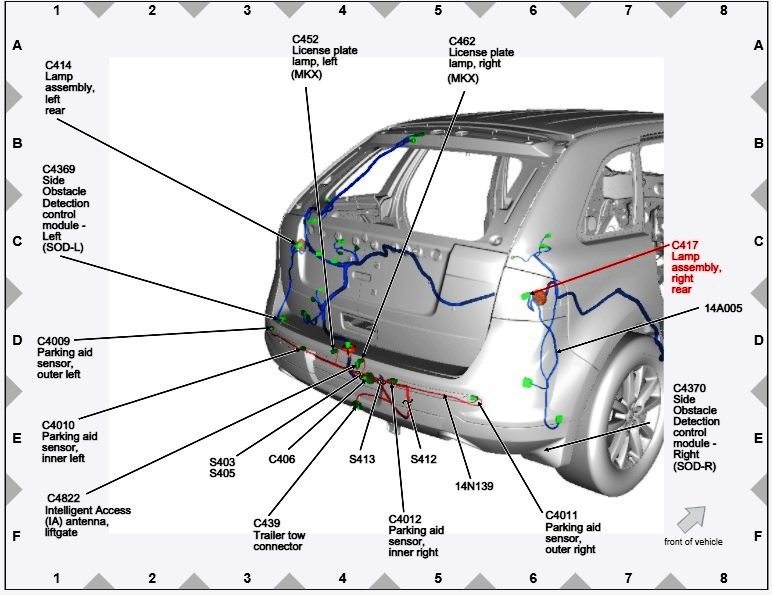
To assist you toward resolution of your Edge's right rear turn signal problem, below are PDF download links to Turn Signal and Hazard Lamps Diagnosis and Testing Procedures, and other related sections from the 2014 Edge Workshop Manual, as well as wiring and connector location diagrams as images... Good luck! Turn Signal and Hazard Lamps Diagnosis and Testing Procedures - 2014 Edge Workshop Manual.pdf Right Rear Stop-Tail Light Connector C417 - Wiring-Circuit Legend - 2014 Edge Workshop Manual.pdf Body Control Module (BCM) Connector C2280C Wiring-Circuit Legend - 2014 Edge Workshop Manual.pdf Instrument Panel - Exploded View - 2014 Edge Workshop Manual.pdf Body Control Module (BCM) Removal and Installation - 2014 Edge Workshop Manual.pdf Module Configuration Includes BCM - 2014 Edge Workshop Manual.pdf Body Control Module (BCM) - Principles of Operation The Body Control Module (BCM) controls various systems by monitoring inputs from switches, sensors and messages sent from other modules. The BCM activates outputs based on the inputs received. For example, the Front Lighting Control Module (FLM) monitors the headlamp switch and transmits the headlamp switch position to the BCM over the network. Based on this input, the BCM may provide voltage to the exterior lamps. Field-Effect Transistor (FET) Protection A Field-Effect Transistor (FET) is a type of transistor that, when used with module software, monitors and controls current flow on module outputs. The FET protection strategy prevents module damage in the event of excessive current flow. The BCM utilizes an FET protective circuit strategy for many of its outputs (for example, a headlamp output circuit). Output loads (current level) are monitored for excessive current (typically short circuits) and are shut down (turns off the voltage or ground provided by the module) when a fault event is detected. A short circuit DTC is stored at the fault event and a cumulative counter is started. When the demand for the output is no longer present, the module resets the FET protection to allow the circuit to function. The next time the driver requests a circuit to activate that has been shut down by a previous short (FET protection) and the circuit is still shorted, the FET protection shuts off the circuit again and the cumulative counter advances. When the excessive circuit load occurs often enough, the module shuts down the output until a repair procedure is carried out. Each FET protected circuit has 3 predefined levels of short circuit tolerance based on the harmful effect of each circuit fault on the FET and the ability of the FET to withstand it. A module lifetime level of fault events is established based upon the durability of the FET . If the total tolerance level is determined to be 600 fault events, the 3 predefined levels would be 200, 400 and 600 fault events. When each tolerance level is reached, the short circuit DTC that was stored on the first failure cannot be cleared by the clear the CMDTCs command. The module does not allow this code to be cleared or the circuit restored to normal operation until a successful self-test proves that the fault has been repaired. After the self-test has successfully completed (no on-demand DTCs present), DTC U1000:00 and the associated DTC (the DTC related to the shorted circuit) automatically clears and the circuit function returns. When each level is reached, the DTC associated with the short circuit sets along with DTC U1000:00. These DTCs are cleared using the module on-demand self-test, then the Clear DTC operation on the scan tool (if the on-demand test shows the fault corrected). The module never resets the fault event counter to zero and continues to advance the fault event counter as short circuit fault events occur. If the number of short circuit fault events reach the third level, then DTCs U1000:00 and U3000:49 set along with the associated short circuit DTC . DTC U3000:49 cannot be cleared and the module must be replaced after the repair. Gateway Function The BCM acts as a gateway module by receiving information in one format and transmitting it to other modules using another format. For example, the BCM receives the vehicle speed data from the PCM over the High Speed Controller Area Network (HS-CAN) , converts the data into a Medium Speed Controller Area Network (MS-CAN) message and sends (gateways) the message to other network modules such as the HVAC module and the Audio Front Control Module (ACM) . This enables network communication between modules that do not communicate using the same network (HS-CAN or MS-CAN ).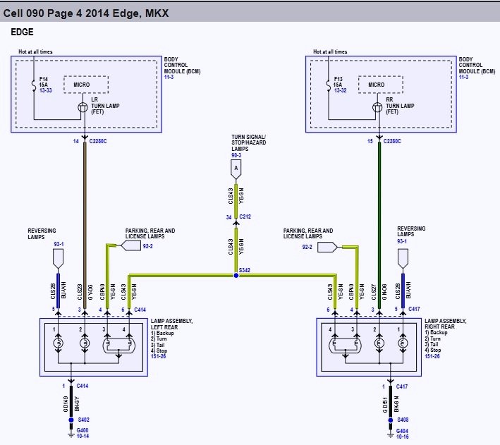
ConnectorC2280CLocationDiagram-2014EdgeWorkshopManual.jpg.c7abdca96ae92be7fae90fed392f6c45.jpg)
-
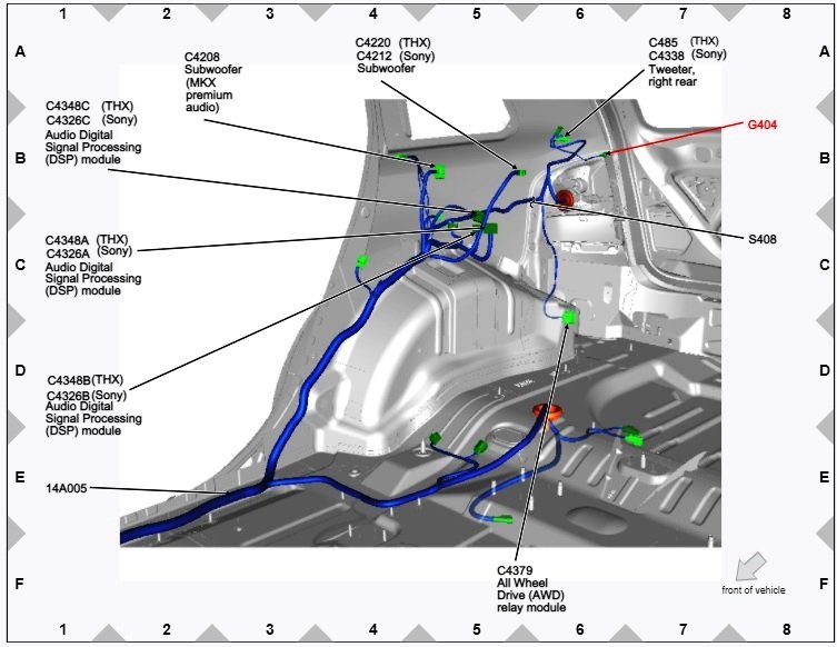
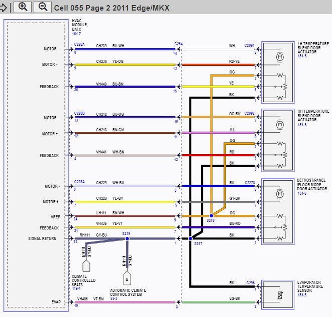
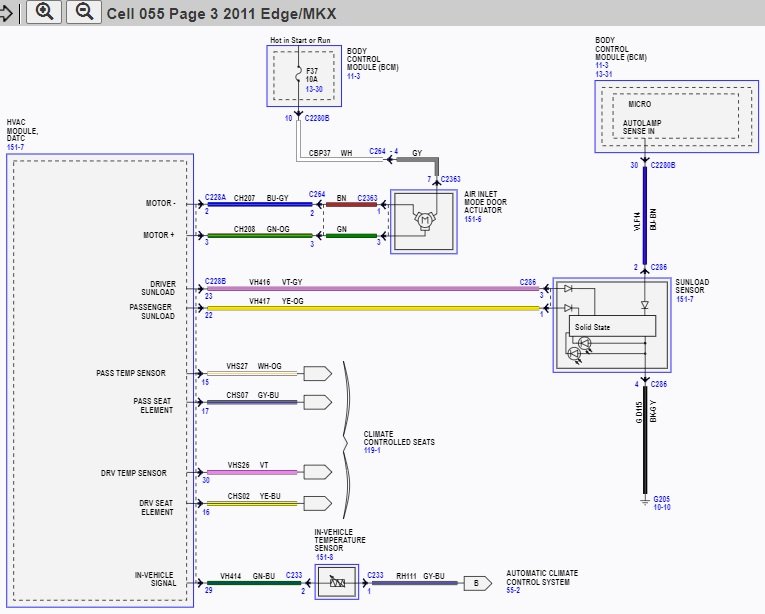
FordeEdge 2011 AC blower turns on and Off
Haz replied to TARiQ's topic in Interior, A.C., Heat, Interior Trim
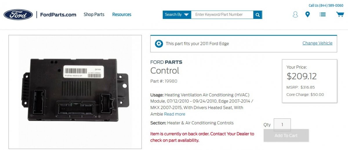
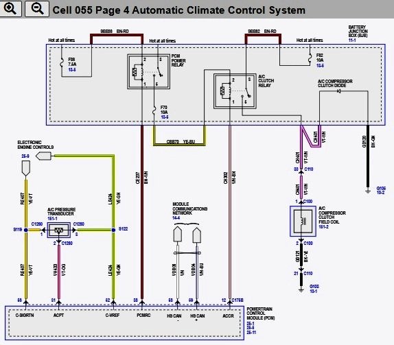
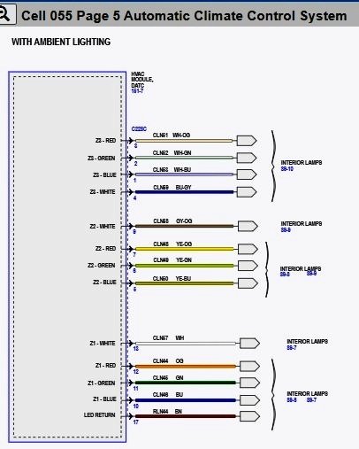
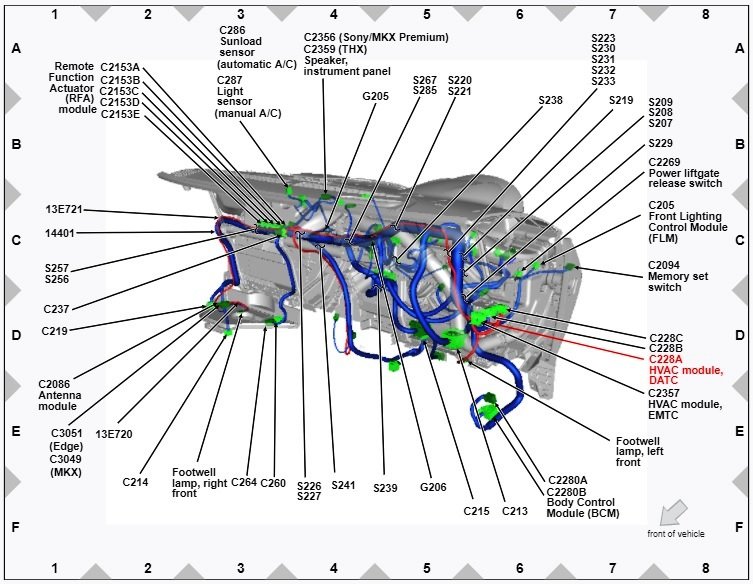
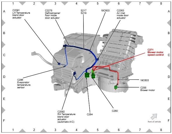
The following Climate Control System descriptions are from the 2011 Edge Workshop Manual... Dual-Zone Electronic Automatic Temperature Control (EATC) The dual-zone Electronic Automatic Temperature Control (EATC) module analyzes input from the following sources: Temperature, airflow mode, blower, A/C and RECIRC selection (made by the vehicle occupants) In-vehicle temperature sensor Ambient temperature sensor Solar radiation sensor (sunload sensor) Evaporator temperature sensor Vehicle speed Engine coolant temperature Using these inputs, the dual-zone HVAC module determines the correct conditions for the following outputs: A/C compressor operation Blower speed Temperature blend door position Airflow mode door position Air inlet door position Control System Inputs The dual-zone EATC system has 4 control system inputs. HVAC Module The EATC system uses a remote HVAC module that is separate from the control interface. The Front Controls Interface Module (FCIM) provides the interface for the vehicle occupants to control the climate control system. When selections are made, the FCIM communicates the selections to the HVAC module through the Medium Speed Controller Area Network (MS-CAN) , and the HVAC module adjusts the climate control system components to achieve the desired state. When the climate control system is operating in AUTO mode via command from the FCIM , the required climate control system settings are determined by the HVAC module. The HVAC module then adjusts the climate control system components to the desired state. The remote HVAC module is located under the driver side of the instrument panel. In-Vehicle Temperature Sensor The in-vehicle temperature sensor contains a thermistor which measures the in-vehicle air temperature and sends that reading to the HVAC module. An aspirator hose is connected between the heater core and evaporator core housing and the in-vehicle temperature sensor. The aspirator hose uses airflow through the heater core and evaporator core housing to create a venturi-type suction to draw in-vehicle air through the in-vehicle temperature sensor (across the thermistor). Solar Radiation Sensor (Sunload Sensor) The solar radiation sensor supplies information to the HVAC module indicating sunload. Ambient Temperature Sensor The ambient temperature sensor signal is received by the PCM and indicates the outside air temperature. The ambient temperature sensor is located in front of the radiator on the radiator support bolster. Control System Outputs The dual-zone EATC system has 4 control system outputs. Blower Motor Speed Control The blower motor speed control controls the blower motor speed by converting low power signals from the HVAC module to a high current, variable ground feed for the blower motor. A delay function provides a gradual increase or decrease in blower motor speed under all conditions. Temperature Blend Door Actuators The dual-zone EATC system uses 2 temperature blend door actuators to control 2 separate temperature blend doors. The temperature blend doors independently vary the LH and RH side temperature settings, as desired. The temperature blend door actuators each contain a reversible electric motor and a potentiometer. The potentiometer circuit consists of a 5-volt reference signal connected to one end of a variable resistor, and a signal ground connected to the other. A signal circuit is connected to a contact wiper, which is driven along the variable resistor by the actuator shaft. The signal to the HVAC module from the contact wiper indicates the position of the temperature blend door. The HVAC module drives the actuator motor in whichever direction is necessary to make the actuator contact wiper voltage agree with the expected HVAC module contact wiper voltage value. Airflow Mode Door Actuator The airflow mode door actuator uses a cam and lever assembly to position the airflow mode doors on command from the HVAC module. The airflow mode door actuator contains a reversible electric motor and potentiometer. The potentiometer allows the HVAC module to monitor the position of the airflow mode doors. The potentiometer circuit consists of a 5-volt reference signal connected to one end of a variable resistor, and a signal ground connected to the other. A signal circuit is connected to a contact wiper, which is driven along the variable resistor by the actuator shaft. The signal to the HVAC module from the contact wiper indicates the position of the airflow mode doors. Air Inlet Mode Door Actuator The air inlet mode door actuator moves the air inlet door between the fresh and RECIRC positions on command from the HVAC module. The air inlet mode door actuator is driven to, and automatically stops at, the full RECIRC or full fresh air inlet position and does not require a potentiometer circuit to monitor its position. Climate Control System Network Communication The controls for the climate control system are in one or more locations depending on vehicle option content. Front Controls Interface Module (FCIM) Instrument Panel Cluster (IPC) (if equipped with steering wheel controls, Dual Automatic Temperature Control (DATC) only) Front Display Interface Module (FDIM) (if equipped with touchscreen controls, DATC only) For DATC systems equipped with touchscreen or steering wheel controls, when the FDIM touchscreen or IPC steering wheel controls are used, they send a function request message over the Infotainment Controller Area Network (I-CAN) to the FCIM . The FCIM reads the climate control selections and sends the requests to the HVAC module in the following message path: The FCIM sends the requests over the I-CAN to the IPC module. The IPC module then relays the requests to Body Control Module (BCM) over the High Speed Controller Area Network (HS-CAN) . Lastly, the BCM then sends the requests to the HVAC module over the Medium Speed Controller Area Network (MS-CAN) . For Electronic Manual Temperature Control (EMTC) systems, the messaging path is followed in reverse for any status updates that need to be sent from the HVAC module to the FCIM and Front Control/Display Interface Module (FCDIM) . For DATC systems, the messaging path is followed in reverse for any status updates that need to be sent from the HVAC module to the FCIM , FCDIM (non-touchscreen), FDIM (touchscreen) and IPC message center. Climate Control System Logic Blower Motor Speed When blower speed is selected, the FCIM sends the desired blower speed to the HVAC module using the message path described above. The HVAC module then commands the blower motor speed control to the desired speed. The HVAC module monitors the blower motor speed control feedback circuit to make sure the blower motor is at the desired speed. Airflow Mode Selection When an airflow mode is selected, the FCIM determines the applicable and allowable airflow direction. The FCIM then sends this desired airflow direction to the HVAC module using the message path described above. The HVAC module determines the actuator position that is required to deliver the correct airflow direction. While monitoring the defrost/panel/floor feedback circuit, the HVAC module drives the actuator until the feedback circuit indicates the actuator has reached its required position. Temperature Selection When a temperature is selected, the FCIM sends the desired temperature selection to the HVAC module using the message path described above. The HVAC module then determines the temperature blend door desired position. While monitoring the temperature blend door feedback circuit, the HVAC module drives the actuator until the feedback circuit indicates the actuator has reached its desired position. Air Inlet Selection When fresh air or RECIRC mode is selected, the FCIM sends the desired selection to the HVAC module using the message path described above. The HVAC module drives the air inlet mode door actuator until the HVAC module detects the actuator reached its end of travel. A spike in current draw tells the HVAC module the actuator has reached the end of its travel. A/C Selection When A/C is selected, the FCIM sends the selection to the HVAC module using the message path described above. If the ambient temperature is sufficient, the HVAC module then sends the request to the BCM over the MS-CAN . The BCM then sends the request to the PCM over the HS-CAN . Field-Effect Transistor (FET) Protection A Field-Effect Transistor (FET) is a type of transistor that, when used with module software, monitors and controls current flow on module outputs. The FET protection strategy prevents module damage in the event of excessive current flow. The HVAC module utilizes an FET protective circuit strategy for its actuator outputs. Output load (current level) is monitored for excessive current (typically short circuits) and is shut down (turns off the voltage or ground provided by the module) when a fault event is detected. A short circuit DTC is stored at the fault event and a cumulative counter is started. When the demand for the output is no longer present, the module resets the FET circuit protection to allow the circuit to function. The next time the driver requests a circuit to activate that has been shut down by a previous short (FET protection) and the circuit is still shorted, the FET protection shuts off the circuit again and the cumulative counter advances. When the excessive circuit load occurs often enough, the module shuts down the output until a repair procedure is carried out. The FET protected circuit has 3 predefined levels of short circuit tolerance based on the harmful effect of each circuit fault on the FET and the ability of the FET to withstand it. A module lifetime level of fault events is established based upon the durability of the FET . If the total tolerance level is determined to be 600 fault events, the 3 predefined levels would be 200, 400 and 600 fault events. When each tolerance level is reached, the short circuit DTC that was stored on the first failure cannot be cleared by a command to clear the DTCs. The module does not allow the DTC to be cleared or the circuit to be restored to normal operation until a successful self-test proves the fault has been repaired. After the self-test has successfully completed (no on-demand DTCs present), DTC U1000:00 and the associated DTC (the DTC related to the shorted circuit) automatically clears and the circuit function returns. When each level is reached, the DTC associated with the short circuit sets along with DTC U1000:00. These DTCs can be cleared using the module self-test, then the Clear DTC operation on the scan tool. The module never resets the fault event counter to zero and continues to advance the fault event counter as short circuit fault events occur. If the number of short circuit fault events reach the third level, then DTCs U1000:00 and U3000:49 set along with the associated short circuit DTC. DTC U3000:49 cannot be cleared and a new module must be installed after the repair. The following are HVAC Module DTCs, which are indicative of the vehicle functions the HVAC Module influences, also from the 2011 Edge Workshop Manual... HVAC Module DTC Chart NOTE: This module utilizes a 5-character DTC followed by a 2-character failure-type code. The failure-type code provides information about specific fault conditions such as opens or shorts to ground. Continuous Memory Diagnostic Trouble Codes (CMDTCs) have an additional 2-character DTC status code suffix to assist in determining DTC history. NOTE: Network DTCs (U-codes) are often a result of intermittent concerns such as damaged wiring or low battery voltage occurrences. Additionally, vehicle repair procedures such as module reprogramming often set network DTCs. Replacing a module to resolve a network DTC is unlikely to resolve the concern. To prevent repeat network DTC concerns, inspect all network wiring, especially connectors. Test the vehicle battery, refer to Section 414-01. DTC Description Action to Take B1034:11 Left Front Seat Heater Element: Circuit Short to Ground REFER to Section 501-10. B1034:13 Left Front Seat Heater Element: Circuit Open REFER to Section 501-10. B1036:11 Right Front Seat Heater Element: Circuit Short to Ground REFER to Section 501-10. B1036:13 Right Front Seat Heater Element: Circuit Open REFER to Section 501-10. B1038:11 Left Front Seat Heater Sensor: Circuit Short to Ground REFER to Section 501-10. B1038:12 Left Front Seat Heater Sensor: Circuit Short to Battery REFER to Section 501-10. B103A:11 Right Front Seat Heater Sensor: Circuit Short to Ground REFER to Section 501-10. B103A:12 Right Front Seat Heater Sensor: Circuit Short to Battery REFER to Section 501-10. B1081:07 Left Temperature Damper Motor: Mechanical Failure GO to Pinpoint Test O. B1081:11 Left Temperature Damper Motor: Circuit Short to Ground GO to Pinpoint Test O. B1081:12 Left Temperature Damper Motor: Circuit Short to Battery GO to Pinpoint Test O. B1081:13 Left Temperature Damper Motor: Circuit Open GO to Pinpoint Test O. B1082:07 Right Temperature Damper Motor: Mechanical Failure GO to Pinpoint Test P. B1082:11 Right Temperature Damper Motor: Circuit Short to Ground GO to Pinpoint Test P. B1082:12 Right Temperature Damper Motor: Circuit Short to Battery GO to Pinpoint Test P. B1082:13 Right Temperature Damper Motor: Circuit open GO to Pinpoint Test P. B1086:07 Air Distribution Damper Motor: Mechanical Failure GO to Pinpoint Test J. B1086:11 Air Distribution Damper Motor: Circuit Short to Ground GO to Pinpoint Test J. B1086:12 Air Distribution Damper Motor: Circuit Short to Battery GO to Pinpoint Test J. B1086:13 Air Distribution Damper Motor: Circuit Open GO to Pinpoint Test J. B10AF:12 Blower Fan Relay: Circuit Short to Battery GO to Pinpoint Test Q. B10AF:13 Blower Fan Relay: Circuit Open GO to Pinpoint Test Q. B10B9:12 Blower Control: Circuit Short to Battery GO to Pinpoint Test R. B10B9:14 Blower Control: Circuit Short to Ground or Open GO to Pinpoint Test Q. B11E5:11 Left HVAC Damper Position Sensor: Circuit Short to Ground GO to Pinpoint Test O. B11E5:15 Left HVAC Damper Position Sensor: Circuit Short to Battery or Open GO to Pinpoint Test O. B11E6:11 Right HVAC Damper Position Sensor: Circuit Short to Ground GO to Pinpoint Test P. B11E6:15 Right HVAC Damper Position Sensor: Circuit Short to Battery or Open GO to Pinpoint Test P. B11E7:11 Air Distribution Damper Position Sensor: Circuit Short to Ground GO to Pinpoint Test J. B11E7:15 Air Distribution Damper Position Sensor: Circuit Short to Battery or Open GO to Pinpoint Test J. B127B:11 Ambient Lighting Zone 1 Output Red LED: Circuit Short to Ground REFER to Section 417-02. B127B:13 Ambient Lighting Zone 1 Output Red LED: Circuit Open REFER to Section 417-02. B127C:11 Ambient Lighting Zone 2 Output Red LED: Circuit Short to Ground REFER to Section 417-02. B127C:13 Ambient Lighting Zone 2 Output Red LED: Circuit Open REFER to Section 417-02. B127D:11 Ambient Lighting Zone 3 Output Red LED: Circuit Short to Ground REFER to Section 417-02. B127D:13 Ambient Lighting Zone 3 Output Red LED: Circuit Open REFER to Section 417-02. B127E:11 Ambient Lighting Zone 1 Output Green LED: Circuit Short to Ground REFER to Section 417-02. B127E:13 Ambient Lighting Zone 1 Output Green LED: Circuit Open REFER to Section 417-02. B127F:11 Ambient Lighting Zone 2 Output Green LED: Circuit Short to Ground REFER to Section 417-02. B127F:13 Ambient Lighting Zone 2 Output Green LED: Circuit Open REFER to Section 417-02. B1280:11 Ambient Lighting Zone 3 Output Green LED: Circuit Short to Ground REFER to Section 417-02. B1280:13 Ambient Lighting Zone 3 Output Green LED: Circuit Open REFER to Section 417-02. B1281:11 Ambient Lighting Zone 1 Output Blue LED: Circuit Short to Ground REFER to Section 417-02. B1281:13 Ambient Lighting Zone 1 Output Blue LED: Circuit Open REFER to Section 417-02. B1282:11 Ambient Lighting Zone 2 Output Blue LED: Circuit Short to Ground REFER to Section 417-02. B1282:12 Ambient Lighting Zone 2 Output Blue LED: Circuit Short to Battery REFER to Section 417-02. B1283:11 Ambient Lighting Zone 3 Output Blue LED: Circuit Short to Ground REFER to Section 417-02. B1283:13 Ambient Lighting Zone 3 Output Blue LED: Circuit Open REFER to Section 417-02. B12F1:11 Ambient Lighting Zone 1 Output : Circuit Short to Ground REFER to Section 417-02. B12F1:13 Ambient Lighting Zone 1 Output : Circuit Open REFER to Section 417-02. B12F2:11 Ambient Lighting Zone 2 Output : Circuit Short to Ground REFER to Section 417-02. B12F2:13 Ambient Lighting Zone 2 Output : Circuit Open REFER to Section 417-02. B1321:11 Ambient Lighting Zone 3 Output: Circuit Short to Ground REFER to Section 417-02. B1321:13 Ambient Lighting Zone 3 Output: Circuit Open REFER to Section 417-02. B1A61:11 Cabin Temperature Sensor: Circuit Short to Ground GO to Pinpoint Test D. B1A61:15 Cabin Temperature Sensor: Circuit Short to Battery or Open If only DTC B1A61:15 is set, GO to Pinpoint Test D. If DTC B1A61:15, B1A63:15 and B1A64:15 all set, GO to Pinpoint Test T. B1A63:11 Right Solar Sensor: Circuit Short to Ground GO to Pinpoint Test E. B1A63:15 Right Solar Sensor: Circuit Short to Battery or Open If only DTC B1A63:15 is set, GO to Pinpoint Test E. If DTC B1A61:15, B1A63:15 and B1A64:15 all set, GO to Pinpoint Test T. B1A64:11 Left Solar Sensor: Circuit Short to Ground GO to Pinpoint Test E. B1A64:15 Left Solar Sensor: Circuit Short to Battery or Open If only DTC B1A64:15 is set, GO to Pinpoint Test E. If DTC B1A61:15, B1A63:15 and B1A64:15 all set, GO to Pinpoint Test T. B1B71:11 Evaporator Temperature Sensor: Circuit Short to Ground GO to Pinpoint Test F. B1B71:15 Evaporator Temperature Sensor: Circuit Short to Battery or Open GO to Pinpoint Test F. B1C83:11 Rear Defog Relay: Circuit Short to Ground REFER to Section 501-11. B1C83:13 Rear Defog Relay: Circuit Open REFER to Section 501-11. C1B14:11 Sensor Supply Voltage A: Circuit Short to Ground GO to Pinpoint Test C. C1B14:12 Sensor Supply Voltage A: Circuit Short to Battery GO to Pinpoint Test C. U0140:00 Lost Communication With Body Control Module: No Sub Type Information GO to Pinpoint Test S. U0401:09 Invalid Data Received From ECM/PCM A: Component Failure This DTC can set due to a fault in the PCM. CARRY OUT a self-test of the PCM and DIAGNOSE any PCM DTCs present, REFER to Section 303-14. U0401:68 Invalid Data Received From ECM/PCM A: Event Information This DTC can set due to a fault in the PCM. CARRY OUT a self-test of the PCM and DIAGNOSE any PCM DTCs present, REFER to Section 303-14. U0401:81 Invalid Data Received From ECM/PCM A: Invalid Serial Data Received This DTC can set due to a fault in the PCM. CARRY OUT a self-test of the PCM and DIAGNOSE any PCM DTCs present, REFER to Section 303-14. U0401:82 Invalid Data Received From ECM/PCM A: Alive/Sequence Counter Incorrect/Not Updates This DTC can set due to a fault in the PCM. CARRY OUT a self-test of the PCM and DIAGNOSE any PCM DTCs present, REFER to Section 303-14. U0422:68 Invalid Data Received From Body Control Module: Event Information This DTC can set due to a fault in the Body Control Module (BCM) . CARRY OUT a self-test of the BCM and DIAGNOSE any BCM DTCs present, REFER to Section 419-10. U0422:81 Invalid Data Received From Body Control Module: Invalid Serial Data Received This DTC can set due to a fault in the Body Control Module (BCM) . CARRY OUT a self-test of the BCM and DIAGNOSE any BCM DTCs present, REFER to Section 419-10. U0423:82 Invalid Data Received From Instrument Panel Cluster Control Module: Alive/Sequence Counter Incorrect/Not Updates This DTC can set due to a fault in the Instrument Panel Cluster (IPC) . CARRY OUT a self-test of the IPC and DIAGNOSE any IPC DTCs present, REFER to Section 413-01. U0554:82 Invalid Data Received From Accessory Protocol Interface Module: Alive/Sequence Counter Incorrect/Not Updates This DTC can set due to a fault in the Accessory Protocol Interface Module (APIM) . CARRY OUT a self-test of the APIM and DIAGNOSE any APIM DTCs present, REFER to Section 415-00. U1000:00 Solid State Driver Protection Activated — Driver Disabled: No Sub Type Information The HVAC module has temporarily disabled an output because an excessive current draw exists (such as a short to ground). The HVAC module cannot enable the output until the cause of the short is corrected. ADDRESS all other DTCs first. After the cause of the concern is corrected, CLEAR the DTCs. REPEAT the self-test. U2024:51 Control Module Cal-Config Data: Not Programmed CARRY OUT Programmable Module Installation (PMI) on the HVAC module. REFER to Section 418-01. REPEAT the self-test. If PMI is successful, the DTC will not be present. If the DTC returns, INSTALL a new HVAC module. REFER to Section 412-01. TEST the system for normal operation. U2100:00 Initial Configuration Not Complete: No Sub Type Information CARRY OUT Programmable Module Installation (PMI) on the HVAC module. REFER to Section 418-01. REPEAT the self-test. If PMI is successful, the DTC will not be present. If the DTC returns, INSTALL a new HVAC module. REFER to Section 412-01. TEST the system for normal operation. U3000:41 Control Module: General Checksum Failure INSTALL a new HVAC module. REFER to Section 412-01. TEST the system for normal operation. U3000:49 Control Module: Internal Electronic Failure The module has permanently disabled an output because an excessive current draw fault (such as a short to ground) has exceeded the limits that the HVAC module can withstand. The cause of the excessive current draw MUST be corrected before a new HVAC module is installed. ADDRESS all other DTCs first. After the cause of the concern is corrected, INSTALL a new HVAC module. REFER to Section 412-01. TEST the system for normal operation. U3002:62 Vehicle Identification Number: Signal Compare Failure CARRY OUT Programmable Module Installation (PMI) on the HVAC module. REFER to Section 418-01. REPEAT the self-test. If PMI is successful, the DTC will not be present. If the DTC returns, INSTALL a new HVAC module. REFER to Section 412-01. TEST the system for normal operation. U3003:16 Battery Voltage: Circuit Voltage Below Threshold GO to Pinpoint Test G. U3003:17 Battery Voltage: Circuit Voltage Above Threshold GO to Pinpoint Test G. So. while various DTCs refer to specific Pinpoint diagnostic routines, the symptom of Blower Motor Does Not Operate Correctly indicates Pinpoint Test R, for which PDF download links of the diagnostic procedure and associated Workshop Manual selections are included below, along with images of wiring diagrams, connector location diagrams, and a FordParts online listing for the HVAC Module part # 19980. Good luck! Pinpoint Test R - The Blower Motor Does Not Operate Correctly - 2011 Edge Workshop Manual.pdf HVAC Module Connector C228A Wiring-Circuit Legend - 2011 Edge Workshop Manual.pdf Blower Motor Speed Control Connector C271 Wiring-Circuit Legend - 2011 Edge Workshop Manual.pdf Instrument Panel Exploded View - 2011 Edge Workshop Manual.pdf Blower Motor Speed Control Removal and Installation - 2011 Edge Workshop Manual.pdf HVAC Module Removal and Installation - 2011 Edge Workshop Manual.pdf Module Configuration Parameters Includes HVAC Module - 2011 Edge Workshop Manual.pdf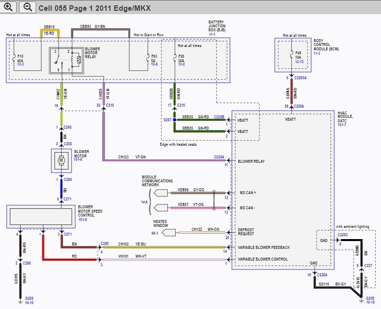

-
Just in case you are not familiar with the Timing Adjustment Procedure, below are PDF download links to this procedure and all its supplemental documents, from the 2011 Edge Workshop Manual... Good luck! Roof Opening Panel General Procedures - Timing Adjustment - 2011 Edge Workshop Manual.pdf Roof Opening Panel Removal and Installation - Front Sliding - 2011 Edge Workshop Manual.pdf Roof Opening Panel Motor - Front Sliding Panel - Removal and Installation - 2011 Edge Workshop Manual.pdf Roof Opening Panel Motor - Shade - 2011 Edge Workshop Manual.pdf Roof Opening Panel Motor Initialization - 2011 Edge Workshop Manual.pdf
-
Heated/cooled seat stopped working 2016 Edge sport B272C
Haz replied to 68lemans462's topic in 2016 Edge & MKX
The following description is from the 2016 Edge Workshop Manual, edited to provide specifics on climate controlled seats, followed by an explanation of the DTC your Edge is exhibiting... Climate Controlled Seats This system allows on-demand, independent, electrical heating/cooling of each front seat. The climate controlled seat system consists of the following components: Blower motor, located within each front seat cushion and backrest Air filter, integrated to each blower motor assembly (not serviceable) Climate-controlled seat buttons, located on the FDIM (touchscreen) FCIM SCME , mounted to the bottom of the front passenger seat Cushion and backrest manifolds Cushion and backrest foam pads Cushion and backrest trim covers Climate Controlled Seat Operation The driver and passenger climate controlled seat buttons are selected from the FCIM and FDIM (touchscreen). The climate controlled seat system functions independently from the vehicle's climate control system. The seat cushion and backrest are each equipped with a blower motor assembly. As cabin air is drawn through each blower motor, a Thermo-Electric Device (TED) heats or cools the air, which is then directed into the foam pad where it is distributed along the surface of the cushion and backrest of the seat. Once the system is activated, the SCME uses a set of flexible algorithms to control the heating/cooling modes and the blower speed dependant on the commanded climate controlled seat settings. The SCME monitors seat cushion temperature while it supplies voltage and ground to both blower motors. The SCME also supplies a variable voltage signal to control the blower speed. Cabin air enters the blower through an integrated filter attached to the blower motor housing. Heated or cooled air exits the blower motor and flows through the foam pad. Climate Controlled Seat Cooling Characteristics In cool mode, the blower motors can remove up to 8° C (14° F) from the ambient air temperature entering the system. The system control settings are based on the 3 indicators next to each climate controlled seat cool switch button on the touchscreen. The first setting is HIGH (3 indicators), the second setting is MED (2 indicators) and the third is LOW (1 indicator) then OFF (no indicators). When cooling, the SCME maintains a constant blower motor speed and a constant Thermo-Electric Device (TED) supply voltage (duty cycle is determined by the switch setting) in COOL mode. Climate Controlled Seat Cooling Characteristics In cool mode, the blower motors can remove up to 8° C (14° F) from the ambient air temperature entering the system. The system control settings are based on the 3 indicators next to each climate controlled seat cool switch button on the touchscreen. The first setting is HIGH (3 indicators), the second setting is MED (2 indicators) and the third is LOW (1 indicator) then OFF (no indicators). When cooling, the SCME maintains a constant blower motor speed and a constant Thermo-Electric Device (TED) supply voltage (duty cycle is determined by the switch setting) in COOL mode. Climate Controlled Seat Recovery Mode NOTE: The presence of overtemperature faults (Diagnostic Trouble Codes (DTCs) B2729, B2730, B272A and B272B) can be induced by incorrectly operating the climate controlled seat system after an initial heat setting has been attained. If a heat setting is repeatedly turned off and on in an attempt to increase the seat temperature or repeatedly toggled between heat and cool modes, an overtemperature condition can result and the Diagnostic Trouble Codes (DTCs) may be set. If the temperature of one of the blower motors rises above 110° C (229.8° F) in the heat mode or 65° C (148.9° F) in the cool mode for more than 4 seconds, the SCME records an overtemperature DTC , removes voltage from the Thermo-Electric Devices (TEDs) (part of the blower motor assembly) and goes into recovery mode (blower only) for 30 seconds to cool down the blower motor. The same occurs if a temperature difference of 60° C (108° F) or greater is detected between the backrest and cushion blower motors on either front seat. The SCME continues to monitor the blower motors while in recovery mode. If the temperature of the Thermo-Electric Devices (TEDs) do not drop to 105° C (220.8° F) in the heat mode or 60° C (139.9° F) in the cool mode after 30 seconds, the system continues to cool the blower motors in recovery mode for up to 5 minutes. If the Thermo-Electric Devices (TEDs) cool down after 30 seconds, but before 5 minutes (checked at 4 second intervals), the system is operating normally. An overtemperature DTC is still recorded even if the system recovers and is operating normally. This is more likely to occur during extreme cabin temperatures with significant seat back sun load. If the system does not recover within 30 seconds in heat mode or within 5 minutes in cool mode, the SCME disables that seat (fault mode) and remains off until the ignition is cycled. Also, if the SCME detects a temperature differential fault twice during the same ignition cycle, the SCME disables the seat. When a fault causes a shutdown, the climate controlled seat indicators turn off and that seat is not operational until the next ignition cycle. Component Description FDIM The FDIM (touchscreen) contains the heated seat (or climate controlled seat) buttons. FCIM The FCIM contains the heated seat (or climate controlled seat) buttons. If equipped with heated seats, the FCIM monitors the seat cushion temperature sensor and supplies heater current to the seat cushion and backrest heater mats until the desired setpoint temperature is reached. Once the setpoint temperature is reached, the FCIM cycles the heater circuits on/off as required to maintain the setpoint temperature. PMI is required when a new FCIM is installed. Heater Mat If equipped with heated seats, the cushion heater mats are each equipped with a temperature sensor (thermistor) which provides feedback to the FCIM . The cushion and backrest heater mats are connected in series. SCME If equipped with climate controlled seats, the SCME controls the operation of the climate controlled seat system. PMI is required when a new SCME is installed. Blower Motor If equipped with climate controlled seats, the seat cushion and backrest are each equipped with a blower motor assembly (Thermo-Electric Device (TED) and fan motor, serviced as an assembly). There is also a temperature sensor (thermistor) in each blower motor which provides feedback to the SCME . The blower motor assembly is controlled by the SCME . +++++++++ DTC B272C Normal Operation and Fault Conditions The SCME is supplied voltage at all times, but the climate controlled seat system only operates with the engine running. The system can be operated with the ignition ON engine OFF by using a scan tool to bypass the climate controlled seat buttons on the touchscreen interface. When commanding a heat or cool mode operation in this manner, the climate controlled seat system only operates in 15 second intervals. Both voltage supply circuits are spliced together internal to the SCME , so if one circuit becomes open, both seats can still be operated. However, if a fault occurs setting a DTC specific to either climate controlled seat, only the affected seat is disabled by the SCME . Cabin air is drawn through and distributed to each of the blower motors located in the seat cushion and backrest. The blower motors then heat or cool the air. The air is then directed into the foam pad where it is distributed along the surface of the cushion and backrest of the seat. Once the system is activated, the SCME uses a set of flexible algorithms to control the heating/cooling modes and the blower speed dependent on the commanded climate controlled seat settings. A differential fault occurs when the cushion and backrest blower motors on an affected seat are reporting very different temperatures to the SCME . This may result from an airflow restriction or a circuit fault of either blower motor area. If a blower motor is clear of obstruction and is operational, check the other blower motor and circuitry on the seat. It is important to note that a blower motor with a higher temperature may be operating correctly and not the area of concern. The other blower motor may be indicating a much lower temperature, causing the DTC to set. DTC Fault Trigger Conditions DTC Description Fault Trigger Conditions B272C Driver Differential Temperature Fault If there is a temperature differential between the driver backrest and cushion blower motor of 60° C (108° F) or more for more than 4 seconds, the blower motor is disconnected or the duct is blocked, this DTC sets. When this happens the first time in a key cycle, the SCME puts the driver seat system into recovery mode (see principles of operation). If the system is able to recover, it functions normally. If the system is able to recover and it occurs a second time in the same key cycle, the SCME shuts down the driver seat system. Possible Causes Wiring, terminals or connectors Restricted backrest blower motor filter Crushed or restricted backrest foam pad Cushion or backrest blower motor SCME ++++++++++ You may want to use Forscan to perform a self-test of the SCME module, to see if the driver's seat climate control function is restored, or if any different DTCs are set. Good luck! -
From the 2008 Edge Workshop Manual, the written Initialization procedure... Good luck! Roof Opening Panel Motor Initialization WARNING: Keep objects and body parts clear of the glass panel when carrying out the initialization procedure. During the initialization procedure, the glass panel closes with high force and cannot detect objects in its path. Failure to follow this instruction may result in serious personal injury. NOTE: New roof opening panel glass motor/shade motors must be initialized after installation. NOTE: An de-initialized glass or shade motor will stutter step open when their respective open switches are pressed. NOTE: The glass close switch must be held during the entire initialization process or the sequence will be aborted and the roof will remain in a de-initialized state. Start the engine. Press and hold the glass close switch until the glass is in CLOSED position. Release, repress and hold the glass close switch (for at least 10 seconds). For a new drive assembly, the glass panel will move toward the front hard-stop, stall and then move backward a few millimeters and then forward. For an existing drive assembly, the glass panel will move toward the front hard-stop and stall. The shade panels will move toward their front hard-stops, stall, move back a few millimeters, then forward. After the shade panels have finished moving backward and forward, release the glass close switch. Press and hold the glass close switch. The glass and shades will fully open together. Then, the glass will close first and then the shades will return to the fully CLOSED position. When the shades have stopped moving, release the glass close switch. Initialization is now complete. Verify successful initialization by carrying out one-touch open, one-touch close, one-touch vent (glass) and one-touch open for the shades. If roof opening panel does not operate correctly, repeat Steps 2 through 4.
-
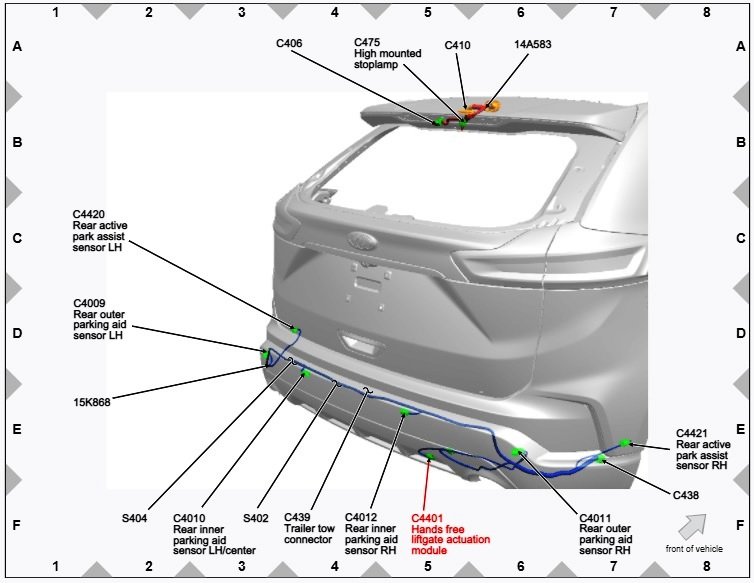
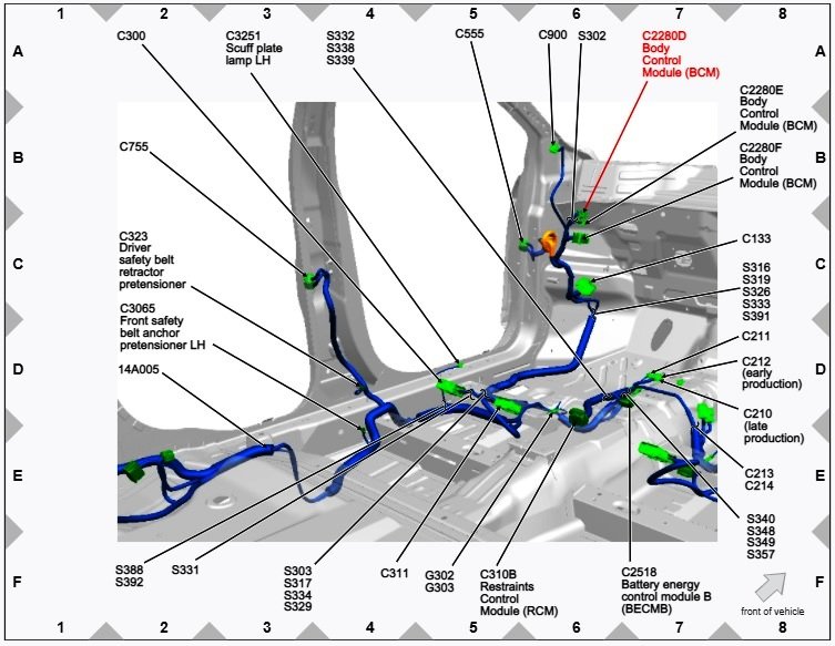
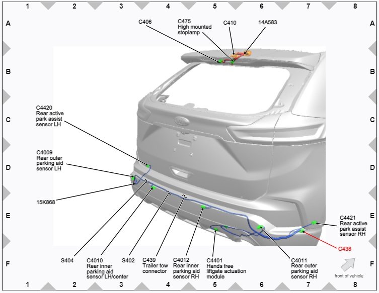
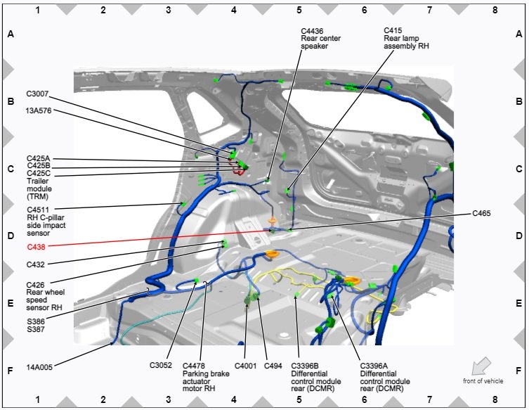
As informational references toward your researching component costs and connector/circuitry availability & requirements, the following are PDF links to related sections from the 2020 Edge Workshop Manual (since you did not mention model year) and connector/component location diagram images. It appears the added Hands Free Liftgate Actuation module with the Upper & Lower sensors deliver an "open sesame" message to the Body Control Module, which then triggers the liftgate to open, similar to using the dash or cargo area switches. Module programming may also be required, perhaps using Forscan, but I am not certain. I am unsure if your local dealership can get authorization to add hands free liftgate actuation, just in case you are not a do-it-yourself owner. It would likely be much more costly to add than the factory-installed option pricing. Good luck! Hands Free Liftgate Actuation Components Description and Location Diagram - 2020 Edge Workshop Manual.pdf Hands-Free Liftgate Actuation Module Removal and Installation - 2020 Edge Workshop Manual.pdf Hands-Free Liftgate Actuation Upper Sensor Removal and Installation - 2020 Edge Workshop Manual.pdf Hands-Free Liftgate Actuation Lower Sensor Removal and Installation - 2020 Edge Workshop Manual.pdf Hands Free Liftgate Wiring Diagram - 2020 Edge Workshop Manual.pdf Connector C4401 Wiring Legend Hands Free Liftgate Actuation Module - 2020 Edge Workshop Manual.pdf Connector C438 Wiring Legend - 2020 Edge Workshop Manual.pdf Connector C2280D Body Control Module Wiring Legend.pdf
-
Body Control Module DTC U0256 Pinpoint P diagnostic routine from 2017 Edge Workshop Manual... Good luck! U0256:87 DTC Fault Trigger Conditions DTC Description Fault Trigger Conditions U0256:87 Lost Communication With Front Controls Interface Module "A" : Missing Message A continuous memory DTC that sets in the BCM if messages from the FCIM through the GWM are missing. Possible Sources Communication network concern Battery voltage concern GWM concern FCIM BCM PINPOINT TEST P: U0256:87 P1 VERIFY THE CUSTOMER CONCERN Ignition ON. Verify there is an observable symptom present. Center Stack Controls Continue To Be Inoperative ? Is an observable symptom present? Yes GO to P2 No The system is operating normally at this time. The DTC may have been set due to high network traffic or an intermittent fault condition. CLEAR the DTC. P2 CHECK THE COMMUNICATION NETWORK Using a diagnostic scan tool, perform a network test. Does the FCIM pass the network test? Yes GO to P3 No DIAGNOSE no communication with the FCIM. REFER to: Communications Network (418-00 Module Communications Network, Diagnosis and Testing). P3 CHECK THE BCM (BODY CONTROL MODULE) CONTINUOUS MEMORY DIAGNOSTIC TROUBLE CODES (CMDTCS) Using a diagnostic scan tool, clear the Diagnostic Trouble Codes (DTCs). Wait 10 seconds. Using a diagnostic scan tool, check the BCM Continuous Memory Diagnostic Trouble Codes (CMDTCs). Is DTC B11D9:16, B11D9:17, U3006:16, U3006:17, U3007:16, U3007:17, U3013:16, U3013:17, U3014:16 or U3014:17 recorded? Yes For DTC B11D9:16, U3006:16, U3007:16, U3013:16 or U3014:16, GO to Pinpoint Test J For DTC B11D9:17, U3006:17, U3007:17, U3013:17 or U3014:17, GO to Pinpoint Test K No GO to P4 P4 RETRIEVE THE DIAGNOSTIC TROUBLE CODES (DTCS) FROM THE FCIM (FRONT CONTROLS INTERFACE MODULE) SELF-TEST Using a diagnostic scan tool, perform the FCIM self-test. Are any Diagnostic Trouble Codes (DTCs) recorded? Yes REFER to: Information and Entertainment System (415-00A Information and Entertainment System - General Information - Vehicles With: AM/FM/CD/SYNC, Diagnosis and Testing). REFER to: Information and Entertainment System (415-00B Information and Entertainment System - General Information - Vehicles With: Touchscreen Display, Diagnosis and Testing). REFER to: Information and Entertainment System (415-00C Information and Entertainment System - General Information - Vehicles With: Sony Audio System, Diagnosis and Testing). No GO to P5 P5 RECHECK THE BCM (BODY CONTROL MODULE) CONTINUOUS MEMORY DIAGNOSTIC TROUBLE CODES (CMDTCS) Using a diagnostic scan tool, clear the Diagnostic Trouble Codes (DTCs). Wait 10 seconds. Using a diagnostic scan tool, check the BCM Continuous Memory Diagnostic Trouble Codes (CMDTCs). Is DTC U0256:87 still present? Yes GO to P6 No The system is operating correctly at this time. The DTC may have been set due to high network traffic or an intermittent fault condition. P6 CHECK FOR DTC (DIAGNOSTIC TROUBLE CODE) U0256 SET IN OTHER MODULES Using a diagnostic scan tool, clear the Diagnostic Trouble Codes (DTCs). Ignition OFF. Ignition ON. Wait 10 seconds. Using a diagnostic scan tool, retrieve all Continuous Memory Diagnostic Trouble Codes (CMDTCs). Is DTC U0256 set in any other module? Yes GO to P7 No GO to P8 P7 CHECK FOR CORRECT FCIM (FRONT CONTROLS INTERFACE MODULE) OPERATION Disconnect and inspect the FCIM connector. Repair: corrosion (install new connector or terminals - clean module pins) damaged or bent pins - install new terminals/pins pushed-out pins - install new pins as necessary Reconnect the FCIM connector. Make sure it seats and latches correctly. Operate the system and determine if the concern is still present. Is the concern still present? Yes CHECK OASIS for any applicable service articles: TSB, GSB, SSM or FSA. If a service article exists for this concern, DISCONTINUE this test and FOLLOW the service article instructions. If no service articles address this concern, VIN required to access Guided Routine (FCIM) No The system is operating correctly at this time. The concern may have been caused by module connections. ADDRESS the root cause of any connector or pin issues. P8 CHECK FOR CORRECT BCM (BODY CONTROL MODULE) OPERATION Disconnect and inspect all BCM connectors. Repair: corrosion (install new connector or terminals - clean module pins) damaged or bent pins - install new terminals/pins pushed-out pins - install new pins as necessary Reconnect the BCM connectors. Make sure they seat and latch correctly. Operate the system and determine if the concern is still present. Is the concern still present? Yes CHECK OASIS for any applicable service articles: TSB, GSB, SSM or FSA. If a service article exists for this concern, DISCONTINUE this test and FOLLOW the service article instructions. If no service articles address this concern, VIN required to access Guided Routine (BCM) No The system is operating correctly at this time. The concern may have been caused by module connections. ADDRESS the root cause of any connector or pin issues.
-
The action of clearing DTCs, and running self-test routines on involved modules afterward, is repeatedly mentioned in the Pinpoint K diagnostic in my prior post, above. It is entirely possible that your Edge's failing/failed battery condition is the root cause of the many DTCs that Forscan revealed. Clearing the DTCs very well may restore the operation of your center-stack controls. Please let us know how it turns out. Good luck!