Haz
-
Posts
1,460 -
Joined
-
Last visited
-
Days Won
392
Content Type
Profiles
Forums
Gallery
Everything posted by Haz
-
Aftermarket hitch and drilling
Haz replied to thesavo's topic in Cargo, Hauling, Roof Racks & Towing
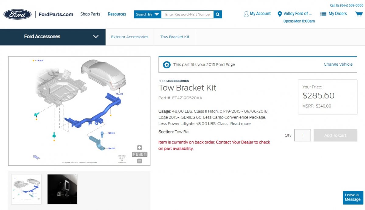
Per the instructions linked below, the fasteners removed from the bumper bar may be retained and reused for the hitch installation... 2015-2018 Edge Factory No-Drill Trailer Hitch Installation Instructions 2.pdf Good luck! -
Park outdoors: Ford expands recall for possible engine fires
Haz replied to 1004ron's topic in Articles, News & Reviews
It is worth noting that Edge, MKX, and Nautilus are not involved in the described headlined Recalls. Good luck! -
From the 2015 Edge Workshop Manual, as PDF download links below... Tire Pressure Monitoring System (TPMS) - System Operation and Component Description - 2015 Edge Workshop Manual.pdf Tire Pressure Monitoring System (TPMS) - Diagnosis and Testing - 2015 Edge Workshop Manual.pdf Tire Pressure Monitoring System (TPMS) - Component Location - 2015 Edge Workshop Manual.pdf The Workshop Manual does not provide diagnostic procedures specific to the Radio Transceiver Module (RTM), but does offer evaluation of the RTM in the context of the involved component -- in this case, within the TPMS diagnostics linked above. If your diagnostic efforts progress to requiring electrical connector details, just let me know and I will provide them. If your efforts progress to the RTM... Radio Transceiver Module (RTM) - Removal and Installation - 2015 Edge Workshop Manual.pdf Headliner Lowering - 2015 Edge Workshop Manual.pdf Good luck!
-
Below is a PDF download link to a job aid on parasitic current draw analysis... Parasitic Battery Drain Job Aid.pdf Good luck!
-
'Notice To Dealers' letter updated; Owner Refunds information added, Sample Letter to Owners added, and Recall Repair Technical Info added. Good luck!
-
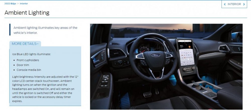
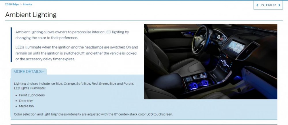
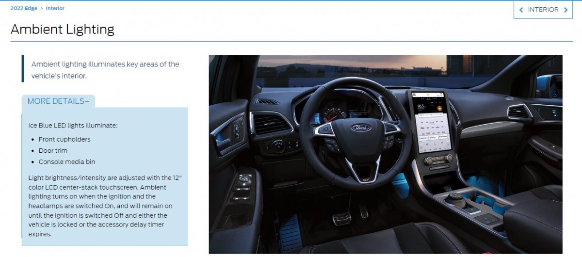
An online resource for dealership sales reps indicates Ice Blue as the only Ambient Light color on 2022 & 2021 Edges... ...and it shows 2020 Edge being the last model year having multi-color Ambient Light selection... According to Helm Inc, Ford has not yet released to them the 2022 Edge Workshop Manual. Hopefully, they are correcting issues like the Ambient Light feature in the 2022 Edge edition, which Helm will eventually market on a CD. Omar302's encouragement to report the unreliable 'On' Ambient Lights setting to your dealership Service department is worthwhile. If they feed the issue's existence back up the chain, through the Technical Assistance Center, a corrective software update could be developed. As an example -- and for any GEN 1+ Edge/MKX owners coming to this discussion with a comparable issue -- below is a PDF download link to TSB 14-0175... TSB 14-0175 - 2011-2014 Edge & MKX - Ambient Lighting Defaults to White or Ice Blue After Cycling Ignition Switch.pdf Good luck!
-
From the 2022 Edge Workshop Manual... Ambient Lighting The ambient lighting subsystem consists of the BCM , and the Light Emitting Diodes (LEDs) located within the floor console, front and rear door panels, instrument panel and front and rear footwell areas. The ambient lighting is operational when the ignition is in any state other than OFF (the exception is when it is used in conjunction with the illuminated entry/exit features), the headlamps are on and the outside ambient light level is low. The BCM provides the voltage to the ambient lighting system, while the touchscreen ( FDIM ) is used to cycle through the different color variations or turn the ambient lighting feature on or off. A LIN circuit is routed from the BCM to all of the Light Emitting Diodes (LEDs). There are 3 Light Emitting Diodes (LEDs) (red, blue and green) housed within each LED assembly. By illuminating various color combinations, the Light Emitting Diodes (LEDs) are able to produce different colors of ambient light. The APIM uses software to monitor the user interface from the touchscreen. Based on the ambient lighting system selections made using the touchscreen, the APIM sends ambient light color request and ambient light intensity request messages over the communication network for color and brightness settings. The BCM retains the last color and brightness setting between uses. I looked for Ambient Lighting TSBs and SSMs, but there are none. Perhaps the next OTA update will correct it. Good luck!
-
Good thought, enigma-2... Good luck!
-
On your 2019 Edge, the roof-mounted sharkfin antenna only provides signals for the GPS and satellite radio functions. Per the 2019 Edge Workshop Manual, with additional relevant sections in PDF download links and images below... GPS /Satellite Radio Antenna The GPS /satellite radio antenna contains a GPS antenna circuit board that receives radio waves containing GPS and satellite radio data (vehicles equipped with a satellite radio). The data is sent through the coaxial cable to the APIM ( GPS data) and through a splitter to the ACM (satellite radio data). Audio Unit Antenna The audio unit antenna (also called the AM / FM 1 antenna) is an on-glass antenna, mounted to the left side of the rear window. It receives AM / FM radio waves and sends them through the audio unit antenna amplifier to the ACM via the audio unit antenna coaxial cable (also called the AM / FM 1 antenna coaxial cable). Audio Unit Antenna Amplifier The audio unit antenna amplifier (also called the AM / FM 1 antenna amplifier) amplifies AM / FM radio signals to improve reception. The amplified signal is sent through a coaxial cable to the ACM . The amplifier is powered by the ACM through the coaxial cable. FM 2 Diversity Antenna The FM 2 diversity antenna is an on-glass antenna, mounted to the right side of the rear window. The FM 2 diversity antenna improves FM reception in urban areas or anywhere large objects reflect FM signals and create multiple FM signal paths. FM 2 Diversity Antenna Amplifier The FM 2 diversity antenna amplifier amplifies FM radio signals and transmits them through a coaxial cable to the ACM . Voltage for the amplifier is provided by the ACM through the coaxial cable. Antenna Inputs Wiring Diagram Pinpoint Test A - Poor AM-FM Reception - Diagnosis and Testing - 2019 Edge Workshop Manual.pdf ACM Antenna Inputs & Amplifier Wiring Diagram - 2019 Edge Workshop Manual.pdf Antenna Isolator Module - Removal and Replacement - 2019 Edge Workshop Manual.pdf AM-FM1 Antenna Amplifier - Removal and Replacement - 2019 Edge Workshop Manual.pdf FM2 Diversity Antenna Amplifier - Removal and Replacement - 2019 Edge Workshop Manual.pdf Audio Unit Antenna Cable Removal and Replacement - 2019 Edge Workshop Manual.pdf Information and Entertainment System - System Operation and Component Description - 2019 Edge Workshop Manual.pdf Audio Front Control Module (ACM) Coaxial Connector C240D AM-FM1 Antenna -2019 Edge Workshop Manual.pdf If you require additional Connector information, please let me know, otherwise... Good luck!
AntennaInputsWiringDiagram-2019EdgeWorkshopManual.thumb.jpg.f4146929884711773f7d35734ddd49a2.jpg)
CoaxialConnectorC240DLocationIllustration-2019EdgeWorkshopManual.jpg.6191f77607d15d28b06821e30d1a90c6.jpg)
-
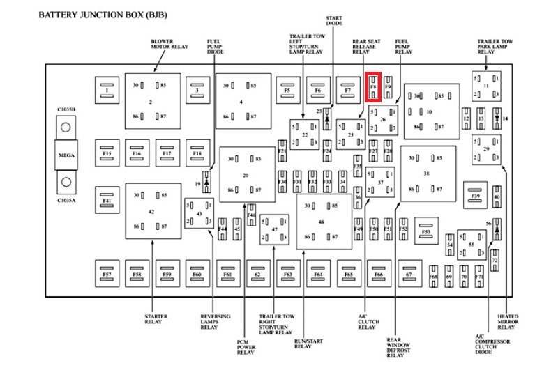
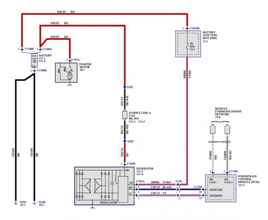
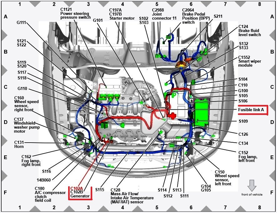
Have you checked fuse F8 in the Battery Junction Box?... Below as PDF download links to relevant sections from the 2008 Edge Workshop Manual Charging System — General Information and Diagnostics - 2008 Edge Workshop Manual.pdf Charging System — Inspection And Verification - 2008 Edge Workshop Manual.pdf Charging System — Diagnostic Trouble Code Chart - 2008 Edge Workshop Manual.pdf Charging System — Diagnostic Pinpoint Test - 2008 Edge Workshop Manual.pdf Charging System Wiring Diagram - 2008 Edge Workshop Manual.pdf Generator Connector C102A Details - 2008 Edge Workshop Manual.pdf Generator Connector C102B Details - 2008 Edge Workshop Manual.pdf Battery Junction Box - Fuse & Relay Locations - 2008 Edge Workshop Manual.pdf Good luck!
-
Aftermarket hitch and drilling
Haz replied to thesavo's topic in Cargo, Hauling, Roof Racks & Towing
Regarding our 2015 MKX, I was fortunate that a prior owner had the factory hitch and Ford Accessories trailer wiring kit installed by the dealer, but it's worth noting that the wiring kit did not enable the trailer tow adjustments to AdvanceTrac and the Distance-To-Empty fuel mileage function. I added the Trailer Sway menu item to the Driver Assist gauge cluster dialogue using Forscan, however it doesn't accept a checkmark to enable functionality. The dealer who installed the cooling system upgrade theorized the Trailer Module would likely be necessary to gain the AdvanceTrac & DTE functions. For my purposes, the gain wasn't worth the additional cost and effort, though the above-linked discussion demonstrates that enthusiastic owner installation of the Trailer Module and required harness is possible. For a more accurate towing DTE calculation, I just reset one of the Trip memories at the beginning of my towing travel and it eventually calculates a useful DTE calculation. Looking at the installation instructions for the Ford wiring kit, which are lengthy, I would be inclined to go with a custom aftermarket semi-plug-and-play harness, just for their simplicity of installation. Good luck! -
Mike: Was the source of the $1,000 repair estimate the Service Department at the dealership where you purchased the Edge new? If so, I expect you voiced comparable displeasure to them about paying for the repair. Did they offer to elevate your case to an Area Factory Service Rep, to see if they could receive a Goodwill authorization from Ford, whereby Ford might cover the cost of the replacement Compressor, if you were willing to pay a percentage, or in-full, for the dealership Labor to install the new Compressor? Did any conversation like that occur, especially if you've bought many of your vehicles there? The terminology would be that you are seeking a Goodwill repair arrangement to ensure your continued customer satisfaction as a long-time Ford & Lincoln owner. Good luck!
-
Hat-tip to WWWPerfA_N0W for standing in the informational gap! PDF download links to 'Pinpoint JD' and its other linked-to references... JD - Crankshaft Position (CKP) Sensor - 2010 FoMoCo Gasoline Powertrain Control Emissions Diagnosis (PC-ED) Manual.pdf Resetting The Keep Alive Memory (KAM) - 2010 FoMoCo Gasoline Powertrain Control Emissions Diagnosis (PC-ED) Manual.pdf Clear the Continuous Diagnostic Trouble Codes (DTCs) and Reset the Emission Monitors Information in the Powertrain Control Module (PCM) - 2010 FoMoCo Gasoline Powertrain Control Emissions Diagnosis (PC-ED) Manual.pdf On Board Diagnostic (OBD) Drive Cycle - 2010 FoMoCo Gasoline Powertrain Control Emissions Diagnosis (PC-ED) Manual.pdf Flash Electrically Erasable Programmable Read Only Memory (EEPROM) - 2010 FoMoCo Gasoline Powertrain Control Emissions Diagnosis (PC-ED) Manual.pdf Good luck!
-
The following is PDF download link for 'No Start Pinpoint Test' from 2010 Gasoline PC/ED Manual... Pinpoint Test For Cranks But Doesn't Start - Fuel or Ignition Issue - 2010 FoMoCo Gasoline Powertrain Control Emissions Diagnosis (PC-ED) Manual.pdf Good luck!
-
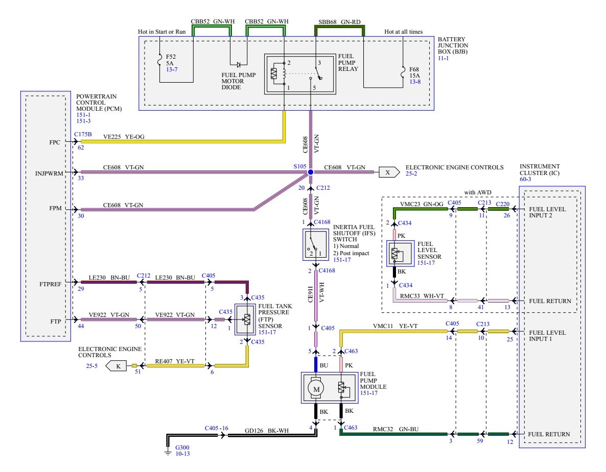
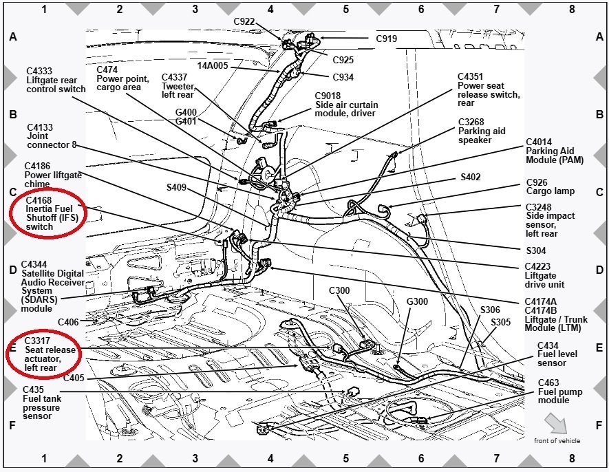
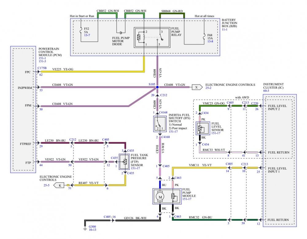
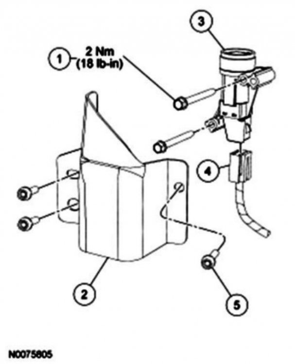
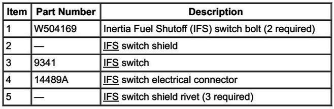
I'm uncertain on interrupted / uninterrupted state of an immovable IFS reset switch. Here is wiring diagram and the IFS switch connector detail. If you've not ruled out IFS involvement, is it possible to verify switch-state by checking across switch's pins 1 & 2, and/or jumper 1 to 2 on harness connector if the switch is determined to be in the interrupted state?
SwitchConnectorC4168Details-2010EdgeWorkshopManual.jpg.67b4a9022c134e4efd5cb738b8fd5fd7.jpg)
-
From the 2010 Edge Workshop Manual.... Fuel System Shutoff Feature The FP module is controlled by the PCM. Electrical power to the FP module is provided through the IFS switch that will de-energize the fuel delivery secondary circuit in the event of a moderate to severe collision. The IFS switch is a safety device, located under the LR quarter trim panel. Should the vehicle shut off after a collision due to this feature, restart the vehicle by first turning the ignition OFF, push the reset button on the IFS switch, then turn the ignition to the ON position. Good luck!
-
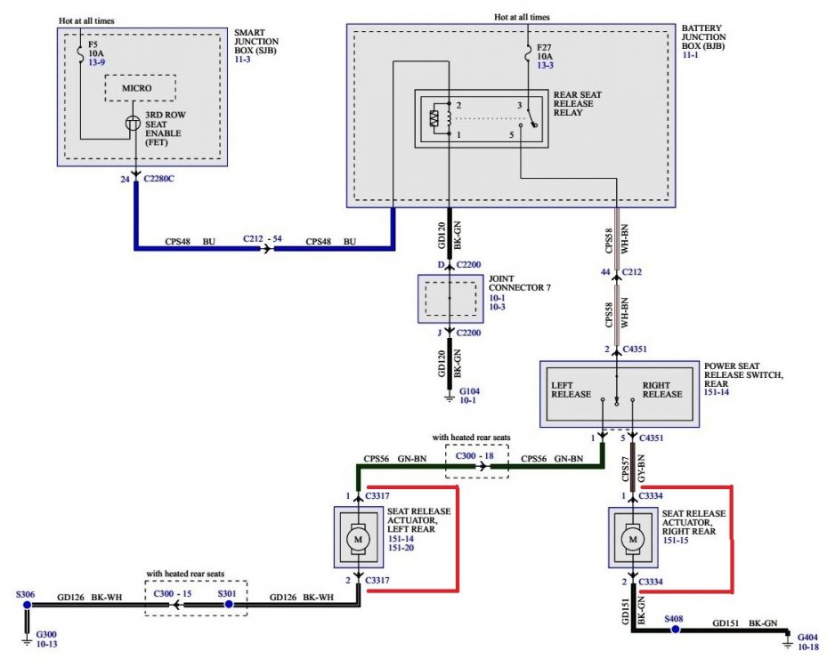
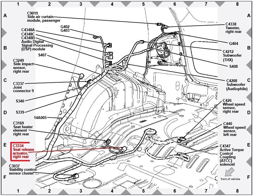
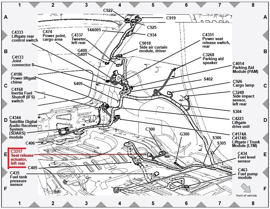
Hopefully by now, you have determined the root cause of your Edge's no-start condition. The connectors in your photos were attached to the left & right Rear Seat Release Actuators that facilitated the remote fold-down of the rear seat backs. Good luck!
-
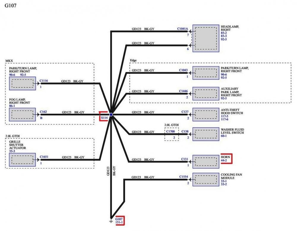
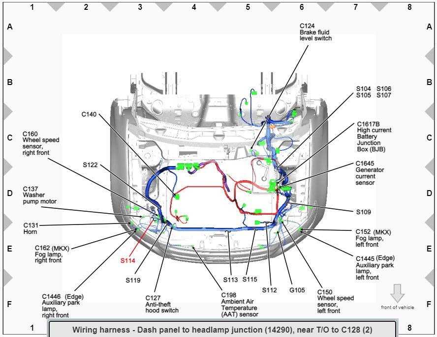
Horn not working 2012 SEL
Haz replied to 12SEL's topic in Alarms, Keyless Entry, Locks & Remote Start
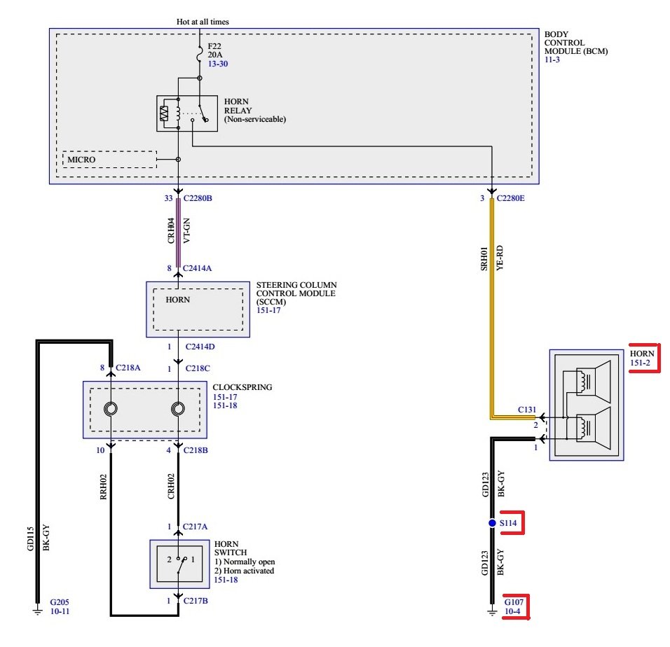
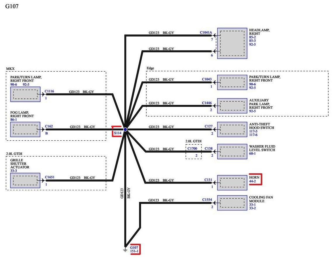
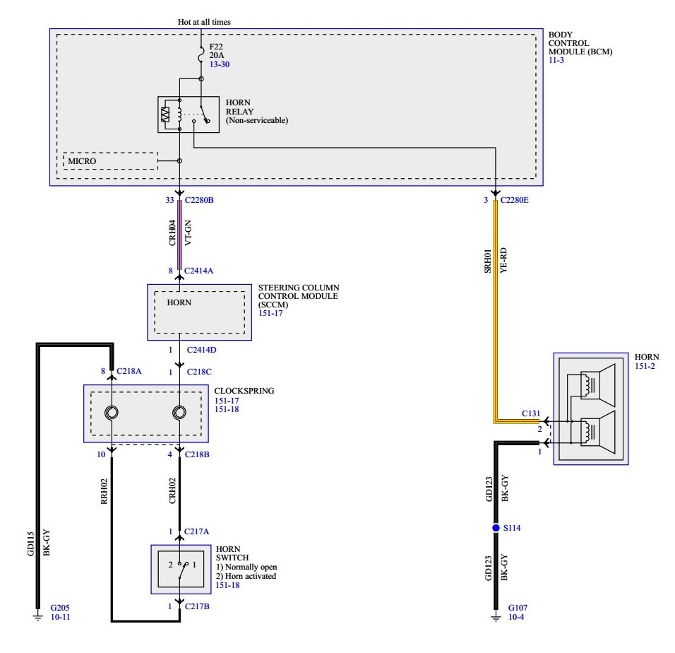
Just in case the aftermarket horn does not solve the problem, here are additional images highlighting the Horn ground circuit, ground wiring termination location, other components utilizing that same ground termination, ground harness location... Good luck!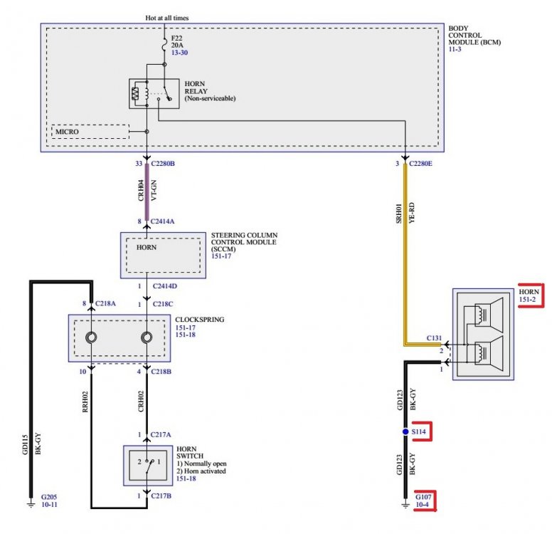

-
@omar302: Is your Sport equipped with HID headlights, and are you running the Forscan DRLs setting, where the turn signal element is lit when HIDs are not on and transmission is not in Park, or, is that not available to GEN 2 owners? This arrangement has been satisfying on our 2012 & 2015 GEN 1+ MKXs, though bulb changes do occur more frequently due to their near-continuous usage. Good luck!
-
Horn not working 2012 SEL
Haz replied to 12SEL's topic in Alarms, Keyless Entry, Locks & Remote Start
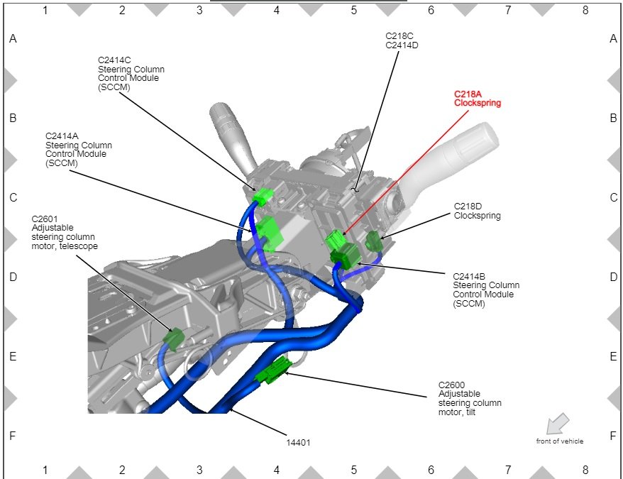
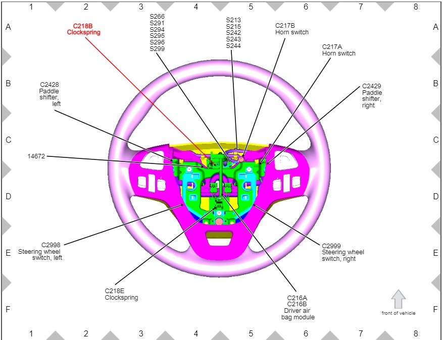
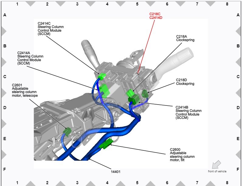
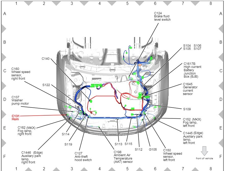
Is this a newly acquired vehicle? Is this a newly occurring problem? Do you have a wiring diagram for the aftermarket remote start to assess if it could be contributing to the problem? Below are PDF download links to relevant sections of the 2012 Edge Workshop Manual, and images, relating to the Edge's horn... Good luck! Horn - Description and Operation - 2012 Edge Workshop Manual.pdf Horn Wiring Diagram - 2012 Edge Workshop Manual.pdf Horn - Diagnosis and Testing - 2012 Edge Workshop Manual.pdf Steering Column Control Module (SCCM) - Connector C2414A - Details - 2012 Edge Workshop Manual.pdf Body Control Module (BCM) - Connector C2280B - Details - 2012 Edge Workshop Manual.pdf Body Control Module (BCM) - Connector C2280E - Details - 2012 Edge Workshop Manual.pdf Clockspring - Connector C218A - Details - 2012 Edge Workshop Manual.pdf Clockspring - Connector C218B - Details - 2012 Edge Workshop Manual.pdf Clockspring - Connector C218C - Details - 2012 Edge Workshop Manual.pdf Horn - Connector C131 - Details - 2012 Edge Workshop Manual.pdf Horn - Removal and Installation - 2012 Edge Workshop Manual.pdf Body Control Module (BCM) - Removal and Installation - 2012 Edge Workshop Manual.pdf Steering Column Shroud - Removal and Installation - 2012 Edge Workshop Manual.pdf Clockspring - Removal and Installation - 2012 Edge Workshop Manual.pdf Steering Column Control Module (SCCM) - Removal and Installation - 2012 Edge Workshop Manual.pdf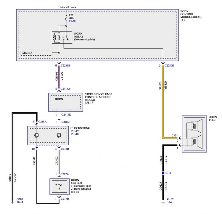
-ConnectorC2414ALocationIllustration-2012EdgeWorkshopManual.jpg.72ae42e5028809f0341413b69231aa00.jpg)
Module-ConnectorC2280BLocationIllustration-2012EdgeWorkshopManual.jpg.12baabaed0c301285b179a72a36f2f36.jpg)
Module-ConnectorC2280ELocationIllustration-2012EdgeWorkshopManual.jpg.f228692d3d35b20c89477cb627609a03.jpg)
-
Aftermarket hitch and drilling
Haz replied to thesavo's topic in Cargo, Hauling, Roof Racks & Towing
These R & I procedures relating to your thrifty hitch install may bolster your DIY confidence... Good luck! Rear Lamp Assembly - Removal and Installation - 2015 Edge Workshop Manual.pdf Rear Bumper Cover - Removal and Installation - 2015 Edge Workshop Manual.pdf Rear Bumper Bar - Removal and Installation - 2015 Edge Workshop Manual.pdf -
Aftermarket hitch and drilling
Haz replied to thesavo's topic in Cargo, Hauling, Roof Racks & Towing
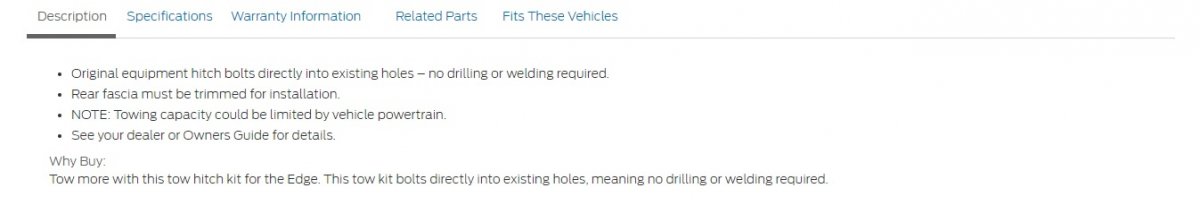
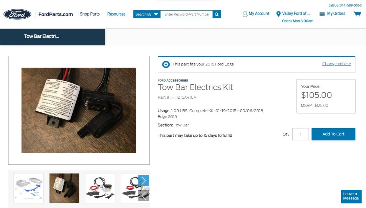
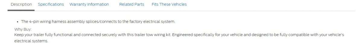
Ford's Accessories Store has listings for a 2015-2018 factory trailer hitch that mounts using existing holes, and also a 4-pin trailer lights wiring kit that splices into existing wiring, which also include an installation cost for each item at your local Ford dealer. Ford's online parts site, FordParts.com, also markets factory Accessories, with pricing that may be lower through your local dealership than the above Ford Accessories Store. Below is a PDF download link to installation instructions for the hitch, to provide you an understanding of what the dealership Service personnel are doing to earn the installation charge, or if you wish to consider installing it yourself... 2015-2018 Edge Factory No-Drill Trailer Hitch Installation Instructions 2.pdf We upgraded our 2015 MKX (GEN 1+) to full tow package specs, described with pricing in this past post. Good luck!


-
Engine wants to stall - Code P1450 & P144A/C - Evap Purge Valve
Haz replied to shumax's topic in 2017-2018 Edge & MKX
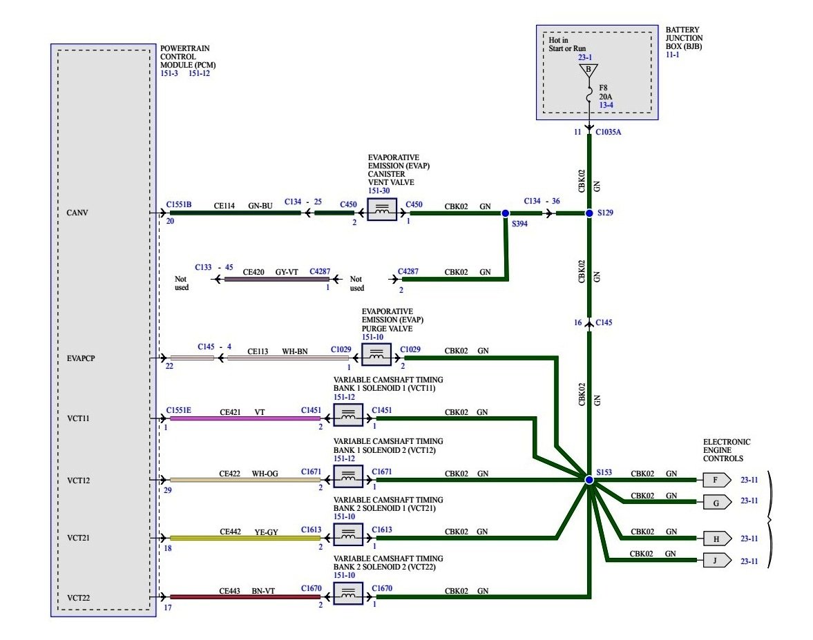
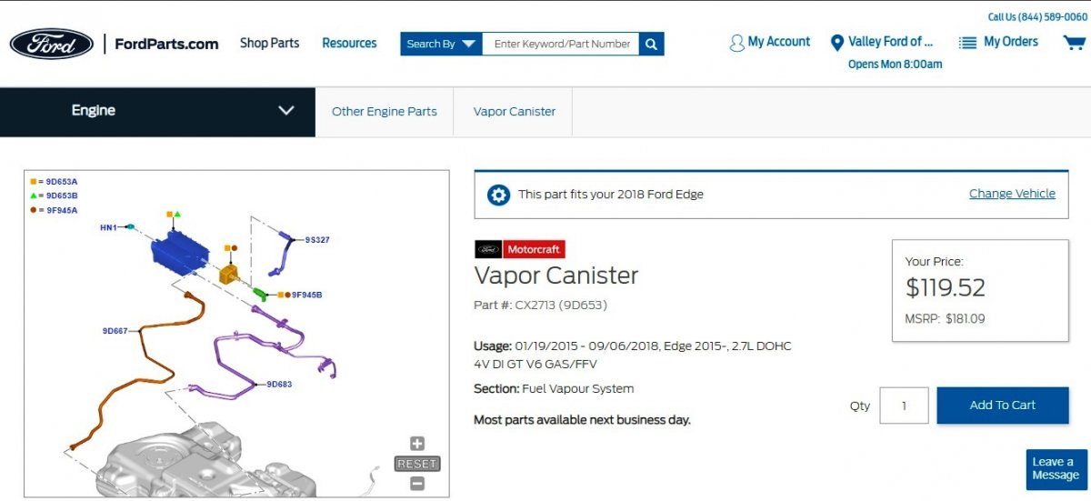
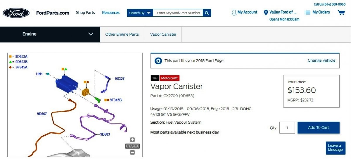
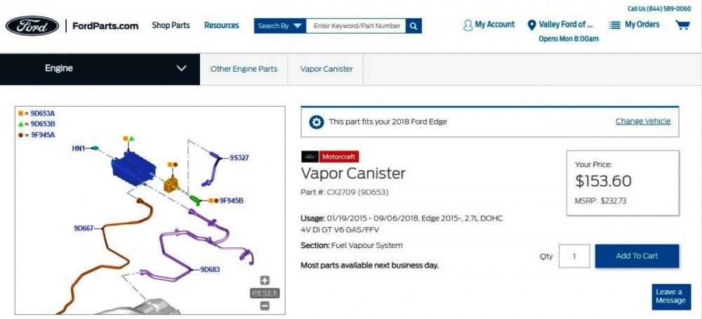
jvuckovic17: Below are relevant sections from 2018 Edge Workshop Manual, and from 2018 Gasoline Powertrain Control- Emission Diagnosis Manual, relating to potential causes of P1450 Diagnostic Trouble Code, Diagnostic Pinpoint Test HX, and other procedures, diagrams, and details, provided as PDF download links and images... Good luck! PINPOINT TEST HX - EVAPORATIVE EMISSION (EVAP) SYSTEM AND MONITOR - 2.7L Ecoboost - 2018 PC-ED Manual.pdf Evaporative Emissions - Overview - 2.7L EcoBoost - 2018 Edge Workshop Manual.pdf Evaporative Emissions - System Operation and Component Description - 2018 Edge Workshop Manual.pdf Evaporative Emission Canister - Removal and Installation - 2.7L EcoBoost - 2018 Edge Workshop Manual.pdf Evaporative Emission Canister Ventilation Filter - Removal and Installation - 2.7L EcoBoost - 2018 Edge Workshop Manual.pdf Evaporative Emission Canister Vent Solenoid - Removal and Installation - 2.7L EcoBoost - 2018 Edge Workshop Manual.pdf Fuel Tank Pressure Sensor and Tube - Removal and Installation - 2.7L EcoBoost - 2018 Edge Workshop Manual.pdf Fuel Tank - Removal and Installation - 2.7L EcoBoost - 2018 Edge.pdf EVAP Components Wiring Diagram - 2.7L EcoBoost - 2018 Edge Workshop Manual.pdf EVAPORATIVE EMISSION (EVAP) CANISTER VENT VALVE - Connector C450 Details - 2018 Edge Workshop Manual.pdf EVAPORATIVE EMISSION (EVAP) PURGE VALVE - Connector C1029 Details - 2018 Edge Workshop Manual.pdf Evaporative Emission Canister Purge Valve - Removal and Installation - 2.7L EcoBoost - 2018 Edge Workshop Manual.pdf Powertrain Control Module (PCM) - Removal and Installation - 2018 Edge Workshop Manual.pdf POWERTRAIN CONTROL MODULE (PCM) Connector C1551B Details - 2018 Edge Workshop Manual.pdf You may input your Edge's VIN into the factory FordParts.com site to determine which Vapor Canister is appropriate for your vehicle, and/or contact them via telephone, or inquire at your local dealership Parts counter, or via your preferred online parts seller ...

CANISTERVENTVALVE-ConnectorC450(UnderBody)LocationIllustration-2018EdgeWorkshopManual.jpg.b1cc8469d4c06e62131124659233f432.jpg)
PURGEVALVE-ConnectorC1029LocationIllustration-2018EdgeWorkshopManual.jpg.5309d7bccf3727d327841d0ae6578ab0.jpg)
ConnectorC1551BLocationIllustration-2018EdgeWorkshopManual.jpg.4cf6acf0ead4491284b7ba40916ca275.jpg)

-
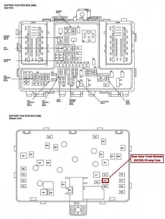
This description of Power Liftgate operation, Open Height Programming, and the Initialization Procedure from the 2021 Edge Workshop Manual may also be helpful... Power Liftgate Power Open The power liftgate power open operation begins when: the RGTM detects the front power liftgate switch is activated. the RGTM detects the rear exterior liftgate release switch is activated. the RGTM receives a message from the BCM (indicating a request from a programmed RKE transmitter or a passive entry feature request). Once the RGTM receives an open request, the power liftgate opens by carrying out the following: The RGTM checks the gear selector lever position and vehicle speed status from the messages received. The RGTM supplies power to the unlatch motor, releasing the liftgate latch The RGTM monitors the liftgate ajar state (the liftgate latch pawl switch opens and both forkbolt switches close to indicate the latch has fully released). When the RGTM detects the power liftgate latch is fully unlatched, it supplies power to the drive motor, opening the power liftgate. While the power liftgate is opening, the RGTM monitors the liftgate motor position sensor for liftgate position and velocity. If an obstruction is detected, the RGTM stops the liftgate drive motor. When the power liftgate reaches the full open position, the RGTM removes the power from the drive motor. If any of the power liftgate switches is activated, a request for the hands-free feature is detected or a double press of the button on a RKE transmitter occurs during a power open, the liftgate stops and holds its position. Power Close The power liftgate power close operation begins when: the RGTM detects the front power liftgate switch is pressed. the RGTM detects the rear interior power liftgate switch is pressed. the RGTM receives a message from the BCM (indicating a double button press from a RKE transmitter or a hands-free request). Once the close request is received, the power liftgate closes by carrying out the following: The RGTM checks the gear selector lever position and vehicle speed status from the messages received. The RGTM starts an audible chime via the audio system. The RGTM supplies power to the drive motor. While the power liftgate is closing, the RGTM monitors the power liftgate motor position sensor (for liftgate position and velocity) and the anti-pinch switches. If an obstruction is detected, the power liftgate stops and reverses. The RGTM monitors the liftgate ajar state. When the RGTM detects the latch has engaged the striker (switches in the latch changing state), power is supplied to the cinching motor to pull the liftgate into the primary latch position and power is removed from the liftgate drive motor. When the RGTM detects the primary latch position has been reached (liftgate is fully closed), the RGTM reverses the direction of the cinching motor until the sector gear switch indicates a start position. If any of the power liftgate switches is activated, a request for the hands-free feature is detected or the button on the RKE transmitter is double pressed during a power close, the liftgate stops and holds its position. Power Liftgate Open Height Programming The power liftgate open height can be programmed to open to a height other than the full open position. To program the power liftgate open height: Open the liftgate. Manually move the liftgate to the desired height. Press and hold the rear power liftgate close switch until a chime is heard, indicating that the new power liftgate maximum open height is successfully programmed. The programmed power liftgate height is retained when the battery is disconnected. NOTE: The power liftgate may not operate correctly under the following conditions: Excessive weight (such as snow or ice) is present on the liftgate. A low voltage or drained battery. A disconnected battery. Repairs/adjustments have been made to the power liftgate strut, the power liftgate motor, the liftgate striker or the liftgate hinges. If any of these conditions have occurred, the power liftgate must be re-initialized. Initialization Disconnect the battery or remove the RGTM fuse [ F76 in Battery Junction Box ] NOTE: Remove the battery power from the RGTM for 20 seconds before entering initialization mode. Wait 20 seconds and reconnect the battery or reinstall the RGTM fuse(s). If the liftgate is not already in the fully closed position, manually close and fully latch the power liftgate. Using a diagnostic scan tool, clear all fault codes for the RGTM . NOTE: If equipped, make sure the power liftgate system is turned ON in the message center before performing this step. NOTE: If the power liftgate does not open during this step, refer to the Symptom Chart to diagnose the inoperative power liftgate. Power open the liftgate by using a programmed RKE transmitter or the front control switch. Once the liftgate is fully open, power close the liftgate by using a programmed RKE transmitter or the front power liftgate control switch. Carry-out the RGTM self-test. If your Edge's warranty coverage still applies, hopefully, this information aids you to better discuss the issue with dealership Service personnel. Good luck!
-
While my source is Ford's secure online website for dealership service technicians, it's public equivalent is marketed through Helm on a CD-ROM for $205 + 7.95 standard shipping with state sales tax collected only for MI, CA, GA & WI addresses. Helm Service Information Manual links: 2017 Edge, 2015 Mustang. This online seller provides an image and listing of information categories contained in the same Ford Service Information Manuals they offer at a price higher than Helm's. Good luck!


AntennaInputsWiringDiagram-2019EdgeWorkshopManual.jpg.2d3471e44d14739240541d74a8a91245.jpg)