Haz
-
Posts
1,468 -
Joined
-
Last visited
-
Days Won
393
Everything posted by Haz
-
Safety Recall 22S43's permanent repair procedure was/is included as PDF download link at bottom of the original post, above, and will also immediately download from here... Safety Recall 22S43 - Technical Info - 07-05-2022.pdf Good luck!
-
Park outdoors: Ford expands recall for possible engine fires
Haz replied to 1004ron's topic in Articles, News & Reviews
1004ron: Your's is a rhetorical question, right? Good luck! -
The following is a relevant diagnostic procedure from the 2015 Edge Workshop Manual without VIN specified, which diminishes guidance... The Outside Air Temperature Display Is Inoperative or Incorrect Normal Operation and Fault Conditions See Outside Air Temperature Display. REFER to: Message Center - System Operation and Component Description (413-01 Instrumentation, Message Center and Warning Chimes, Description and Operation). If the air ambient temperature message is missing or invalid for less than 5 seconds, the IPC defaults the outside air temperature display to the last temperature reading, based upon the last message received. If the air ambient temperature message is missing or invalid for 5 seconds or longer from the PCM , the IPC displays all dashes (- -) in the outside air temperature display area. Possible Sources Communication concern Ambient Air Temperature (AAT) sensor input to the PCM GWM concern FCIM concern PINPOINT TEST AD: THE OUTSIDE AIR TEMPERATURE DISPLAY IS INOPERATIVE OR INCORRECT AD1 PERFORM THE IPC (INSTRUMENT PANEL CLUSTER) SELF-TEST Ignition ON. Using a diagnostic scan tool, perform the IPC self-test. Are any Diagnostic Trouble Codes (DTCs) recorded? Yes REFER to DTC Chart: IPC in this section. No GO to AD2 AD2 PERFORM THE FCIM (FRONT CONTROLS INTERFACE MODULE) SELF-TEST Using a diagnostic scan tool, perform the FCIM module self-test. Are any Diagnostic Trouble Codes (DTCs) recorded? Yes Refer to the appropriate section in Group 415 for the procedure. No GO to AD3 AD3 CHECK THE GWM (GATEWAY MODULE A) DIAGNOSTIC TROUBLE CODES (DTCS) Using a diagnostic scan tool, check the GWM Continuous Memory Diagnostic Trouble Codes (DTCs). Are any Diagnostic Trouble Codes (DTCs) recorded? Yes REFER to: Communications Network (418-00 Module Communications Network, Diagnosis and Testing). No GO to AD4 AD4 PERFORM THE PCM (POWERTRAIN CONTROL MODULE) SELF-TEST Using a diagnostic scan tool, perform the PCM self-test. Are any Diagnostic Trouble Codes (DTCs) recorded? Yes REFER to the appropriate 303-14 section. No GO to AD5 AD5 CHECK THE OUTSIDE AIR TEMPERATURE CONCERN Verify the customer outside air temperature display concern. Is the outside air temperature display concern for an incorrect temperature display? Yes GO to AD6 No VIN required to access Guided Routine (IPC) AD6 CHECK THE AMBIENT AIR TEMPERATURE INPUT TO THE PCM (POWERTRAIN CONTROL MODULE) Using an infrared temperature scanner or similar tool, measure and record the temperature of the ambient air temperature sensor body. Ignition ON. Using a diagnostic scan tool, view the PCM Parameter Identifications (PIDs). Select the ambient air temperature PID (AAT). Monitor the ambient air temperature PID and compare PID value with the recorded temperature of the ambient air temperature sensor body. Does the ambient air temperature PID match the recorded ambient air temperature sensor measurement within +/- 3° C (+/- 5° F)? Yes GO to AD7 No GO to AD8 AD7 CHECK THE OUTSIDE AIR TEMPERATURE DISPLAY UPDATE Drive the vehicle above 33 km/h (20 mph) to allow the outside air temperature display to update. Did the outside air temperature display update toward the actual ambient air temperature? Yes The system is operating correctly at this time. Explain to the customer the operation of the system as it relates to the update strategy. No VIN required to access Guided Routine (FCIM) . AD8 CHECK THE AMBIENT AIR TEMPERATURE SENSOR RESISTANCE Ignition OFF. Disconnect PCM C1381B (2.0L Engine). Disconnect PCM C1551B (2.7L Engine). Disconnect PCM C175B (3.5L Engine). Measure: 2.0L Engine Positive Lead Measurement / Action Negative Lead C1381B-51 C1381B-18 2.7L Engine Positive Lead Measurement / Action Negative Lead C1551B-51 C1551B-18 3.7L Engine Positive Lead Measurement / Action Negative Lead C175B-47 C175B-51 Compare the ambient temperature sensor resistances using the table below. Outside Air Temperature Ambient Air Temperature Sensor Value Celsius Fahrenheit Resistance (K ohms) -1.1° to 4.4° 30° to 40° 27.49 to 33.47 4.4° to 10° 40° to 50° 22.06 to 28.86 10° to 15.6° 50° to 60° 16.63 to 23.10 15.6° to 21.1° 60° to 70° 11.74 to 17.32 21.1° to 26.7° 70° to 80° 9.34 to 12.14 26.7° to 32.2° 80° to 90° 8.49 to 9.62 32.2° to 37.8° 90° to 100° 5.93 to 7.87 37.8° to 43.3° 100° to 110° 4.78 to 6.11 Does the resistance match the table specifications above? Yes GO to AD10 No GO to AD9 AD9 CHECK THE AMBIENT AIR TEMPERATURE SENSOR RESISTANCE Disconnect Ambient Air Temperature Sensor C132 . Measure: Positive Lead Measurement / Action Negative Lead C132-1 Component Side C132-2 Component Side Compare the ambient temperature sensor resistances using the table below. Outside Air Temperature Ambient Air Temperature Sensor Value Celsius Fahrenheit Resistance (K ohms) -1.1° to 4.4° 30° to 40° 27.49 to 33.47 4.4° to 10° 40° to 50° 22.06 to 28.86 10° to 15.6° 50° to 60° 16.63 to 23.10 15.6° to 21.1° 60° to 70° 11.74 to 17.32 21.1° to 26.7° 70° to 80° 9.34 to 12.14 26.7° to 32.2° 80° to 90° 8.49 to 9.62 32.2° to 37.8° 90° to 100° 5.93 to 7.87 37.8° to 43.3° 100° to 110° 4.78 to 6.11 Does the resistance match the table specifications above? Yes The ambient air temperature sensor is operating correctly. REPAIR the circuits for high circuit resistance. No GO to AD11 AD10 CHECK THE AMBIENT AIR TEMPERATURE (AAT) SENSOR FOR OBSTRUCTIONS OR DEBRIS Check the area around the Ambient Air Temperature (AAT) sensor for any obstructions or debris such as leaves or paper. Is the area around the Ambient Air Temperature (AAT) sensor free from any obstructions or debris? Yes GO to AD11 No CLEAR all debris or obstructions as necessary to allow for the free flow of air around the Ambient Air Temperature (AAT) sensor. AD11 CHECK THE AMBIENT AIR TEMPERATURE (AAT) SENSOR OPERATION Disconnect Ambient Air Temperature (AAT) Sensor C132 . Inspect the connector and wiring: water intrusion corrosion damaged pins pushed-out pins Are there any signs of water intrusion, corrosion, damaged or pushed out pins? Yes REPAIR the Ambient Air Temperature (AAT) sensor connector or wiring for any water intrusion, corrosion, damaged or pushed out pins. No INSTALL a new ambient air temperature sensor. With a new Ambient Air Temperature sensor installed, and the Edge's past collision history, it's possible the Body Shop did not recognize and did not repair damage to AAT sensor wiring, since impact occurred in its immediate area. If no relevant Diagnostic Trouble Codes (DTCs) are found, evaluating the new AAT sensor and its wiring using Pinpoint Steps AD8 & AD9 may be helpful. Connector detail documents as PDF download links... POWERTRAIN CONTROL MODULE (PCM) Connector C1381B Details - 2015 Edge Workshop Manual.pdf POWERTRAIN CONTROL MODULE (PCM) Connector C1551B Details - 2015 Edge Workshop Manual.pdf POWERTRAIN CONTROL MODULE (PCM) Connector C175B Details - 2015 Edge Workshop Manual.pdf AMBIENT AIR TEMPERATURE (AAT) SENSOR Connector C132 Details - 2015 Edge Workshop Manual.pdf Good luck!
-
Relevant sections from the 2015 Edge Workshop Manual as PDF download links, below... Evaporative Emission Canister Ventilation Filter Removal and Installation - 2.0L EcoBoost - 2015 Edge Workshop Manual.pdf Evaporative Emission Canister Vent Solenoid Removal and Installation - 2.0L EcoBoost - 2015 Edge Workshop Manual.pdf Evaporative Emission Canister Purge Valve Removal and Installation - 2.0L EcoBoost - 2015 Edge Workshop Manual.pdf Evaporative Emission Canister Removal and Installation - 2.0L EcoBoost - 2015 Edge Workshop Manual.pdf Evaporative Emission Blocking Valve Removal and Installation (if auto Stop-Start Equipped) - 2015 Edge Workshop Manual.pdf Evaporative Emission Canister Components Wiring Diagram - 2015 Edge Workshop Manual.pdf Air Cleaner Outlet Pipe Removal and Installation - 2.0L EcoBoost - 2015 Edge Workshop Manual.pdf Quick Release Coupling General Procedures - 2.0L EcoBoost - 2015 Edge Workshop Manual.pdf Good luck! Fuel System Pressure Release - 2.0L EcoBoost - 2015 Edge Workshop Manual.pdf
-
2016 Edge - A/C water Drain location?
Haz replied to omar302's topic in Interior, A.C., Heat, Interior Trim
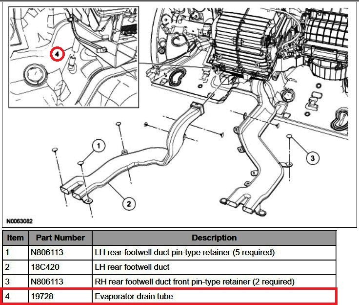
Surprisingly, it appears from the 2016 Edge/2016 MKX Workshop Manuals and also from Ford's FordParts website, that no drain tube is installed. Component descriptions and removal & installation procedures (attached as PDF download links below) from the Workshop Manual contain no mention or illustration of a drain tube... Climate Control System - Dual Automatic Temperature Control (DATC) - System Operation and Component Description - 2016 Edge Workshop Manual.pdf Heater Core and Evaporator Core Housing - Removal and Installation - 2016 Edge Workshop Manual.pdf Evaporator - Removal and Installation - 2016 Edge Workshop Manual.pdf Evaporator Inlet and Outlet Manifold - 2.7L EcoBoost (238kW-324PS) - Removal and Installation - 2016 Edge Workshop Manual.pdf Heater Core - Removal and Installation - 2016 Edge Workshop Manual.pdf Additionally, the illustration of the Heater Core and Evaporator Core Housing (19B555) and associated parts on the FordParts website shows no drain tube... In contrast to these 2016 Edge/MKX resources, the GEN1+ 2014 Edge Workshop Manual includes a Climate Control Housing illustration which calls out and includes its drain tube part number... detail Also, Workshop Manual removal and installation procedures detail the removal of the drain tube prior to removal of the larger housing component. Additionally, the FordParts website includes an image of the built-up housing assembly clearly showing the drain tube (red arrow) described above... Searching FordParts with 2016 Edge as the target vehicle for the 19728 Drain Tube yields 'This part does not match your vehicle', while designating the part number fits 2007-2014 Edge and 2007-2015 MKX. Good luck!andassociatedpartsontheFordParts.jpg.579bbc4f3a6338f3ebbb1067914f392a.jpg)
ImageontheFordParts.thumb.jpg.35311a9abe9298dfdcd8eca43f51012e.jpg)
-
Lost brake while driving; scary, concerning.
Haz replied to Edgingage's topic in Brakes, Chassis & Suspension
If you can scan your Edge -- or have it scanned at a local auto parts store (sometimes at no cost), these brake-related Diagnostic Trouble Codes (DTCs) may indicate ABS module failure and/or HCU failure requiring component replacement(s)... DTC Charts NOTE: This module utilizes a 5-character DTC followed by a 2-character failure type code. The failure type code provides information about specific fault conditions such as opens or shorts to ground. Continuous Memory Diagnostic Trouble Codes (CMDTCs) have an additional 2-character DTC status code suffix to assist in determining DTC history. ABS Module DTC Chart DTC Description Action C0001:49 TCS Control Channel "A" Valve 1: Internal Electronic Failure This DTC indicates that part of the ABS module has failed internally. CLEAR the DTCs. REPEAT the self-test. If DTC C0001:49 returns: For vehicles without adaptive cruise control, INSTALL a new ABS module. REFER to Anti-Lock Brake System (ABS) Module in this section. TEST the system for normal operation. For vehicles with adaptive cruise control, INSTALL a new HCU . REFER to Hydraulic Control Unit (HCU) in this section. TEST the system for normal operation. C0002:49 TCS Control Channel "A" Valve 2: Internal Electronic Failure This DTC indicates that part of the ABS module has failed internally. CLEAR the DTCs. REPEAT the self-test. If DTC C0002:49 returns: For vehicles without adaptive cruise control, INSTALL a new ABS module. REFER to Anti-Lock Brake System (ABS) Module in this section. TEST the system for normal operation. For vehicles with adaptive cruise control, INSTALL a new HCU . REFER to Hydraulic Control Unit (HCU) in this section. TEST the system for normal operation. C0003:49 TCS Control Channel "B" Valve 1: Internal Electronic Failure This DTC indicates that part of the ABS module has failed internally. CLEAR the DTCs. REPEAT the self-test. If DTC C0003:49 returns: For vehicles without adaptive cruise control, INSTALL a new ABS module. REFER to Anti-Lock Brake System (ABS) Module in this section. TEST the system for normal operation. For vehicles with adaptive cruise control, INSTALL a new HCU . REFER to Hydraulic Control Unit (HCU) in this section. TEST the system for normal operation. C0004:49 TCS Control Channel "B" Valve 2: Internal Electronic Failure This DTC indicates that part of the ABS module has failed internally. CLEAR the DTCs. REPEAT the self-test. If DTC C0004:49 returns: For vehicles without adaptive cruise control, INSTALL a new ABS module. REFER to Anti-Lock Brake System (ABS) Module in this section. TEST the system for normal operation. For vehicles with adaptive cruise control, INSTALL a new HCU . REFER to Hydraulic Control Unit (HCU) in this section. TEST the system for normal operation. C0010:49 Left Front Inlet Control: Internal Electronic Failure This DTC indicates that part of the ABS module has failed internally. CLEAR the DTCs. REPEAT the self-test. If DTC C0010:49 returns: For vehicles without adaptive cruise control, INSTALL a new ABS module. REFER to Anti-Lock Brake System (ABS) Module in this section. TEST the system for normal operation. For vehicles with adaptive cruise control, INSTALL a new HCU . REFER to Hydraulic Control Unit (HCU) in this section. TEST the system for normal operation. C0011:49 Left Front Outlet Control: Internal Electronic Failure This DTC indicates that part of the ABS module has failed internally. CLEAR the DTCs. REPEAT the self-test. If DTC C0011:49 returns: For vehicles without adaptive cruise control, INSTALL a new ABS module. REFER to Anti-Lock Brake System (ABS) Module in this section. TEST the system for normal operation. For vehicles with adaptive cruise control, INSTALL a new HCU . REFER to Hydraulic Control Unit (HCU) in this section. TEST the system for normal operation. C0014:49 Right Front Inlet Control: Internal Electronic Failure This DTC indicates that part of the ABS module has failed internally. CLEAR the DTCs. REPEAT the self-test. If DTC C0014:49 returns: For vehicles without adaptive cruise control, INSTALL a new ABS module. REFER to Anti-Lock Brake System (ABS) Module in this section. TEST the system for normal operation. For vehicles with adaptive cruise control, INSTALL a new HCU . REFER to Hydraulic Control Unit (HCU) in this section. TEST the system for normal operation. C0015:49 Right Front Outlet Control: Internal Electronic Failure This DTC indicates that part of the ABS module has failed internally. CLEAR the DTCs. REPEAT the self-test. If DTC C0015:49 returns: For vehicles without adaptive cruise control, INSTALL a new ABS module. REFER to Anti-Lock Brake System (ABS) Module in this section. TEST the system for normal operation. For vehicles with adaptive cruise control, INSTALL a new HCU . REFER to Hydraulic Control Unit (HCU) in this section. TEST the system for normal operation. C0018:49 Left Rear Inlet Control: Internal Electronic Failure This DTC indicates that part of the ABS module has failed internally. CLEAR the DTCs. REPEAT the self-test. If DTC C0018:49 returns: For vehicles without adaptive cruise control, INSTALL a new ABS module. REFER to Anti-Lock Brake System (ABS) Module in this section. TEST the system for normal operation. For vehicles with adaptive cruise control, INSTALL a new HCU . REFER to Hydraulic Control Unit (HCU) in this section. TEST the system for normal operation. C0019:49 Left Rear Outlet Control: Internal Electronic Failure This DTC indicates that part of the ABS module has failed internally. CLEAR the DTCs. REPEAT the self-test. If DTC C0001:49 returns: For vehicles without adaptive cruise control, INSTALL a new ABS module. REFER to Anti-Lock Brake System (ABS) Module in this section. TEST the system for normal operation. For vehicles with adaptive cruise control, INSTALL a new HCU . REFER to Hydraulic Control Unit (HCU) in this section. TEST the system for normal operation. C001C:49 Right Rear Inlet Control: Internal Electronic Failure This DTC indicates that part of the ABS module has failed internally. CLEAR the DTCs. REPEAT the self-test. If DTC C001C:49 returns: For vehicles without adaptive cruise control, INSTALL a new ABS module. REFER to Anti-Lock Brake System (ABS) Module in this section. TEST the system for normal operation. For vehicles with adaptive cruise control, INSTALL a new HCU . REFER to Hydraulic Control Unit (HCU) in this section. TEST the system for normal operation. C001D:49 Right Rear Outlet Control: Internal Electronic Failure This DTC indicates that part of the ABS module has failed internally. CLEAR the DTCs. REPEAT the self-test. If DTC C001D:49 returns: For vehicles without adaptive cruise control, INSTALL a new ABS module. REFER to Anti-Lock Brake System (ABS) Module in this section. TEST the system for normal operation. For vehicles with adaptive cruise control, INSTALL a new HCU . REFER to Hydraulic Control Unit (HCU) in this section. TEST the system for normal operation. C0020:11 ABS Pump Motor Control: Circuit Short To Ground This DTC indicates that part of the HCU has failed internally. CLEAR the DTCs. TEST DRIVE the vehicle. REPEAT the self-test. If C0020:11 returns, INSTALL a new HCU . REFER to Hydraulic Control Unit (HCU) in this section. TEST the system for normal operation. C0020:12 ABS Pump Motor Control: Circuit Short To Battery This DTC indicates that part of the HCU has failed internally. CLEAR the DTCs. TEST DRIVE the vehicle. REPEAT the self-test. If C0020:12 returns, INSTALL a new HCU . REFER to Hydraulic Control Unit (HCU) in this section. Additional Workshop Manual resources on ABS Module and HCU as PDF download links... Anti-Lock Brake System (ABS) Description and Anti-Lock Control Operation - 2011 Edge Workshop Manual.pdf Anti-Lock Brake System (ABS) and Anti-Lock Control Diagnosis and Testing - 2011 Edge Workshop Manual.pdf Anti-Lock Brake System (ABS) Module Location Illustration - 2011 Edge Workshop Manual.pdf Anti-Lock Brake System (ABS) Module - Removal and Installation - 2011 Edge Workshop Manual.pdf Hydraulic Control Unit (HCU) - Removal and Installation - 2011 Edge Workshop Manual.pdf Anti-Lock Brake System (ABS) Module Wiring Connector C135 Details - 2011 Edge Workshop Manual.pdf The failure of the brake booster in our 2012 MKX initially exhibited normal boost-assist, but with a somewhat lower pedal height for about three weeks without any audible symptom. The catastrophic failure happened at stop sign, where the pedal went all the way to the floor, with braking only occurring with very high stand-on-it effort level, and a noticeable hissing noise when the pedal was at floor level. At no time did normal braking behavior reappear, until after the brake booster was replaced. Driving it to the dealership, there was no boost or progression to braking -- just high effort and harsh braking at floor level. Good luck!- 4 replies
-
- 1
-

-
- brake lost
- lost brakes
- (and 1 more)
-
TSB 22-2309 - Modem Authorization/Remote Commands/Location Issues In App After 3G To 4G Modem Upgrade - 8 Inch Or Larger Center Display Screen This bulletin supersedes 22-2230. Model: Ford 2013-2017 C-MAX Energi 2013-2018 Focus BEV 2013-2020 Fusion PHEV Lincoln 2017 Continental 2015-2017 MKC 2016-2017 MKX 2015-2017 MKZ 2015-2017 MKZ Hybrid Summary This article supersedes TSB 22-2230 to update the Issue and Action. Issue: Some 2013-2017 C-MAX Energi, 2013-2018 Focus battery electric vehicle (BEV), 2013-2020 Fusion plug-in hybrid electric vehicle (PHEV), 2015-2017 MKZ/MKZ Hybrid/MKC, 2016-2017 MKX and 2017 Continental vehicles equipped with 8 inch or larger center display screen may be unable to complete modem authorization after 3G to 4G modem upgrade was performed. No Authorization Pop-up will be displayed on the center display screen during the Authorization process. The vehicle may also not have proper functionality of remote app features such as remote start, return odometer, fuel information, or vehicle location incorrect in the app. This may be due to the SYNC software. To correct the condition, follow the Service Procedure to toggle Valet Mode. Action: Follow the Service Procedure to correct the condition on vehicles that meet all of the following criteria: • One of the following vehicles: Warranty Status: Eligible under provisions of New Vehicle Limited Warranty (NVLW)/Service Part Warranty (SPW)/Special Service Part (SSP)/Extended Service Plan (ESP) coverage. Limits/policies/prior approvals are not altered by a TSB. NVLW/SPW/SSP/ESP coverage limits are determined by the identified causal part and verified using the OASIS part coverage tool. Labor Times Description Operation No. Time Perform A PMI On The TCU And Toggle The Valet Mode Following The Service Procedure (Do Not Use With Any Labor Operations Outside Of This Article) 222309A 0.4 Hrs. 2017 C-MAX Energi: Check For Later Version Of IPC Software And Install (Can be Claimed With Operation A) MT222309 Actual Time Repair/Claim Coding Causal Part: 14G229 Condition Code: 04 Service Procedure NOTE: During the new 3G to 4G modem upgrade, the Integrated Diagnostic System (IDS) scan tool must be at software level 126.04 or higher and connected to the internet. 1. Start a new IDS session for the vehicle. NOTE: Do not use a previous session for the VIN. If the IDS asks to select a prior session, choose None of the Above. 2. Perform a programmable module installation (PMI) on the telematics control unit (TCU). 3. For 2017 C-Max Energi vehicles, check for a later version of instrument panel cluster (IPC) software and install the latest software if available. 4. Turn the ignition key to the ON position. 5. Access valet mode in the center display screen, Settings > Vehicle > Valet Mode, or Settings > Valet Mode. 6. Enable (turn on) valet mode, when prompted, enter universal PIN 3681. Repeat the same PIN as necessary. 7. Turn the ignition key to the OFF position, allowing the center display screen to fully power down. 8. Turn the ignition key to the ON position. 9. Disable (turn off) valet mode. (1). To disable (turn off) valet mode, when prompted, enter universal PIN 3681. Repeat the same PIN as necessary. 10. Turn the ignition key to the OFF position, allowing the center display screen to fully power down. 11. Using the latest version of the FordPass or LincolnWay app, remove and then re-add the VIN to the mobile app. NOTE: The same VIN can be used in multiple FordPass or LincolnWay devices. Any mobile device that might have previously had the VIN in the mobile app needs to have the VIN removed and then added back for proper remote functionality to return. 12. Select Allow when the pop-up appears on the center display screen. If no pop-up appears, repeat the previous steps to enable/disable valet mode. 13. Perform a remote lock/unlock and a remote start from the mobile app. TSB 22-2309 - 2016-2017 MKX + Other Models - Modem Authorization-Remote Commands-Location Issues In App After 3G To 4G Modem Upgrade - 8 Inch Or Larger Center Display Screen - August 2, 2022.pdf
-
need more power on the wireless charging pad
Haz replied to ben senise's topic in Audio, Backup, Navigation & SYNC
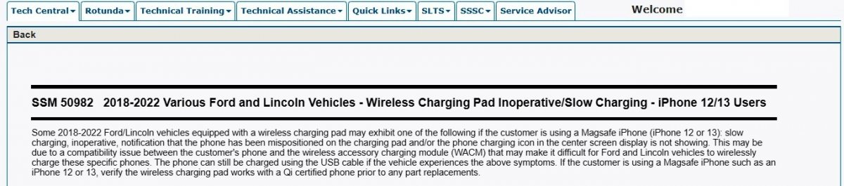
SSM 50982 was first displayed yesterday on the opening screen of Ford's secure (valid User ID & Password required) Professional Technician System website as an OASIS Broadcast Message, dated August 1, 2022... Since yesterday, additional OASIS messages have been added, so they will have to scroll down if they are looking for it on the PTS website opening screen. It is the third of three OASIS Broadcast Messages that are dated August 1, 2022... It is valid, and, if you provide this locating advice, they should easily find it. Good luck!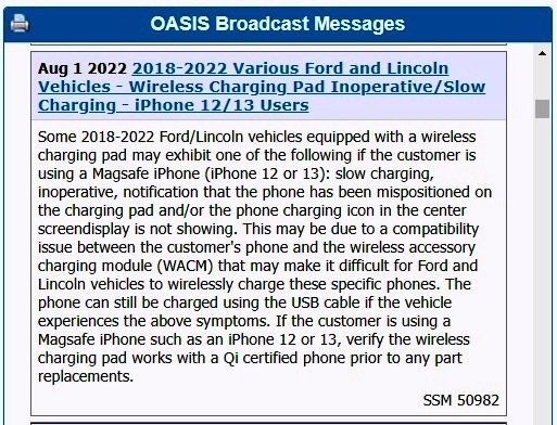
-
Sync 4A disasters, am I the only one?
Haz replied to Xfire's topic in Audio, Backup, Navigation & SYNC
The referenced & recent ambient lighting discussion, started by Davidoo... Ambient lighting won't stay on. Good luck! -
I have offered my reply on the duplicate post in the Brakes, Chassis & Suspension forum, in order to facilitate future searches for information by topic. Good luck!
- 1 reply
-
- 1
-

-
Lost brake while driving; scary, concerning.
Haz replied to Edgingage's topic in Brakes, Chassis & Suspension
No similar experience apart from your description of failed brake booster symptoms in our 2012 MKX, which was replaced under the 13N02 warranty extension. To provide you a starting point, the following is a partial symptom list edited to include your Edge's brake system behavior, from the 2011 Edge Workshop Manual... ion procedures don't In addition, below as PDF download links are relevant sections from the Workshop Manual that provide the same inspection and evaluation guidance that a dealership technician would employ toward a potential $200 review of your Edge's brake system. Many of the evaluation steps involve inspection & performance observation and do not initially require disassembly of components, though component removal procedures are also included... Brake System Symptom Chart - Brake System Diagnosis and Testing - 2011 Edge Workshop Manual.pdf Brake System Inspection - Brake System General Procedures - 2011 Edge Workshop Manual.pdf Brake System Component Tests - Brake System Diagnosis and Testing - 2011 Edge Workshop Manual.pdf Power Brake Booster - Removal and Installation - 2011 Edge Workshop Manual.pdf Brake Master Cylinder - Removal and Installation - 2011 Edge Workshop Manual.pdf Brake Pedal and Bracket - Removal and Installation - 2011 Edge Workshop Manual.pdf Stoplamp Switch - Removal and Installation - 2011 Edge Workshop Manual.pdf If your efforts reveal a questionable condition that you prefer not to address yourself, at least you'll be able to speak with your dealer about what you looked at and found, perhaps allowing their diagnosis to occur more quickly and less expensively. Good luck!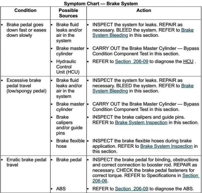
- 4 replies
-
- 4
-
-
-
- brake lost
- lost brakes
- (and 1 more)
-
need more power on the wireless charging pad
Haz replied to ben senise's topic in Audio, Backup, Navigation & SYNC
Ford is acknowledging possible wireless charging compatibility issues with iPhone 12 & 13... SSM 50982 2018-2022 Various Ford and Lincoln Vehicles - Wireless Charging Pad Inoperative/Slow Charging - iPhone 12/13 Users Some 2018-2022 Ford/Lincoln vehicles equipped with a wireless charging pad may exhibit one of the following if the customer is using a Magsafe iPhone (iPhone 12 or 13): slow charging, inoperative, notification that the phone has been mispositioned on the charging pad and/or the phone charging icon in the center screen display is not showing. This may be due to a compatibility issue between the customer's phone and the wireless accessory charging module (WACM) that may make it difficult for Ford and Lincoln vehicles to wirelessly charge these specific phones. The phone can still be charged using the USB cable if the vehicle experiences the above symptoms. If the customer is using a Magsafe iPhone such as an iPhone 12 or 13, verify the wireless charging pad works with a Qi certified phone prior to any part replacements. Good luck! -
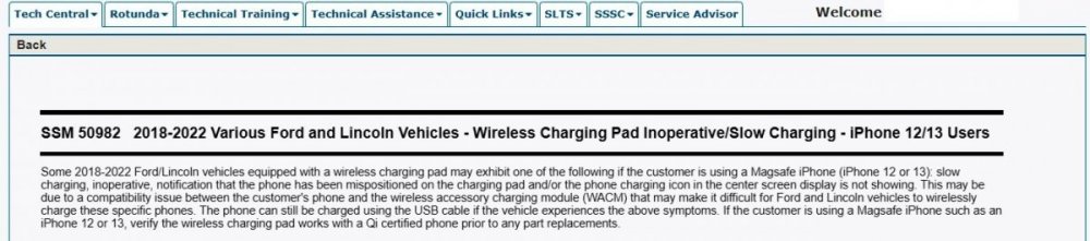
SSM 50982 2018-2022 Various Ford and Lincoln Vehicles - Wireless Charging Pad Inoperative/Slow Charging - iPhone 12/13 Users Some 2018-2022 Ford/Lincoln vehicles equipped with a wireless charging pad may exhibit one of the following if the customer is using a Magsafe iPhone (iPhone 12 or 13): slow charging, inoperative, notification that the phone has been mispositioned on the charging pad and/or the phone charging icon in the center screen display is not showing. This may be due to a compatibility issue between the customer's phone and the wireless accessory charging module (WACM) that may make it difficult for Ford and Lincoln vehicles to wirelessly charge these specific phones. The phone can still be charged using the USB cable if the vehicle experiences the above symptoms. If the customer is using a Magsafe iPhone such as an iPhone 12 or 13, verify the wireless charging pad works with a Qi certified phone prior to any part replacements.
-
Did you mistype 2012, or are you driving a GEN1+ EcoBoost FrankenEdge? So that I may pull the proper diagnostic procedures: Is that a 2.0L or 2.7L ? The generic DTC descriptor from the 2022 Edge Workshop Manual... DTC Fault Trigger Conditions PCM P0299:00 Turbocharger/Supercharger 'A' Underboost Condition: No Sub Type Information Sets when the PCM detects the actual turbocharger boost pressure (TCBP) value is less than the desired turbocharger boost pressure (TCBP) value by 27.6 kPa (4 psi) or more for 5 seconds, indicating an under boost condition. Check tubing for restrictions, cracks and incorrect fitting connections. Check the turbocharger wastegate regulating valve solenoid for correct operation. Good luck!
-
2018 Ford Edge No Tweeter Wiring Rear Door
Haz replied to bhamraS97's topic in Audio, Backup, Navigation & SYNC
Possibly a misbuild outcome, where the wrong wiring harness was installed in the door at the Assembly Plant. If you have Ford ESP/Ford Protect extended warranty -- or even if you don't, it may be worth checking with your dealer. Good luck! -
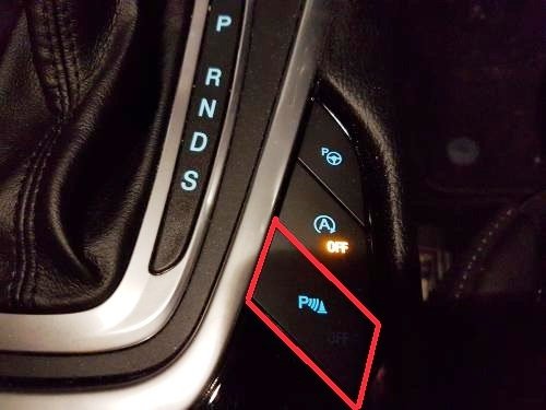
Providing confirmation to akirby's wise view on the Parking Aid Disable Switch, from the 2015 Edge Owner's Manual online/HTML version (link to website), information that is not included in the printed Owner's Manual... Good luck!
Version.thumb.jpg.75bc54a67375467e922be530dd505df2.jpg)
-
No brake lights and can't shift out of park
Haz replied to myf16's topic in Brakes, Chassis & Suspension
Below are PDF download links to relevant sections of the 2009 Edge Workshop Manual... If you require specific connector details, let me know and I will provide you the information. Good luck! Turn Signal-Stop-Hazard Lamps Wiring Diagram 1 - 2009 Edge Workshop Manual.pdf Turn Signal-Stop-Hazard Lamps Wiring Diagram 2 - 2009 Edge Workshop Manual.pdf Stop Lamps Diagnosis and Testing - 2009 Edge Workshop Manual.pdf Stop Lamps Switch Removal and Installation - 2009 Edge Workshop Manual.pdf Brake-Shift Interlock Description and Operation - 2009 Edge Workshop Manual.pdf -
Below are PDF download links to relevant sections of the 2014 Edge Workshop Manual, relating to Power Liftgate operation, diagnostics including Diagnostic Trouble Code (DTC) and Symptom lists, wiring diagrams, and several major component removal and installation procedures. If your diagnostic efforts progress to steps requiring specific connector details beyond what the document offers, let me know and I will provide the connector information. Good luck! Power Liftgate Diagnosis and Testing - 2014 Edge Workshop Manual.pdf Power Liftgate Wiring Diagram - Page 1 - 2014 Edge Workshop Manual.pdf Power Liftgate Wiring Diagram - Page 2 - 2014 Edge Workshop Manual.pdf Power Liftgate Wiring Diagram - Page 3 - 2014 Edge Workshop Manual.pdf Power Liftgate Wiring Diagram - Page 4 - 2014 Edge Workshop Manual.pdf Power Liftgate Wiring Diagram - Page 5 - 2014 Edge Workshop Manual.pdf Power Liftgate Initialization - 2014 Edge Workshop Manual.pdf Power Liftgate Motor Removal and Installation - 2014 Edge Workshop Manual.pdf Liftgate-Trunk Module (LTM) Removal and Installation - 2014 Edge Workshop Manual.pdf
-
2018 Ford Edge No Tweeter Wiring Rear Door
Haz replied to bhamraS97's topic in Audio, Backup, Navigation & SYNC
Below as PDF download links are rear door speaker wiring diagram, speaker connector details, speaker removal & installation procedures, and in case you need it, door panel removal and installation procedures. The wiring diagram and connector detail appear to show the tweeter wiring jumps up from the door speaker connector. If you cannot locate the unconnected tweeter harness inside the door cavity, you could probably order the appropriate pigtail connector kit or use generic audio connector pins and the proper gauge wire indicated in the connector details to create your own tweeter harness extension from the door speaker connector. Good luck! Edge Sony Rear Door Audio Wiring Diagram - 2018 Edge Workshop Manual.pdf Rear Door Speaker Left Hand Driver's Side - Connector C702 - 2018 Edge Workshop Manual.pdf Rear Door Tweeter Speaker Left Hand-Driver's Side - Connector C730 Details - 2018 Edge Workshop Manual.pdf Rear Door Speaker Right Hand Pass Side - Connector C802 Details- 2018 Edge Workshop Manual.pdf Rear Door Tweeter Speaker Right Hand-Pass Side - Connector C830 Details - 2018 Edge Workshop Manual.pdf Rear Door Audio Connector Locations Left Hand-Driver's Side - 2018 Edge Workshop Manual.pdf Rear Door Audio Connector Locations Right Hand-Pass Side - 2018 Edge Workshop Manual.pdf Rear Door Speaker LH Removal and Installation - 2018 Edge Workshop Manual.pdf Rear Door Speaker RH Removal and Installation - 2018 Edge Workshop Manual.pdf Rear Door Tweeter Speaker Removal and Installation - 2018 Edge Workshop Manual.pdf Rear Door Trim Panel Removal and Installation - 2018 Edge Workshop Manual.pdf Rear Door Window Control Switch Removal and Installation - 2018 Edge Workshop Manual.pdf -
SSM 50975 2017-2022 Various Ford And Lincoln Vehicles - Deep Sleep Mode Notification In FordPass® And/Or LincolnWay® Cell Phone Apps Some 2017-2022 Ford/Lincoln customers may experience a notification in the FordPass®/LincolnWay® app indicating Vehicle Has Entered Deep Sleep Mode. This occurs when the vehicle has not been started for 14 consecutive days, battery voltage is at/below 9.5 volts or the body control module (BCM) 12 volt battery state of charge (SOC) drops below 50%. A warning may also set if the telematic control unit (TCU) has received an over the air update. The TCU powers down all communication when in this mode and app features are disabled. Manually start the vehicle to wake if from mode. More information is located in the app under: Account > Help > search 'Deep Sleep' in the entry box. If the condition remains, check the BCM 12v SOC. If the SOC does not change after charging the battery or after BMS reset is performed, continue with normal battery and/or BMS sensor diagnostics.
-
So, Hawaii is Ford Dealer Paradise too. Aloha!
-
Posting this to provide historical reference to timing of under-hood insulation discontinuance... SSM 50313 2019-2022 Edge - Under Hood Insulation No Longer Equipped - Built On Or After 7-Feb-2019 2019-2022 Edge SE and SEL vehicles built on or after 7-Feb-2019 and Edge ST and Titanium vehicles built on or after 2-May-2019 are no longer equipped with an insulation panel on the underside of the hood. The vehicle is not misbuilt. The addition of any parts is not a warrantable repair. Do not submit a claim for this condition.
-
Kclonn: Just noticed this, from November 30, 2021, regarding risk to the prospect of your dealer providing free under-hood insulation... SSM 50313 2019-2022 Edge - Under Hood Insulation No Longer Equipped - Built On Or After 7-Feb-2019 2019-2022 Edge SE and SEL vehicles built on or after 7-Feb-2019 and Edge ST and Titanium vehicles built on or after 2-May-2019 are no longer equipped with an insulation panel on the underside of the hood. The vehicle is not misbuilt. The addition of any parts is not a warrantable repair. Do not submit a claim for this condition. Good luck!
-
Welcome to the Forum! Input you Edge's VIN into this Ford website to determine if your Edge has any outstanding Field Service Actions, looking especially for 13N02 Brake Booster Extended Warranty coverage, which may be expiring soon for many vehicles, based upon new vehicle purchase date. If 13N02 is not listed, then your Edge has already received a new Brake Booster after the failure of the originally-installed component, so that's good news. The following is a PDF download link to the document sent to original owners - 13N02 - Brake Booster Warranty Extension - 2010 thru 2013 Edge and MKX.pdf Good luck!
-
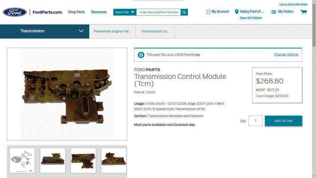
While the below FordParts web page describes it as 'Transmission Control Module' for (GEN1/GEN1+) 6F50 transmissions, Factory Service Manuals thru 2022 term it as 'Solenoid Body', with the 2008 Edge Workshop Manual providing this programming and functional traits description: Solenoid Body NOTICE: If the solenoid body identification and strategy does not match the solenoid body information in the Powertrain Control Module (PCM), transaxle damage or driveability concerns can occur. The solenoid body contains 7 solenoids, 5 shift solenoids [Shift Solenoid A (SSA) , Shift Solenoid B (SSB) , Shift Solenoid C (SSC) , Shift Solenoid D (SSD) and Shift Solenoid E (SSE)]. TCC solenoid and LPC solenoid. The Transmission Fluid Temperature (TFT) is also located in the solenoid body. The solenoid body is serviced as an assembly. The solenoid body has a unique strategy data file that must be downloaded to the PCM. there is a 7-digit solenoid body identification and a 13-digit solenoid body strategy for each solenoid body. Anytime a new solenoid body is installed or the transaxle is installed, the scan tool must be used to get the solenoid body strategy data file and download it into the PCM. If the PCM is replaced and the PCM data can not be inhaled or exhaled, the solenoid body identification and solenoid body strategy must be downloaded into the PCM. Shift Solenoid A (SSA) , Shift Solenoid B (SSB) , Shift Solenoid C (SSC) , Shift Solenoid D (SSD) and Shift Solenoid E (SSE) Five shift solenoids are used for electronic shift scheduling. The 5 solenoids are located in the solenoid body. SSA , SSB , SSC and SSD are Variable Force Solenoid (VFS) . SSE is an ON/OFF shift solenoid. Shift solenoids SSA , SSB , SSC , SSD and SSE provide selection of 1st through 6th gears and reverse by controlling the pressure of the shift valves. SSA and SSC are normally low-pressure solenoids. Pressure increases as the PCM activates the solenoid. SSB and SSD are normally high-pressure solenoids. Pressure decreases as the PCM activates the solenoid. SSE is normally closed and opens when the PCM activates the solenoid. The solenoids are activated by the PCM controlling current flow at the solenoid ground circuit, this is known as ground side switching. Thanks for your question, which provided me this learning opportunity. Good luck!

ImageontheFordParts.jpg.e2e38bb873f15b944b62f194ce56e446.jpg)
Version.jpg.e319e4364fc5759445a2595f473c911d.jpg)