Haz
-
Posts
1,468 -
Joined
-
Last visited
-
Days Won
393
Everything posted by Haz
-
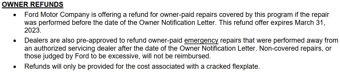
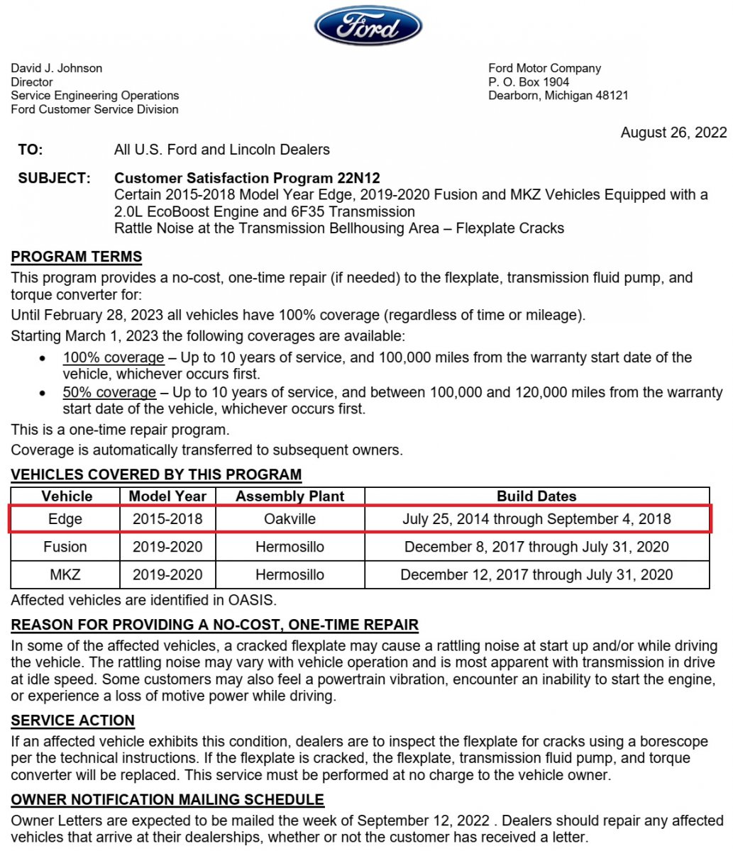
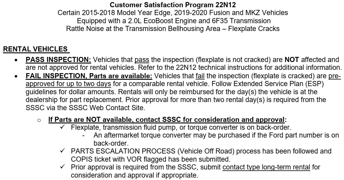
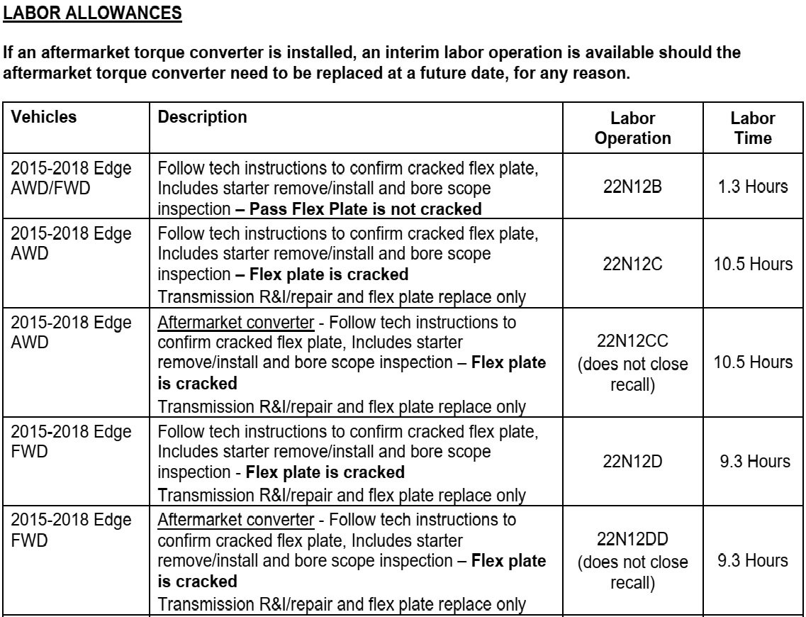
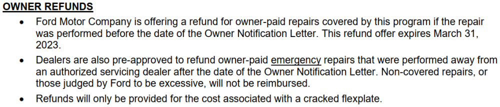
Customer Satisfaction 22N12- Flex Plate Crack on 2.0
Haz replied to All Hat No Cattle's topic in Recalls, TSBs & Warranty
-
From the 2014 Edge Workshop Manual, as a PDF download link... Front Fender Removal and Installation - 2014 Edge Workshop Manual.pdf Good luck!
-
Relating to installation of a new battery and the Battery Monitoring System (BMS), from the 2011 Edge Workshop Manual... Carry out the Battery Monitoring System (BMS) Reset using the scan tool after the battery is connected. If the BMS Reset is not carried out, it takes approximately 8 hours for the Body Control Module (BCM) to learn the new battery state of charge. During this 8 hour period, the vehicle must be undisturbed, with no doors opened or keyless entry button presses. If the vehicle is used before the BCM is allowed to learn the new battery state of charge, engine off load shedding can still occur and a message may be displayed. Good luck!
-
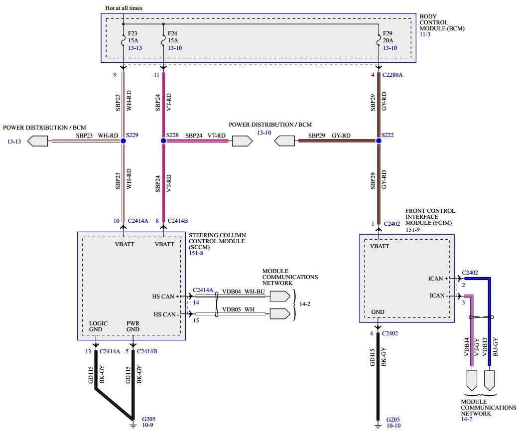
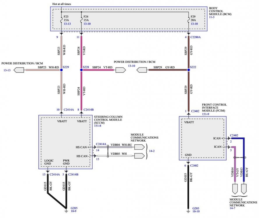
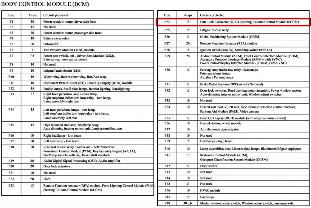
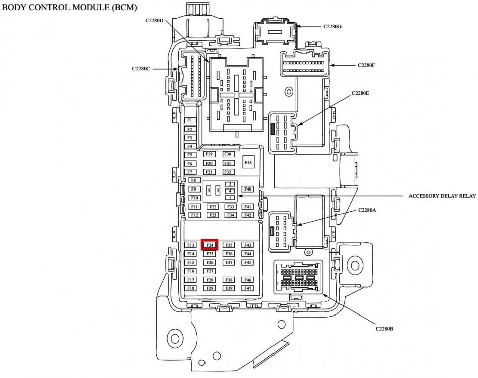
From the 2011 Edge Workshop Manual... Steering Wheel Controls [Message Center & Entertainment context description] The steering wheel controls are mounted directly to the steering wheel and wired to the Steering Column Control Module (SCCM) . Depending on what features the vehicle is equipped with, the SCCM sends messages via the High Speed Controller Area Network (HS-CAN) to the PCM (cruise control) and the Instrument Panel Cluster (IPC) (message center and entertainment system). The IPC receives the SCCM entertainment system messages via the HS-CAN and then sends them to the applicable entertainment system module(s) along the Infotainment Controller Area Network (I-CAN) . Steering Wheel Controls [Audio context description] The steering wheel controls consist of a series of resistors. Each steering wheel control switch function corresponds with a specific resistance value within the switch. When a switch is pressed, the Steering Column Control Module (SCCM) monitors the change in reference voltage to determine the requested function. The SCCM communicates the switch inputs in a message to the IPC over the HS-CAN . The IPC gateways the message to the ACM and other audio modules over the I-CAN . For Edge base and premium audio systems without SYNC®, the FCDIM serves as the infotainment display. The 5-way RH steering wheel switch controls and navigates the menus in the FCDIM . Steering Wheel Controls wiring diagram Steering Column Control Module (SCCM) Wiring Diagram Per the SCCM wiring diagram and the BCM fuse/circuits chart, fuse F24 is associated with the SCCM, so take a look at the condition of F24 in the same way you did F23. Do you have access to a scanner or a laptop with Forscan, or a phone with Forscan Lite, and an OBDII-compatible Data Link connector, in order to check your Edge for Diagnostic Trouble Codes (DTCs) that may identify current or past issues caused by the failing/failed battery? A scanner or Forscan-equivalent device could also be used to evaluate the functioning of the steering wheel switches in real-time. Good luck!

-
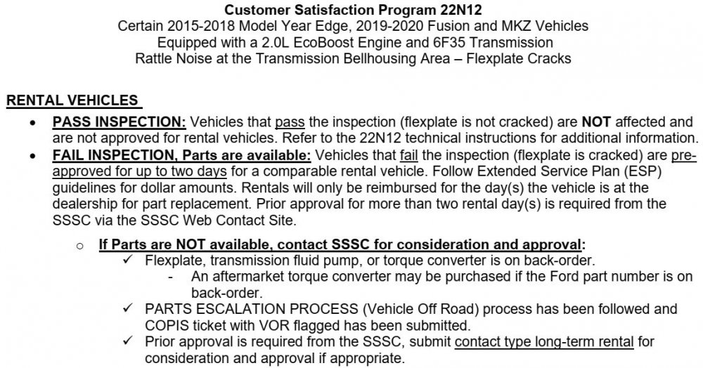
Customer Satisfaction 22N12- Flex Plate Crack on 2.0
Haz replied to All Hat No Cattle's topic in Recalls, TSBs & Warranty
Additional info... Technical Information document download link... Customer Satisfaction Program 22N12 - Technical Info.pdf Good luck!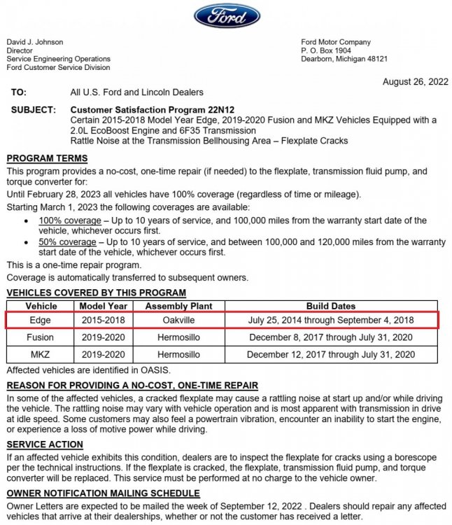

-
Below as PDF download links are PCM-related sections of the 2007 Edge Workshop Manual... Electronic Engine Controls - Description and Operation - 2007 Edge Workshop Manual.pdf POWERTRAIN CONTROL MODULE (PCM) - Removal and Installation - 2007 Edge Workshop Manual.pdf POWERTRAIN CONTROL MODULE (PCM) - Connector C175B Details - 2007 Edge Workshop Manual.pdf POWERTRAIN CONTROL MODULE (PCM) - Connector C175E Details - 2007 Edge Workshop Manual.pdf POWERTRAIN CONTROL MODULE (PCM) - Connector C175T Details - 2007 Edge Workshop Manual.pdf POWERTRAIN CONTROL MODULE (PCM) - Connectors C175B-C175E-C175T Location Illustration - 2007 Edge Workshop Manual.pdf Engine Controls Wiring Diagram 1 - 2007 Edge Workshop Manual.pdf Engine Controls Wiring Diagram 2 - 2007 Edge Workshop Manual.pdf Engine Controls Wiring Diagram 3 - 2007 Edge Workshop Manual.pdf Engine Controls Wiring Diagram 4 - 2007 Edge Workshop Manual.pdf Engine Controls Wiring Diagram 5 - 2007 Edge Workshop Manual.pdf Engine Controls Wiring Diagram 6 - 2007 Edge Workshop Manual.pdf Engine Controls Wiring Diagram 7 - 2007 Edge Workshop Manual.pdf Engine Controls Wiring Diagram 8 - 2007 Edge Workshop Manual.pdf Engine Controls Wiring Diagram 9 - 2007 Edge Workshop Manual.pdf Engine Controls Wiring Diagram 10 - 2007 Edge Workshop Manual.pdf Engine Controls Wiring Diagram 11 - 2007 Edge Workshop Manual.pdf Engine Controls Wiring Diagram 12 - 2007 Edge Workshop Manual.pdf Good luck!
-
Forum member Bill Trammell offers many useful water pump videos on his MACT Ford Edge YouTube channel. Good luck!
-
Three instances of 'PVC' corrected, though modifying the document seems nearly as egregious as modifying a PCV System. Good luck!
-
GENERAL SERVICE BULLETIN Various Vehicles - Gas Engine Performance Modifications 22-7077 23 May 2022 This bulletin supersedes 20-7094. Summary This article supersedes GSB 20-7094 to update the vehicle model years affected. This bulletin is intended to be used by technicians when servicing vehicles that have suspected aftermarket modifications. If an aftermarket modification can be associated with the need for a repair, that repair may not be warrantable. To make this determination, the technician should refer to the aftermarket modifications flowchart within this document. Service Information The following information supplement the flowchart through pictures and descriptions of common aftermarket modifications and possible associated failures. This document is not all inclusive and other aftermarket modifications may exist that are not covered here. Note that sections listed as “Universal” are applicable to all engine families. If additional repair assistance is needed, the technician should refer to PTS > Technical Assistance > Service Repair and Technical Support > Service Repair and Technical Support. Below is the modification flowchart for a vehicle that exhibits a failure that leads to suspicion of unauthorized aftermarket modifications. 1. Determine the failure conditions. Use a borescope to inspect the piston crowns and bore walls. Examine the damaged components. Refer to the Common Failure Modes section later in this article. 2. Retrieve diagnostic trouble codes (DTCs). Do not clear the DTCs. 3. Were any DTCs retrieved? (1). Yes - proceed to Step 4. (2). No - proceed to Step 6. 4. Do the DTCs explain the failure? (1). Yes - proceed to Step 5. (2). No - proceed to Step 6. 5. Are misfire code present? (1). Yes - proceed to Step 6. (2). No - follow normal diagnostics and/or repair procedures. repair under warranty. Flowchart is complete. 6. Has original equipment manufacturer (OEM) calibration been modified? Refer to the Aftermarket Calibrations section later in this article. (1). Yes - proceed to Step 7. (2). No - proceed to Step 8. 7. Is the failure consistent with aftermarket calibration? Refer to the Aftermarket Calibrations section later in this article. (1). Yes - engine repair not covered under warranty. Refer to the Warranty and Policy Manual on FMCDealer.com. Flowchart is complete. (2). No - proceed to Step 8. 8. Inspect for hardware modifications. Is there any hardware present that could cause the failure? Refer to applicable sections later in this article. (1). Yes - engine repair not covered under warranty. Refer to the Warranty and Policy Manual on FMCDealer.com. (2). No - repair under warranty. Service Guidelines Inform owners that the current factory approved and certified calibrations adjust fuel and spark settings for maximum performance with production hardware, while protecting the engine over a wide range of operating conditions. This includes a knock sensor calibration enabling optimized performance based on fuel grade usage. See the Owner's Manual for details. Aftermarket hardware and calibrations risk damage to engine and transmission assemblies. Unauthorized calibration modifications may or may not be detectable using standard tools such as a Ford diagnostic scan tool. Changes can be made to the calibration and flashed to the powertrain control module (PCM) through the on-board diagnostics (OBD) port. Physical modifications to the hardware may or may not be present. If aftermarket power/torque-increasing modifications are suspected, care should be taken to record and store the following items: permanent diagnostic trouble codes (DTCs), pending DTCs, freeze frame data, mode 6 and mode 9 data. The data should be printed and attached to the repair order for later reference. The DTCs, freeze frame data, mode 6 and 9 data can be obtained by using the IDS under the tool box selection. The Powertrain tab will provide the OBD test modes tab and mode 6 and 9 data selection after the vehicle has been identified. Attempting to increase the engine output via recalibrating the PCM may result in poor drivability, DTCs, or premature component failures. Common DTCs associated with aftermarket mods: • P0300-P0308 (engine misfire) • P0605 (read only memory error) • P0325, P130D (engine knock) • P0420, P0430 (catalyst temperature) • P0171, P0174 (lean air-fuel ratio) The following aftermarket brands are covered under a separate warranty through Ford Performance: • Ford Performance • Ford Racing • Mountune If parts from any of these brands appear on the vehicle, refer to OASIS to confirm installation and for warranty information. Common Failure Modes This section contains common failure conditions that are seen in vehicles with aftermarket modifications. Technicians should compare the failure modes found in the vehicle being serviced to the conditions presented in this section. The aftermarket modifications that may have contributed to these failure conditions can be found in Section C. Universal Failure Modes - Failures found in all engine families Piston Damage From Pre-Ignition Scored cylinder wall. (Figure 1) Figure 1 Piston ring land damage. (Figure 2) Figure 2 Piston damage from pre-ignition. (Figure 3) Figure 3 Borescope view of piston damage and cylinder scoring. (Figure 4) Figure 4 Description: Damage to piston profiles can often be attributed to pre-ignition (knock) events. OEM calibrations will protect the engine from pre-ignition damage by retarding spark. Aftermarket calibrations will typically change timing schedules and allow the engine to run closer to damage limits. Pre-ignition along with extreme air-fuel ratios and excessive oil consumption may also damage catalyst material. This material can then be pulled back into the engine, scoring the cylinder bore walls. Possible causes: • Aftermarket calibration • Turbo modifications • Exhaust system modifications • Catalyst damage • Low quality fuel Piston Ring And Spark Plug Damage Piston ring damage. (Figure 5) Figure 5 Ring land damage. (Figure 6) Figure 6 Spark plug ground electrode damage. (Figure 7) Figure 7 Spark plug damage and abnormal color. (Figure ? Figure 8 Description: Similar to the pre-ignition piston damage, piston rings can also be damaged from preignition (knock) events. OEM calibrations will protect the engine from pre-ignition damage by retarding spark. Aftermarket calibrations will typically change timing schedules and allow the engine to run closer to damage limits. Damage to the top piston ring may exhibit in the form of delamination, pitting or fracture. Spark plug damage as shown in the figures above can be another indicator of an aftermarket calibration, changes to the vehicle induction system , or other revisions that can increase combustion temperatures. This is especially true when the plugs show rapid degradation in all cylinders as shown in Figure 8. Possible causes: • Excessive spark advance from aftermarket calibration • Excessive spark advance from changes in induction system Connecting Rod Damage Bent connecting rod from hydrolock. (Figure 9) Figure 9 Description: Hydrolock occurs when a volume of liquid greater than the smallest volume of the combustion chamber enters the cylinder and becomes incompressible as the piston reaches Top Dead Center. The result is most commonly a bent or broken connecting rod. Connecting rod damage may also be caused by excessive cylinder pressure (overboost condition) and may not be obvious via visual inspection. Connecting rod twisting can lead to bore scoring and eventual piston failure. Note that connecting rod bends or twists may not be obvious visually, but can still contribute to engine damage or failure. Possible causes: • Leaking fuel injectors • Rerouted air induction systems that show evidence of water ingestion • Turbocharger modifications • Supercharger modifications Torque Converter Damage Normal converter on the left, overheated converter on the right. (Figure 10) Figure 10 Description: Overheated torque converters will exhibit discoloration. Possible causes: • Any aftermarket modification that increases torque or power output may cause the torque converter to overheat. Automatic Transmission Clutch Damage Damaged clutch discs. (Figures 11-12) Figure 11 Figure 12 Description: Clutch damage can present itself in many forms including discoloration, cracking, and warping of the clutch discs and separator plates. Possible causes: • Any aftermarket modification that increases torque or power output may cause damage to the clutch system Driveshaft Damage Twisted driveshaft. (Figures 13-14) Figure 13 Figure 14 Description: Twisting of the driveshaft is commonly associated with increased torque output. Possible causes: • Any aftermarket modification that increases torque or power output may cause damage to the driveshaft. • Soft compound race tires (often identified by rubber built up in the wheel well) combined with hard launches. Forced Induction Failure Modes This section contains failures specific to turbocharged engines. Turbocharger Compressor Damage Compressor blade damage from overspeed. (Figures 15-16) Figure 15 Figure 16 Description: Turbo compressor damage is commonly identified by broken or deformed turbine blades. Possible causes: • Aftermarket calibration • Wastegate modification • Exhaust system modification • Air induction system modification - Cold air intake - Throttle body spacer • Aftermarket blow off valve Aftermarket Calibrations This section contains information on how to verify if a aftermarket powertrain control module (PCM) calibration was potentially installed. It is recommended to conduct this step on vehicles that have aftermarket modifications installed and/or vehicles towed in with unexplained engine damage. Description: Aftermarket calibrations are used to increase engine performance by altering calibratable parameters such as the engine RPM limiter, spark advance and air-fuel ratio. The following is a list of possible calibration-induced component failures. Excessive cylinder pressure and temperature: • Piston damage • Turbocharger damage • Catalyst damage Knock sensor calibration changes: • Piston and/or ring damage due to improper knock control. Increased RPM limit/overspeed: • Piston damage • Connecting rod damage • Oil pump damage • Catalyst damage • Clutch damage Over-temperature/melting: • Transmission, PTU and torque converter damage Ignition counter The mode 9 data stored on the IDS/FDRS includes and ignition counter that is reset when the PCM is recalibrated. Compare the ignition counter (IGNCNTR) value to the vehicle service history. If the value is abnormally low and there is no history of a recent reflash, investigate for an unauthorized reflash and/or signs of aftermarket tuner connections. Low ignition count in conjunction with any of the failure modes, symptoms, or indicators above suggest possible aftermarket modifications to the vehicle. Common Aftermarket Modifications This section contains items that are frequently modified in an effort to increase the engine’s torque/power output. Modifying these items may improve performance, but can also lead to drivability issues, DTCs and component failures. This section covers modifications that may occur in all engine families and modifications that are specific to forced induction engines. Universal Modifications included in this section may be present in any engine family, including forced induction engines. Air Intake Modifications Aftermarket intake tube. (Figure 17) Figure 17 Aftermarket air filter assembly. (Figure 18) Figure 18 Aftermarket intake tube and air filter assembly. (Figure 19) Figure 19 Aftermarket air induction pump. (Figure 20) Figure 20 Description: Modifications to the air intake system may include aftermarket air boxes, filters and low/high pressure air ducts. The system may be particularly susceptible to flexible air ducts between the air filter and the compressors. Restrictions on either side of the compressor can result in over-speeding the turbo in forced induction engines. Aftermarket air induction systems may cause lean air/fuel ratio DTCs (P0171 and P0174). Possible failure modes: • Turbocharger compressor damage • Catalyst damage • Piston damage from detonation Positive Crankcase Ventilation (PVC PCV) System Modifications PVC PCV block-off plate. (Figure 21) Figure 21 Description: PCV systems that are modified (vented to atmosphere being the most common modification) can result in a condition where oil gets past the turbine seal even on an undamaged, fully functional turbocharger. Oil in the exhaust system alone may not be sufficient evidence to identify a failed turbo if the PCV system has been compromised. Modified PVC PCV systems can also contribute to oil consumption and are often good indicators that other engine modifications are likely present. Possible failure modes: • Unlikely to be the direct cause of base engine failure • Emission compliance issue • Oil in exhaust system and/or smoke from tailpipe • Oil consumption concerns Aftermarket Exhaust Aftermarket exhaust examples. (Figures 22-25) Figure 22 Figure 23 Figure 24 Figure 25 Description: Common modifications include the removal of catalysts, mufflers and resonators. In turbocharged applications modifications to the exhaust system can reduce backpressure and may result in over-speeding the turbocharger(s). In some cases a good indicator of an aftermarket exhaust is the presence of additional clamps. Visually compare the installed exhaust to the pictures of OEM exhaust, if necessary. Possible failure modes: • Turbocharger compressor damage • Exhaust smoke due to change in system backpressure • Piston damage Overdrive Crankshaft Pulley/Damper Aftermarket crankshaft pulley. (Figure 26) Figure 26 Description: Overdrive pulleys are intended to spin faster than OEM pulleys. On forced induction engines they may increase boost pressure which can lead to an overboost condition and subsequent engine damage. Most aftermarket pulleys are machine finished, where OEM pulleys are painted a dull black. Examine the stock pulley bolt for signs of tampering. Possible failure modes: • Piston damage • Driveshaft damage • Clutch damage • Oil Pump damage Fuel Injection Devices Description: The high pressure fuel system used for the EcoBoost engine will not support additional fuel flow beyond what the factory calibration requests. Inspect the engine for an additional aftermarket injector(s) located somewhere in the induction system to provide increased fuel flow. Possible failure modes: • Ruptured fuel lines • Hydrolock induced failures if injectors are leaking: - Bent or broken connecting rods - Fractured crankshaft - Crankcase damage - Damaged bearing(s) Nitrous Oxide Systems Description: Nitrous oxide is often used in drag racing to increase an engine's rate of fuel consumption and thus power output. Nitrous oxide systems can most easily be identified by reservoir bottles (usually mounted in the trunk) and trigger buttons in the cockpit. There may also be holes drilled in the trunk for the bottle bracket, along with extra wiring and lines running to the engine compartment. Possible failure modes: • Piston damage • Connecting rod damage • Intake manifold damage • Cylinder head damage • Crankshaft damage Aftermarket Part Badges/Decals/Handheld Dash Mounts Figures 27-28 Figure 27 Figure 28 Description: Badges from aftermarket companies are indicators of possible aftermarket modifications present including calibrations. Dash and/or A-pillar mounts are also indicators of a possible aftermarket calibration. Inquire with the customer about the purpose of any badges and/or mounts and check for the existence of an aftermarket calibration. Forced Induction Engine Modifications Modifications presented in this section are specific to turbocharged and supercharged applications. Wastegate Modification Wastegate adjuster modification. (Figure 29) Figure 29 Description: The full load output of some turbocharged engines will increase if the wastegate spring pretension is increased. This is not the case with the EcoBoost engine. Adjusting the wastegate pre-tension out of the specified range can result in DTCs. A tamper evident paint dot has been applied to the wastegate actuator adjustment mechanism to make modifications more apparent. Possible failure modes: • Piston damage • Turbocharger damage Compressor Bypass Valve (Blow-off Valve) Figures 30-31 Figure 30 Figure 31 Description: Bypass valves relieve intake manifold pressure to prevent turbo compressor surge. When the pressure is released a distinct hissing sound can be heard. Bypass valves are often tuned for their auditory effect. In doing so, the amount of pressure relieved from the system can change leading to compressor surge. Possible failure modes: • Turbocharger compressor damage Turbocharger Downpipe Figure 32 Description: A downpipe is an unrestricted section of exhaust directly downstream of the turbo. By unrestricting the flow, the turbo may be able to spool up faster, reducing turbo lag. However, unrestricting the flow of exhaust can change the backpressure in the system which can lead to turbo overspeed. Possible failure modes: • Turbocharger Compressor Damage • Piston damage • Exhaust smoke from turbocharger seal leakage Drive Pulley Modifications Figure 33 Description: Customers may modify or replace supercharger drive pulleys to increase supercharger speed and associated boost pressure. Customers may reinstall the OEM drive pulley before bringing the vehicle in for repair. Figure 33 shows both untampered and tampered with pulleys. On the left side of Figure 33, note the white anti-tamper compound and smooth face of the supercharger shaft. The black plastic cover is a Christmas tree style and can be removed by unscrewing it from the blower shaft. On the right side of Figure 33, note the white anti-tamper compound is almost all removed and is misaligned (12 o’clock on shaft and 3 o’clock on pulley). Gall marks on the face of the blower shaft and scuff marks on the face of the pulley indicate use of a puller to remove the pulley and a press tool to reinstall the pulley. The most common change is a smaller diameter drive pulley to increase boost by spinning the supercharger at higher RPMs. This modification also requires an aftermarket calibration. The OEM pulley diameters are 3.0 inches for the 5.4L and 2.7 inches for the 5.8L. Aftermarket pulleys are available in various sizes smaller than these diameters and may visually appear to look exactly like OEM stock pulleys. Possible failure modes: • Piston damage • Transmission clutch damage Induction System Aftermarket supercharger, throttle body and air induction tube. (Figures 34-35) Figure 34 Figure 35 Description: Adding aftermarket superchargers can stress the engine beyond design limits through increased torque and power outputs and cause numerous failures. Changes in the induction system such as aftermarket throttle bodies and inlet tubes can cause changes in air-fuel ratio that leads to piston damage. These modifications should be easily visible. Most aftermarket superchargers will have a custom surface finish (polished or wrinkle black). Possible failure modes: • Piston damage • Transmission clutch damage • Driveshaft damage © 2022 Ford Motor Company All rights reserved. NOTE: This information is not intended to replace or supersede any warranty, parts and service policy, workshop manual (WSM) procedures or technical training or wiring diagram information.
-
GENERAL SERVICE BULLETIN Various Vehicles - Engine Oil Maintenance Inspection 22-7101 20 July 2022 This bulletin supersedes G0000149. Summary This article supersedes GSB G0000149 to update the vehicle model years affected and Service Information. This bulletin provides information and sample images of engine condition relating to proper and improper engine oil maintenance to determine if maintenance records should be reviewed. Topics covered include: • Proper Maintenance Examples • Marginal Maintenance Examples • Improper Maintenance Examples • Oil Filter Maintenance Examples • Other Resources Service Information Always refer to the current Warranty and Policy Manual whenever a question of warranty coverage is encountered and when initiating warranty cancellation on a vehicle or component. Vehicle owners should be referred to their vehicle’s Owner's Manual for scheduled maintenance information on their vehicle. Proper Oil Change Maintenance Proper maintenance performed at the recommended maintenance intervals High engine idle hours may require oil change intervals more frequent. • Oil is clean and not thick. • No sludge accumulation on the valvetrain. (Figure 1-2) Figure 1 Figure 2 • No build up of sludge on the underside of the valve cover. (Figure 3) Figure 3 Marginal Maintenance Marginal maintenance performed just outside the recommended maintenance intervals If failure occurred, the failure could be warrantable. Maintenance records should be evaluated prior to repairs. Consult the Warranty and Policy Manual prior to warranty cancellation. No sludge accumulation on the valvetrain. (Figure 4) Figure 4 Oil is starting to varnish. The oil change intervals should be evaluated for timeliness. The level of varnish in the engine can be scrapped with a fingernail. (Figure 5) Figure 5 Example Of A Ford Engine With 140,000 Miles Where Regular Maintenance Was Performed With Motorcraft Oil And Filters (Figure 6) Figure 6 Example Of Ford Engine With 27,304 Miles With No Maintenance History Available And Sludge On The Valvetrain (Figure 7) Any lubrication-related condition should not be covered by warranty or extended service plan (ESP). Consult the Warranty and Policy Manual prior to warranty cancellation. Figure 7 Improper Oil Change Maintenance - No Record Of Service 3.5L EcoBoost with 15,899 miles No maintenance history. The following failures are not warrantable. Any lubrication-related condition should not be covered by warranty or ESP. Consult the Warranty and Policy Manual prior to warranty cancellation. Heavy oil sludge build-up on the cam caps, head and variable camshaft timing (VCT) solenoids from lack of oil changes. (Figure 8) Figure 8 Heavy oil sludge build-up on the underside of the valve cover. (Figure 9) Sludge accumulation on the valvetrain and oil pick up tube. Oil is thick and broken down, show significant signs of lubrication restriction from sludge accumulation. (Figure 10) Figure 10 The bearing shown has significant signs of lubrication restriction from sludge accumulation. (Figure 11) Figure 11 Improper Maintenance - Insufficient Records And Sludge Any lubrication related condition should not be covered by warranty or ESP. Positive crankcase ventilation (PCV) system issues may cause oil sludge if left uncorrected. F-250, 6.8L 3V, 58,251 miles 3 oil changes performed Heavy oil sludge on the valvetrain. (Figure 12) Figure 12 Heavy oil sludge on the underside of the valve cover. (Figure 13) Figure 13 Oil Starvation/Lack Of Maintenance The bearing damage and bluing of the bearing cap from heat. This damage may occur when the oil deteriorates and burns (causing low level) and loses its lubrication qualities. The bearings may be damaged because they no longer have oil cooling and lubricating them which generates heat, evidenced by bluing/discoloration. Figure 14 Figure 15 Original Factory-Installed Oil Filter Identifiers All-white filter can with FoMoCo in white lettering in a black box. (Figure 16) Figure 16 All-black filter can with white FoMoCo lettering (6.7L OEM and authorized remanufactured engines). (Figure 17) Figure 17 All-white filter can, line drawn labels with global language and FoMoCo in black. (Figure 18) Figure 18 All-white filter can with a black or red square. (Figure 19) Figure 19 Service Oil Filter Identification Although not required for warranty coverage it is highly recommended that Ford and Motorcraft® oil and filters be used. Genuine Ford and Motorcraft® replacement parts, Motorcraft and Ford-authorized branded re-manufactured replacement parts. These parts meet or exceed our specifications. If not using Ford authorized parts, they may not meet Ford specifications. White Motorcraft lettering inside a red box. (Figure 20) Figure 20 Red Motorcraft lettering with other labeling in black. (Figure 21) Figure 21 © 2022 Ford Motor Company All rights reserved. NOTE: This information is not intended to replace or supersede any warranty, parts and service policy, workshop manual (WSM) procedures or technical training or wiring diagram information.
-
Ford Motor Company Contact Us: Sync & Service Online Chat - Social Media Sites - Telephone Contact Good luck!
-
SSM 51076 2021-2022 Edge - USB Drive Not Recognized During APIM Software Update Or Center Display Screen Not Acknowledge USB Programming Has Started Some 2021-2022 Edge vehicles may exhibit a concern during an accessory protocol interface module (APIM) software update where the vehicle fails to recognize the universal serial bus (USB) drive or center display screen does not acknowledge USB programming has started. If the Ford Diagnosis and Repair System (FDRS) application titled Module Update Repair has been performed previously but the vehicle fails to indicate that the USB programming has started, inform customers that they can continue to drive the vehicle and engineering is currently working on a solution, expected by the end of September 2022. Monitor OASIS for additional information and schedule service appointments for customers once the repair becomes available. I will provide updates when additional information becomes available.
- 1 reply
-
- 3
-

-

-
Brake Pedal continues to go to the floor
Haz replied to Blingamaring88's topic in Brakes, Chassis & Suspension
This recent discussion may be helpful. Good luck! -
Sep 9 2022 Sync Gen 4 Vehicles, Control Overlap on Sync Screen Certain 2021 vehicles which have received an Over the Air (OTA) update may experience a concern where certain controls or soft buttons in the center display screen are overlapping other controls or soft buttons. Engineering is investigating this concern. Monitor PTS for updates. I will offer more information when an update is released. Good luck!
-
From the 2013 Edge Workshop Manual... AWD Bar Code Identification The AWD system on this vehicle is equipped with a bar coded ATC solenoid to reduce the tolerance of electrical current to torque delivered to the ATC solenoid. The active torque control coupling solenoid bar code can be found etched on the active torque control coupling solenoid wire harness connector protruding from the top of the rear drive axle. The PCM uses this bar code information to match the clutch characteristics of the active torque control coupling solenoid with the desired output torque. If the bar code information does not match the PCM information, driveline damage or driveability concerns can occur. Therefore, if the rear drive axle needs to be replaced, the PCM will need to be configured with the ATC solenoid bar code information. Carry out the AWD Drive Cycle. Item Description 1 ATC solenoid bar code AWD Drive Cycle Carry out the AWD drive cycle after downloading the ATC solenoid bar code information to the PCM. NOTE: Always drive the vehicle in a safe manner according to driving conditions and obey all traffic laws. Carry out 3 accelerations from 0-48 km/h (0-30 mph) in a straight line. Perform this procedure at low, medium and full accelerator pedal position. Verify that there is no perceived front wheel slip. On dry pavement, drive the vehicle at 8 km/h (5 mph) in a fully locked turn. Verify that there is no driveline binding. And... Automatic Torque Coupling (ATC) Configuration NOTE: This procedure only applies to vehicles built after 7/30/2012. NOTICE: If the ATC bar code information is not correct, RDU damage or driveability concerns can occur. Using the scan tool, under the toolbox icon select Powertrain then select ATC Barcode Entry. Follow the instructions displayed on the scan tool. For an aluminum cover Rear Differential Unit (RDU), enter the 4-digit numeric bar code found on the label located on the side of the RDU. The scan tool verifies the digits entered are valid and displays a message if the information is not valid. For a steel cover RDU, enter the 4-digit numeric bar code found on the label located on the harness tag. The scan tool verifies the digits entered are valid and displays a message if the information is not valid. Carry out the AWD drive cycle. Good luck!
-
For future reference... Good luck!
-
From the 2016 Edge Workshop Manual... (Placing cursor-pointer over component acronyms should yield onscreen popup of full-word identifier) Pinpoint Test A One Or Both Low Beams is Inoperative Refer to Wiring Diagrams for schematic and connector information. Normal Operation and Fault Conditions DTC Fault Trigger Conditions DTC Description Fault Trigger Conditions B1D00:11 Left Low Beam: Circuit Short To Ground A continuous memory and on-demand DTC that sets when the BCM detects a short to ground from the LH low beam output circuit. B1D00:15 Left Low Beam: Circuit Short To Battery Or Open A continuous memory and on-demand DTC that sets when the BCM detects an open from the LH low beam output circuit. B1D01:11 Right Low Beam: Circuit Short To Ground A continuous memory and on-demand DTC that sets when the BCM detects a short to ground from the RH low beam output circuit. B1D01:15 Right Low Beam: Circuit Short To Battery Or Open A continuous memory and on-demand DTC that sets when the BCM detects an open from the RH low beam output circuit. U1000:00 Solid State Driver Protection Active -Driver Disabled: No Sub Type Information This DTC sets when the BCM has temporarily shut down the output driver. The module has temporarily disabled an output because an excessive current draw exists (such as a short to ground). The BCM cannot enable the output until the cause of the short is corrected, the Diagnostic Trouble Codes (DTCs) have been cleared and a successful self-test is run. For additional information on BCM Field Effect Transistor (FET) protection, REFER to: Module Controlled Functions - System Operation and Component Description (419-10 Multifunction Electronic Modules, Description and Operation). U3000:49 Control Module: Internal Electronic Failure This DTC sets when the BCM has permanently shut down the output driver. The module has permanently disabled an output because an excessive current draw fault (such as a short to ground) has exceeded the limits that the BCM can withstand. CORRECT the cause of the excessive current draw before installing a new BCM . For additional information on BCM Field Effect Transistor (FET) protection, REFER to: Module Controlled Functions - System Operation and Component Description (419-10 Multifunction Electronic Modules, Description and Operation). Possible Sources Fuse Wiring, terminals or connectors Bulb Ballast (High Intensity Discharge (HID) headlamps) Headlamp assembly BCM Visual Inspection and Diagnostic Pre-checks Inspect the headlamp assembly for damage. Inspect BJB fuse 44 (20A). PINPOINT TEST A: ONE OR BOTH LOW BEAMS IS INOPERATIVE A1 DETERMINE IF ONE OR BOTH LOW BEAMS ARE INOPERATIVE Ignition ON. Place the headlamp switch in the HEADLAMPS position. Are both low beams inoperative? Yes GO to A10 No GO to A2 A2 CHECK FOR VOLTAGE FROM THE HEADLAMP LOW BEAM CIRCUIT Place the headlamp switch in the OFF position. Ignition OFF. Disconnect: Inoperative LH Headlamp C1284 or RH Headlamp C1285. Ignition ON. Place the headlamp switch in the HEADLAMPS position. Measure: LH Headlamp Positive Lead Measurement / Action Negative Lead C1284-6 Ground RH Headlamp Positive Lead Measurement / Action Negative Lead C1285-6 Ground Is the voltage greater than 11 volts? Yes For halogen headlamps, GO to A7 For High Intensity Discharge (HID) headlamps, GO to A3 No GO to A4 A3 CHECK FOR VOLTAGE TO THE BALLAST Measure: LH Headlamp Positive Lead Measurement / Action Negative Lead C1284-8 Ground RH Headlamp Positive Lead Measurement / Action Negative Lead C1285-8 Ground Is the voltage greater than 11 volts? Yes GO to A7 No VERIFY BJB fuse 44 (20A) is OK. If OK, REPAIR the circuit. If not OK, REFER to the Wiring Diagrams manual to identify the possible causes of the circuit short. A4 REPEAT THE ON-DEMAND SELF-TEST AND CHECK FOR VOLTAGE HEADLAMP LOW BEAM CIRCUIT Place the headlamp switch in the OFF position. Using a diagnostic scan tool, perform the BCM self-test. Clear the Diagnostic Trouble Codes (DTCs) and repeat the self-test (required to enable the lamp output driver). Ignition OFF. Ignition ON. Place the headlamp switch in the HEADLAMPS position. Measure: LH Headlamp Positive Lead Measurement / Action Negative Lead C1284-6 Ground RH Headlamp Positive Lead Measurement / Action Negative Lead C1285-6 Ground Is the voltage greater than 11 volts? Yes GO to A8 No GO to A5 A5 CHECK THE LOW BEAM CIRCUIT FOR A SHORT TO GROUND Ignition OFF. Place the headlamp switch in the OFF position. Disconnect: BCM C2280B. Measure: LH Headlamp Positive Lead Measurement / Action Negative Lead C1284-6 Ground RH Headlamp Positive Lead Measurement / Action Negative Lead C1285-6 Ground Is the resistance greater than 10,000 ohms? Yes GO to A6 No REPAIR the circuit. After the repair: If no Diagnostic Trouble Codes (DTCs) are present, TEST the system for normal operation. If any BCM Diagnostic Trouble Codes (DTCs) other than DTC U3000:49 are present, CLEAR the Diagnostic Trouble Codes (DTCs), REPEAT the self-test (required to enable the lamp output driver) and cycle the ignition OFF and ON. TEST the system for normal operation. If DTC U3000:49 is present, VIN required to access Guided Routine (BCM) A6 CHECK THE LOW BEAM CIRCUIT FOR AN OPEN Measure: LH Headlamp Positive Lead Measurement / Action Negative Lead C1284-6 C2280B-4 RH Headlamp Positive Lead Measurement / Action Negative Lead C1285-6 C2280B-2 Is the resistance less than 3 ohms? Yes GO to A10 No REPAIR the circuit. A7 CHECK THE HEADLAMP GROUND CIRCUIT FOR AN OPEN For halogen headlamps, measure: LH Headlamp Positive Lead Measurement / Action Negative Lead C1284-6 C1284-16 RH Headlamp Positive Lead Measurement / Action Negative Lead C1285-6 C1285-16 For High Intensity Discharge (HID) headlamps, measure: LH Headlamp Positive Lead Measurement / Action Negative Lead C1284-6 C1284-9 RH Headlamp Positive Lead Measurement / Action Negative Lead C1285-6 C1285-9 Is the voltage greater than 11 volts? Yes GO to A8 No REPAIR the circuit in question. A8 CHECK THE HEADLAMP INTERNAL HARNESS CHECK the internal headlamp harness for open or shorted circuits and damaged or pushed-out pins. Is the headlamp internal harness OK? Yes For halogen headlamps, INSTALL a new bulb. REFER to: Headlamp Bulb (417-01 Exterior Lighting, Removal and Installation). For High Intensity Discharge (HID) headlamps, GO to A9 No INSTALL a new headlamp assembly. REFER to: Headlamp Assembly (417-01 Exterior Lighting, Removal and Installation). A9 CHECK THE BULB Place the headlamp switch in the OFF position. Substitute a known good High Intensity Discharge (HID) bulb. Place the headlamp switch in the HEADLAMPS position. Does the inoperative headlamp illuminate? Yes REMOVE the known good bulb. INSTALL a new bulb. REFER to: Headlamp Bulb (417-01 Exterior Lighting, Removal and Installation). No REMOVE the known good bulb. INSTALL a new ballast. A10 CHECK FOR CORRECT BCM (BODY CONTROL MODULE) OPERATION Disconnect and inspect all BCM connectors. Repair: corrosion (install new connector or terminals – clean module pins) damaged or bent pins – install new terminals/pins pushed-out pins – install new pins as necessary Reconnect the BCM connectors. Make sure they seat and latch correctly. Operate the system and determine if the concern is still present. Is the concern still present? Yes CHECK OASIS for any applicable Technical Service Bulletins (TSBs). If a TSB exists for this concern, DISCONTINUE this test and FOLLOW TSB instructions. If no Technical Service Bulletins (TSBs) address this concern, VIN required to access Guided Routine (BCM) No The system is operating correctly at this time. The concern may have been caused by module connections. ADDRESS the root cause of any connector or pin issues. Additional relevant Workshop Manual references as PDF download links... Headlamp System - Page 1 - 2016 Edge Workshop Manual.pdf Headlamp System - Page 2 - 2016 Edge Workshop Manual.pdf Headlamp System - Page 3 - 2016 Edge Workshop Manual.pdf Headlamp System - Page 4 - 2016 Edge Workshop Manual.pdf Headlamp System - Page 5 - 2016 Edge Workshop Manual.pdf Headlamp System - Page 6 - 2016 Edge Workshop Manual.pdf BODY CONTROL MODULE (BCM) - Connector C2280B Details - 2016 Edge Workshop Manual.pdf BODY CONTROL MODULE (BCM) - Connectors C2280A-B-C Location - 2016 Edge Workshop Manual.pdf BODY CONTROL MODULE (BCM) - Connector C2280A Details - 2016 Edge Workshop Manual.pdf BODY CONTROL MODULE (BCM) - Connector C2280C Details - 2016 Edge Workshop Manual.pdf BODY CONTROL MODULE (BCM) - Connector C2280G Details - 2016 Edge Workshop Manual.pdf BODY CONTROL MODULE (BCM) - Connector C2280G Location - 2016 Edge Workshop Manual.pdf HEADLAMP ASSEMBLY RH - Connector C1285 Details.pdf HEADLAMP ASSEMBLY LH - Connector C1284 Details.pdf HEADLAMP SWITCH - Connector C205 Details.pdf HEADLAMP SWITCH - Ground 200 Location - View 1.pdf HEADLAMP ASSEMBLY LH - Ground 111-112 Location.pdf HEADLAMP ASSEMBLY RH - Ground 114 Location.pdf Body Control Module (BCM) - Removal and Installation - 2016 Edge Workshop Manual.pdf Headlamp Switch - Removal and Installation - 2016 Edge Workshop Manual.pdf HEADLAMP SWITCH - Connector C205 Location.pdf HEADLAMP SWITCH - Ground 200 Location - View 2.pdf BODY CONTROL MODULE (BCM) - Illustration - 2016 Edge Workshop Manual.pdf BODY CONTROL MODULE (BCM) - Illustration Details - 2016 Edge Workshop Manual.pdf Good luck!
-
Headlamps system components & operation description from the 2016 Edge Workshop Manual... (Placing cursor-pointer over component acronyms should yield onscreen popup of full-word identifier) Headlamps System Diagram Network Message Chart BCM Network Input Messages Broadcast Message Originating Module Message Purpose Headlamp flash to pass status GWM Indicates to the BCM a request for the high beams or flash-to-pass. GWM Network Input Messages Broadcast Message Originating Module Message Purpose Headlamp flash to pass status SCCM Indicates to the GWM a request for the high beams or flash-to-pass. Auto high beam request IPMA Indicates to the GWM a request for the high beams based on the IPMA camera input. Low Beams The BCM monitors the headlamp switch position by sending voltage signals on multiple circuits to the headlamp switch. There is one circuit for each headlamp switch position. At any given time, one of the signal circuits is switched to ground to indicate the headlamp switch position. The BCM turns the parking lamps and headlamps on when the ignition is in RUN and the BCM detects a fault from the headlamp switch or wiring. This is normal behavior of the BCM when a fault has been detected with the inputs from the headlamp switch. When the BCM receives a message requesting the headlamps on, it supplies voltage to the headlamp bulbs (halogen headlamps) or the ballasts (High Intensity Discharge (HID) headlamps) within each headlamp assembly. Vehicles with High Intensity Discharge (HID) headlamps utilize a ballast, mounted to each headlamp assembly, to provide the necessary voltage to illuminate the High Intensity Discharge (HID) bulbs. The BCM also provides Field Effect Transistor (FET) protection of the exterior lamps switched voltage and low beam output circuits. When an excessive current draw is detected, the BCM disables the affected circuit driver. High Beams The SCCM monitors the LH steering column multifunction switch for a high beam request. When the LH steering column multifunction switch is in the HIGH BEAMS position, the SCCM sends a message over the HS-CAN2 to the GWM , then the GWM sends the message to the BCM over the HS-CAN1 . For vehicles equipped with halogen headlamps, when the low beams are on and the BCM receives a request for high beams, the low beam bulbs remain powered on and the high beam bulbs are also activated. This changes the headlamp beam pattern to illuminate a greater distance. For vehicles equipped with Intensity Discharge (HID) headlamps, when the low beams are on and the BCM receives a request for high beams, the ballast remains powered on and the high beam shutter is also activated. This changes the headlamp beam pattern to illuminate a greater distance. The BCM also provides Field Effect Transistor (FET) protection of the exterior lamps switched voltage and high beam output circuits. When an excessive current draw is detected, the BCM disables the affected circuit driver. Automatic High Beams The automatic high beam system uses an interior rear view mirror mounted camera to monitor surrounding traffic conditions and high beam usage. The camera is hardwired to the IPMA and serviced with the interior rear view mirror assembly. The IPMA communicates light information over the HS-CAN2 to the GWM then the GWM sends the information to the BCM over the HS-CAN1 . The automatic high beam feature is active only when the headlamp switch is in the AUTOLAMPS position. During nighttime driving, the automatic high beam system automatically turns the high beams on if it is dark enough and no other traffic is present. When the system detects an approaching vehicle's headlamps or a preceding vehicle's rear lamps, the system turns off the high beams. When the approaching vehicle's headlamps or the preceding vehicle's rear lamps are no longer detected, the high beams automatically turn back on. Flash-To-Pass The SCCM monitors the LH steering column multifunction switch for a flash-to-pass request. When the LH steering column multifunction switch is in the FLASH-TO-PASS position, the SCCM sends a message over the HS-CAN2 to the GWM then the GWM sends the message to the BCM over the HS-CAN1 . When the ignition is in RUN and the flash-to-pass is requested, the high beams are activated as long as the LH steering column multifunction switch is held in the flash-to-pass position. Headlamp Exit Delay When the ignition is OFF and the LH steering column multifunction switch is placed in the FLASH-TO-PASS position and released, the parking lamps and low beams are illuminated. They remain illuminated until: 3 minutes have elapsed with a door open. 30 seconds have elapsed after all doors are closed. the LH steering column multifunction switch is placed in the flash-to-pass position again. the ignition switches to RUN. Within the 30 second delay and all the doors closed, opening any door results in the 3 minute timer restarting. Signature Lamps Each of the signature lamp assemblies consist of multiple Light Emitting Diodes (LEDs) that receive fused voltage when the ignition is in ON or START. When the signature lamps receive fused voltage from the BJB , and the parking lamps are OFF, the signature lamps illuminate at full intensity. When the parking lamps are activated and the BCM sends a second voltage to the signature lamps to indicate the parking lamps are activated, the signature lamps operate at a reduced intensity. DRL System Diagram Network Message Chart BCM Network Input Messages Broadcast Message Originating Module Message Purpose Gear position PCM Indicates the GSM request to the BCM . When the GSM has selected any position other than park, the BCM activates the DRL . DRL For the halogen headlamp system, the DRL system utilizes the existing circuitry and components from the headlamp low beam system. The DRL system operates the low beam headlamps at a reduced intensity. For the High Intensity Discharge (HID) headlamp system, DRL system utilizes a halogen bulb in the headlamp assembly. The BCM monitors the ignition status, the headlamp switch and autolamp status. There are two types of DRL . Conventional (where it is required) and configurable. When equipped with conventional DRL , the DRL are active in any headlamp switch position except the HEADLAMPS position. When equipped with configurable DRL , the DRL may be enabled through the IPC message center. When enabled, the DRL are active only in the AUTOLAMPS headlamp position. When autolamps request the headlamps on, the DRL are de-activated. The DRL are activated when the following conditions are met: the ignition is in run the headlamps have not been turned on by the autolamp system or the headlamp switch the transmission is not in park When a turn signal is active, the corresponding daytime running lamp will turn off. Once the turn signal is deactivated, the daytime running lamp returns to normal operation. When the transmission is in not in PARK, the PCM sends a message over the HS-CAN1 to the BCM indicating the transmission is not in PARK. The BCM also provides Field Effect Transistor (FET) protection of the exterior lamps switched voltage and DRL output circuits. When an excessive current draw is detected, the BCM disables the affected circuit driver. Autolamps System Diagram Network Message Chart BCM Network Input Messages Broadcast Message Originating Module Message Purpose Front wiper status SCCM The BCM uses the wiper status information for the operation of the wiper activated headlamps feature. Autolamps The BCM monitors the light sensor with a voltage signal. The light sensor input to the BCM varies with the ambient light conditions. The BCM monitors the headlamp switch circuits to indicate the headlamp switch position. When the BCM receives a headlamp switch status indicating a request for the autolamps, the BCM monitors the light sensor for the ambient light condition. If the BCM determines the ambient light level is dark, the BCM supplies voltage to the exterior lamps. Headlamps On With Wipers On Function When the headlamp switch is in the autolamps position, the exterior lamps turn on when the front wipers are in low or high. This feature does not activate the exterior lamps during a mist wipe, while the wipers are on to clear washer fluid during a wash condition or if the wipers are in automatic or intermittent modes. The exterior lamps turn off when the ignition switches OFF or to ON mode, the headlamp switch is placed in the off position, or the front wipers are turned off. The exception to this is when the exterior lights are on because of darkness determined by the autolamp system. Good luck!
-
SERVICE ACTION Per vehicle owner request and owner purchase of the 4G upgrade kit, and Ford pays Dealers to replace the vehicle’s 3G TCU / embedded modem with a 4G upgrade kit (4G TCU, antenna, cables, and mounting hardware), and to complete the programmable module installation (PMI) process. NOTE: Owners within the complimentary trial period will receive an owner notification letter announcing the extension of the program to March 31, 2023. Owners will have the option to purchase the 4G upgrade kit, and 21B09 will cover labor/installation and any required one-time use parts. NOTE: Owners outside of the complimentary trial period (VINs not under the 21B09 program) will not receive an owner letter, but will still have the option to pay for both the labor and material costs for the 4G upgrade. Document download links below... Customer Satisfaction Program 21B09 Supplement 1 - 3G to 4G Upgrade - 2016-17 MKX - Dealer Letter.pdf Customer Satisfaction Program 21B09 Supplement 1 - 3G to 4G Upgrade - 2016-17 MKX Service Procedure.pdf Lincoln Owner App Instructions - 4G setup after Customer Satisfaction Program 21B09 Completed.pdf Customer Satisfaction Program 21B09 Supplement 1 - 3G to 4G Upgrade - 2016-17 MKX Owner Letter.pdf Good luck!
- 1 reply
-
- 1
-
-
https://www.youtube.com/c/BasecampBrooklyn Good luck!
-
Light Mount 2019+
Haz replied to IcyFridge's topic in Glass, Lenses, Lighting, Mirrors, Sunroof (BAMR), Wipers
Most offer custom brackets that use existing frame holes and/or fasteners. You may have noticed Basecamp Brooklyn's video page links to a Ford Super Duty truck bull bar, because Lund doesn't make an Edge-specific one. Vanguard Offroad's site shows a stainless steel Sport Bar with custom-fit bracketing for 2007-2022 Edge, though they exclude the Titanium model... . Vanguard's site doesn't provide any download link for the Edge Sport Bar installation instructions, but an e-mail or a phone call may yield the document. For later model years, I'd want a drawing with dimensions to ensure any front camera, parking aid sensors, and other driver assist tech features are not blocked. A web search provides many online sellers who offer this Sport Bar. Good luck! -
No announcement yet on the front camera software correction, but I will post here when any OASIS Alert message about it is released. Good luck!
-
2023 Nautilus Order Guide.pdf Good luck!
- 1 reply
-
- 1
-
-
2023 Edge Order Guide.pdf Good luck!
-
Beginning with your question on parking brake involvement during brake system bleeding, from the 2013 Edge Workshop Manual's... Brake System Bleeding - General Procedures - 2013 Edge Workshop Manual.pdf (download link) Vehicles with rear integral parking brake calipers NOTE: Due to the complexity of the fluid path within the rear integral parking brake calipers, it is necessary to press and release the parking brake during the bleed procedure. Apply and release the parking brake 5 times. Loosen the rear bleeder screw. Leave open until clear, bubble-free brake fluid flows, then tighten the rear bleeder screw. Repeat until clear, bubble-free fluid comes out. With that said, the description of your Edge's initial problem is comparable to a failing/failed brake booster diaphram, for which Customer Satisfaction Program 13N02 was established to extend warranty coverage for brake booster replacement on certain 2010-2013 Edge/MKX models, based upon the vehicle build date. 13N02 - Brake Booster Warranty Extension - 2010 thru 2013 Edge and MKX.pdf (download link) To determine if your Edge is eligible for this extended warranty coverage, input your Edge's VIN into this Ford website. If the 13N02 program shows under 'Outstanding Field Actions', and your subsequent brake bleeding after actuating the parking brake per the Workshop Manual procedure does not improve your Edge's braking, it may be worth having your dealer evaluate the brake booster under the 13N02 Customer Satisfaction Program. Good luck!