Haz
-
Posts
1,460 -
Joined
-
Last visited
-
Days Won
392
Content Type
Profiles
Forums
Gallery
Everything posted by Haz
-
I check OASIS first-thing everyday in anticipation of the Front Camera correction announcement, and I will immediately post it here when it occurs. Good luck!
-
2022 Ford Edge ST Sub Bottoms out.
Haz replied to Ichiemo's topic in Audio, Backup, Navigation & SYNC
I pulled Historical Vehicle Bill of Materials (HVBoM) reports, which list part numbers installed on the submitted VIN, for 2019 & 2022 B&O Edge STs listed for sale online. Both STs had the same installed subwoofer part # KT4T19A067AB, and the same recommended service/replacement part # KT4Z18808B, shown on the HVBoMs. Good luck!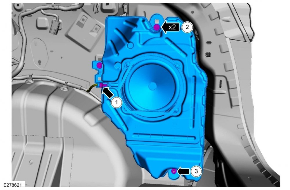
-
Tiresize.com provides dimensional comparisons and speedometer error created by different tire/rim combinations. Wheel-size.com provides OEM wheel dimensions for Edge. Wheel-size.com provides OEM wheel dimensions for Mustang. Good luck!
-
From the 2020 Edge Workshop Manual... Driveshaft Diagnosis and Testing Preliminary Inspection Verify the customer concern. Visually inspect the CV joints for obvious signs of mechanical damage. If an obvious cause for an observed or reported concern is found, correct the cause (if possible) before proceeding to the next step If the cause is not visually evident, verify the symptom and REFER to Symptom Chart: NVH. Symptom Chart Diagnostics in this manual assume a certain skill level and knowledge of Ford-specific diagnostic practices. Symptom Chart: Noise Vibration Harshness (NVH) - Edited for Edgy-ST's specified symptom Condition Possible Sources Actions Driveline vibration - occurs at cruising speeds Worn or damaged driveshaft center bearing support CHECK the insulator for damage or wear. ROTATE the driveshaft and CHECK for rough operation. INSTALL a new driveshaft as necessary. REFER to: Rear Driveshaft - 2.0L EcoBoost (177kW/240PS) – MI4 (205-01 Driveshaft, Removal and Installation). REFER to: Rear Driveshaft - 2.7L EcoBoost (238kW/324PS) (205-01 Driveshaft, Removal and Installation). Loose axle pinion flange bolts INSPECT the axle pinion flange. TIGHTEN the pinion flange bolts to specification. REFER to: Rear Driveshaft - 2.0L EcoBoost (177kW/240PS) – MI4 (205-01 Driveshaft, Removal and Installation). REFER to: Rear Driveshaft - 2.7L EcoBoost (238kW/324PS) (205-01 Driveshaft, Removal and Installation). Excessive axle pinion flange runout CARRY OUT a runout check. REPAIR as necessary. REFER to: Specifications (205-01 Driveshaft, Specifications). Driveshaft is out of balance CHECK the driveshaft for damage, missing balance weights or undercoating. CHECK the driveshaft balance. CARRY OUT a driveline vibration test. REFER to: Driveshaft Runout and Balancing (205-01 Driveshaft, General Procedures). Binding or damaged driveshaft CV -joint INSPECT the driveshaft CV -joint for wear or damage. INSTALL a new driveshaft as necessary. REFER to: Rear Driveshaft - 2.7L EcoBoost (238kW/324PS) (205-01 Driveshaft, Removal and Installation). Excessive driveshaft runout CARRY OUT a runout check. REFER to: Driveshaft Runout and Balancing (205-01 Driveshaft, General Procedures). Driveline angles out of specification CHECK for correct driveline angles. REPAIR as necessary. REFER to: Driveshaft Angle Measurement (205-01 Driveshaft, General Procedures). Center bearing bolts not properly seated REPLACE and TORQUE the center bearing bolts. REFER to: Rear Driveshaft - 2.0L EcoBoost (177kW/240PS) – MI4 (205-01 Driveshaft, Removal and Installation). REFER to: Rear Driveshaft - 2.7L EcoBoost (238kW/324PS) (205-01 Driveshaft, Removal and Installation). Rear Drive Halfshafts Diagnosis and Testing Preliminary Inspection Visually inspect the CV joints, housing, boots, and clamps for obvious signs of mechanical damage. If an obvious cause for an observed or reported concern is found, correct the cause (if possible) before proceeding to the next step If the cause is not visually evident, verify the symptom and REFER to Symptom Chart: NVH. Symptom Chart(s) Diagnostics in this manual assume a certain skill level and knowledge of Ford-specific diagnostic practices. Symptom Chart: Noise Vibration Harshness (NVH) - Edited for Edgy-ST's specified symptom Condition Action Driveline vibration - occurs at cruising speeds GO to Pinpoint Tests K & D Below are PDF download links to referenced and relevant Workshop Manual sections... Rear Driveshaft - 2.7L EcoBoost - Removal and Installation - 2020 Edge Workshop Manual.pdf Driveshaft Specifications - 2020 Edge Workshop Manual.pdf Driveshaft Runout and Balancing - General Procedures - 2020 Edge Workshop Manual.pdf Driveshaft Angle Measurement - General Procedures - 2020 Edge Workshop Manual.pdf Rear Drive Axle and Differential - Description and Operation - 2020 Edge Workshop Manual.pdf Rear Drive Axle and Differential - System Operation and Component Description - 2020 Edge Workshop Manual.pdf Rear Drive Axle and Differential - Diagnosis and Testing - Pinpoint Test K - 2020 Edge Workshop Manual.pdf Rear Drive Halfshafts - Diagnosis and Testing - Pinpoint Test D - 2020 Edge Workshop Manual.pdf Rear Halfshaft - Removal and Installation - 2020 Edge Workshop Manual.pdf Rear Drive Axle Differential Specifications - 2020 Edge Workshop Manual.pdf Differential Draining and Filling - General Procedures - 2020 Edge Workshop Manual.pdf Differential Fluid Level Check - General Procedures - 2020 Edge Workshop Manual.pdf Rear Drive Unit (RDU) Actuator Motor - Removal and Installation - 2020 Edge Workshop Manual.pdf Rear Drive Unit (RDU) Speed Sensor - Removal and Installation - 2020 Edge Workshop Manual.pdf Good luck!
-
Whats leaking and should I be worried?
Haz replied to DhaemonX's topic in 2015+ Edge & MKX Generation II
Oil leak diagnostic advice from the 2016 Edge Workshop Manual... Engine Oil Leaks NOTE: If an overnight drive is done, the fan air or road air blast can cause erroneous readings. NOTE: When diagnosing engine oil leaks, the source and location of the leak must be positively identified prior to repair. Prior to carrying out this procedure, clean the cylinder block, cylinder heads, valve covers, oil pan and flywheel/flexplate with a suitable solvent to remove all traces of oil. Engine Oil Leaks - Fluorescent Oil Additive Method NOTE: If the factory fill engine oil with dye is present, change the engine oil and the oil filter prior to using the Dye-Lite® Oil-Based Fluid Dye (164-TP33200601). Use the UV Long-Wave W/12-foot Cord & Alligator Clips (164-R3748) or Leak Tracker UV-LED Leak Detection Flashlight (164-TP8695) to carry out the following procedure for oil leak diagnosis. Add 29.6 ml (1 oz) of Dye-Lite® Oil-Based Fluid Dye (164-TP33200601) to a minimum of 0.47L (1/2 qt) and a maximum of 0.95L (1 qt) engine oil. Thoroughly premix the oil based fluid dye or it will not have enough time to reach the crankcase, oil galleries and seal surfaces during this particular 15 minute test. The additive must be added through the oil fill. Check the level on the oil level indicator to determine what amount of oil to premix. If it is in the middle of the crosshatch area or below the full mark, use 0.95L (1 qt). If it is at the full mark, use 0.47L (1/2 qt). NOTE: For best results allow the customer to drive the vehicle for a day. Run the engine for 15 minutes. Stop the engine and inspect all seal and gasket areas for leaks using the UV Leak Detector Kit. A fluoresces white area will identify the leak. For extremely small leaks, several hours may be required for the leak to appear. At the end of test, make sure the oil level is within the upper and lower oil indicator marks. Remove oil as necessary if it registers above the full mark. Leakage Points - Underhood Examine the following areas for oil leakage: Valve cover gaskets Cylinder head gaskets Oil cooler, if equipped Oil filter adapter Engine front cover Oil filter adapter and filter body Oil level indicator tube connection Oil pressure switch or oil pressure sensor Turbocharger oil tubes Leakage Points - Under Engine, With Vehicle on Hoist Examine the following areas for oil leakage: Oil pan gaskets Oil pan sealer Engine front cover gasket Crankshaft front seal Crankshaft rear oil seal Oil filter adapter and filter body Oil cooler, if equipped Turbocharger oil tubes Leakage Points - With Transmission and Flywheel/Flexplate Removed Examine the following areas for oil leakage: Crankshaft rear oil seal Rear main bearing cap parting line Flexplate mounting bolt holes (with flexplate installed) Pipe plugs at the end of oil passages Transmission fluid leak advice... Leak Check Test With the vehicle in NEUTRAL, position the vehicle on a hoist. Inspect the gasket and sealing areas for evidence of leakage. Trace the transmission fluid leak to the highest point. Clean area of suspected leak. Lower vehicle. Remove the transmission fluid fill plug. Add leak detection dye to the transmission fluid. Use 1 fl oz (30 ml) of dye solution for every 4 qt (3.8 L) of transmission fluid. Road test the vehicle for at least 1 mile with at least 1 application of the TCC . With the vehicle in NEUTRAL, position the vehicle on a hoist. If the source of the leak is obvious, repair as required. After the repair, clean the affected area. Leakage From Torque Converter Housing Add leak detection dye 1 fl oz ( 30 ml) of dye solution for every 4 qt ( 3.8 L) of transmission fluid. Leaks from the torque converter housing can originate from several locations. The paths which the transmission fluid takes to reach the bottom of the torque converter housing is shown in the illustration. The 5 following steps correspond with the numbers in the illustration. Transmission fluid leaking by the converter hub seal lip will tend to move along the drive hub and onto the back of the torque converter. Except in the case of a total seal failure, transmission fluid leakage by the lip of the seal will be deposited on the inside of the torque converter housing only, near the outside diameter of the housing. Transmission fluid leakage by the outside diameter of the torque converter impeller hub seal and the case will follow the same path that leaks by the inside diameter of the converter hub seal follow. Transmission fluid leakage from the converter cover weld or the converter-to-flexplate stud weld will appear at outside diameter of torque converter on the back face of the flexplate and in the converter housing only near the flexplate. If a converter-to-flexplate lug, lug weld or converter cover weld leak is suspected, remove the converter and pressure check. Transmission fluid leakage from the bolts inside the converter housing will flow down the back of the torque converter housing. Leakage may be from loose or missing bolts. Engine oil leaks from the rear main oil. Remove the torque converter. Using a black light, observe the torque converter housing. Inspect for evidence of dye from the pump bolts, pump seal, and torque converter hub seal. Repair as required. If the source of the leak is not evident, continue with this procedure to leak test the torque converter. Good luck! -
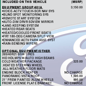
Your Edge's VIN show's it has the optional HID headlights... Good luck!
-
PDF Download links... 2016 Edge Order Guide.pdf 2016 Ford Edge Sales Brochure.pdf Good luck!
-
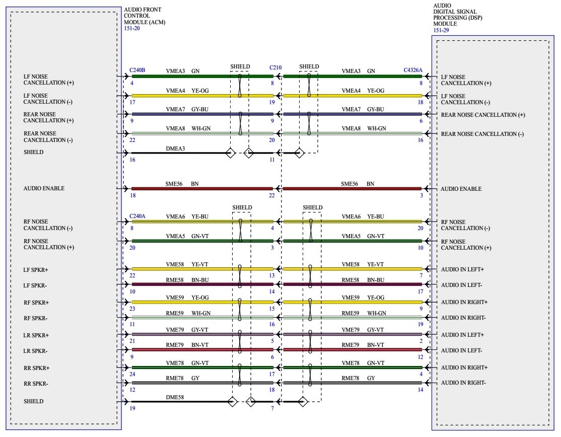
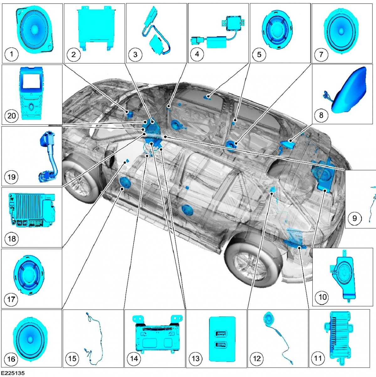
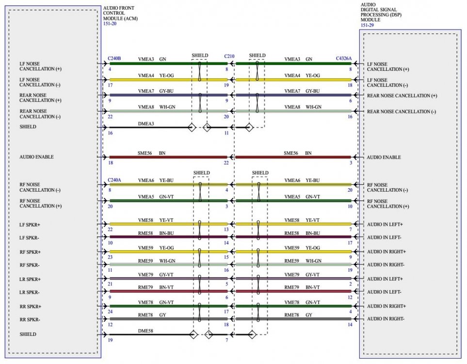
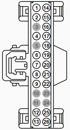
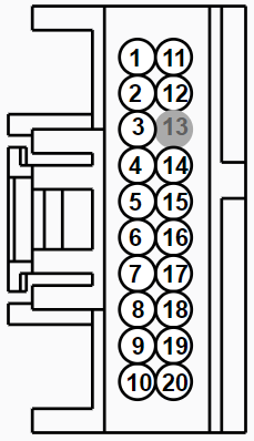
Diagnostic procedure from the 2016 Edge Workshop Manual: Pinpoint Test F... SYMPTOM: No Sound From All Speakers Refer to Wiring Diagram for schematic and connector information... Wiring & Connector & Module Document Download Links Information and Entertainment System - Wiring Diagram Pg 03 - 2016 Edge Workshop Manual.pdf Information and Entertainment System - Audio Digital Signal Processing (DSP) Module Connector C4326A Details - 2016 Edge Workshop Manual.pdf Information and Entertainment System - Audio Digital Signal Processing (DSP) Module Connector C4326A-B-C Location - 2016 Edge Workshop Manual.pdf Information and Entertainment System - Audio Front Control Module (ACM) Connector C240B Details - 2016 Edge Workshop Manual.pdf Information and Entertainment System - Audio Front Control Module (ACM) Connector C240B Location - 2016 Edge Workshop Manual.pdf Information and Entertainment System - Front Controls Interface Module (FCIM) Removal and Installation - Sony Audio System - 2016 Edge Workshop Manual.pdf Information and Entertainment System - Front Control-Display Interface Module (FCDIM) Removal and Installation - Sony Audio System - 2016 Edge Workshop Manual.pdf Information and Entertainment System - Audio Front Control Module (ACM) Removal and Installation - Sony Audio System - 2016 Edge Workshop Manual.pdf Information and Entertainment System - Audio Digital Signal Processing (DSP) Module Removal and Installation - Sony Audio System - 2016 Edge Workshop Manual.pdf Normal Operation and Fault Conditions REFER to: Information and Entertainment System - Operation and Component Description - Sony Audio System - 2016 Edge Workshop Manual.pdf. <<(Download Link) See Audio DSP Module. When the ignition status message from the BCM indicates that the engine is cranking, the ACM mutes the audio output. If the audio DSP module detects an open, short to ground, or less than 3.5 volts on the enable circuit, the speaker output will be muted for all of the speakers. A short to ground or short to voltage in the circuitry to one of the speakers may cause multiple speakers to lose sound due to the built-in overload protection feature of the audio DSP module. In this case, a speaker fault DTC sets. DTC Fault Trigger Conditions DTC Description Fault Trigger Conditions DTC Type B1142:27 Ignition Status 1: Signal Rate of Change Above Threshold Set by the ACM when an error is detected in the ignition status message from the BCM during engine start. Continuous B13FB:11 Audio Enable Line: Circuit Short To Ground Set by the audio DSP module when a short to ground is detected on the enable circuit Continuous Possible Sources Wiring, terminals, or connectors ACM Audio DSP module PINPOINT TEST F: NO SOUND FROM ALL SPEAKERS F1 VERIFY THAT THE ACM (AUDIO FRONT CONTROL MODULE) AND AUDIO DSP (AUDIO DIGITAL SIGNAL PROCESSING MODULE) MODULE PASS THE NETWORK TEST Using a diagnostic scan tool, perform the network test. Did the ACM and audio DSP module pass the network test? Yes GO to F2 No REFER to: Communications Network (418-00 Module Communications Network, Diagnosis and Testing). F2 CHECK FOR SPEAKER DIAGNOSTIC TROUBLE CODES (DTCS) Ignition ON. Using a diagnostic scan tool, perform the audio DSP module self-test. Are any speaker fault Diagnostic Trouble Codes (DTCs) present? Yes REFER to the DSP DTC Chart: DTC Chart: Audio DSP Module DTC Description Action B1045:13 Chime: Circuit Open REFER to: Instrumentation, Message Center and Warning Chimes (413-01 Instrumentation, Message Center and Warning Chimes, Diagnosis and Testing). B13FB:11 Audio Enable Line: Circuit Short To Ground GO to Pinpoint Test F B13FD:13 Chime Input 2: Circuit Open REFER to: Instrumentation, Message Center and Warning Chimes (413-01 Instrumentation, Message Center and Warning Chimes, Diagnosis and Testing). B1A01:01 Speaker #1: General Electrical Failure GO to Pinpoint Test J B1A01:11 Speaker #1: Circuit Short To Ground GO to Pinpoint Test J B1A01:12 Speaker #1: Circuit Short To Battery GO to Pinpoint Test J B1A01:13 Speaker #1: Circuit Open GO to Pinpoint Test J B1A02:01 Speaker #2: General Electrical Failure GO to Pinpoint Test H B1A02:11 Speaker #2: Circuit Short To Ground GO to Pinpoint Test H B1A02:12 Speaker #2: Circuit Short To Battery GO to Pinpoint Test H B1A02:13 Speaker #2: Circuit Open GO to Pinpoint Test H B1A03:01 Speaker #3: General Electrical Failure GO to Pinpoint Test I B1A03:11 Speaker #3: Circuit Short To Ground GO to Pinpoint Test I B1A03:12 Speaker #3: Circuit Short To Battery GO to Pinpoint Test I B1A03:13 Speaker #3: Circuit Open GO to Pinpoint Test I B1A04:01 Speaker #4: General Electrical Failure For a LHR door speaker concern, GO to Pinpoint Test O For a LHR door tweeter speaker concern, GO to Pinpoint Test P B1A04:11 Speaker #4: Circuit Short To Ground For a LHR door speaker concern, GO to Pinpoint Test O For a LHR door tweeter speaker concern, GO to Pinpoint Test P B1A04:12 Speaker #4: Circuit Short To Battery For a LHR door speaker concern, GO to Pinpoint Test O For a LHR door tweeter speaker concern, GO to Pinpoint Test P B1A04:13 Speaker #4: Circuit Open For a LHR door speaker concern, GO to Pinpoint Test O For a LHR door tweeter speaker concern, GO to Pinpoint Test P B1A05:01 Speaker #5: General Electrical Failure GO to Pinpoint Test Q B1A05:11 Speaker #5: Circuit Short To Ground GO to Pinpoint Test Q B1A05:12 Speaker #5: Circuit Short To Battery GO to Pinpoint Test Q B1A05:13 Speaker #5: Circuit Open GO to Pinpoint Test Q B1A06:01 Speaker #6: General Electrical Failure GO to Pinpoint Test K B1A06:11 Speaker #6: Circuit Short To Ground GO to Pinpoint Test K B1A06:12 Speaker #6: Circuit Short To Battery GO to Pinpoint Test K B1A06:13 Speaker #6: Circuit Open GO to Pinpoint Test K B1A07:01 Speaker #7: General Electrical Failure GO to Pinpoint Test L B1A07:11 Speaker #7: Circuit Short To Ground GO to Pinpoint Test L B1A07:12 Speaker #7: Circuit Short To Battery GO to Pinpoint Test L B1A07:13 Speaker #7: Circuit Open GO to Pinpoint Test L B1A08:01 Speaker #8: General Electrical Failure For a RHR door speaker concern, GO to Pinpoint Test M For a RHR door tweeter speaker concern, GO to Pinpoint Test N B1A08:11 Speaker #8: Circuit Short To Ground For a RHR door speaker concern, GO to Pinpoint Test M For a RHR door tweeter speaker concern, GO to Pinpoint Test N B1A08:12 Speaker #8: Circuit Short To Battery For a RHR door speaker concern, GO to Pinpoint Test M For a RHR door tweeter speaker concern, GO to Pinpoint Test N B1A08:13 Speaker #8: Circuit Open For a RHR door speaker concern, GO to Pinpoint Test M For a RHR door tweeter speaker concern, GO to Pinpoint Test N B1A09:11 Speaker #9: Circuit Short To Ground GO to Pinpoint Test R B1A09:12 Speaker #9: Circuit Short To Battery GO to Pinpoint Test R B1A09:13 Speaker #9: Circuit Open GO to Pinpoint Test R B1A10:11 Speaker #10: Circuit Short To Ground GO to Pinpoint Test R B1A10:12 Speaker #10: Circuit Short To Battery GO to Pinpoint Test R B1A10:13 Speaker #10: Circuit Open GO to Pinpoint Test R U0155:00 Lost Communication With Instrument Panel Cluster (IPC) Control Module: No Sub Type Information GO to Pinpoint Test AN U0184:00 Lost Communication With Radio: No Sub Type Information GO to Pinpoint Test AO U0237:00 Lost Communication With Digital Audio Control Module "C": No Sub Type Information GO to Pinpoint Test AP U0253:00 Lost Communication With Accessory Protocol Interface Module: No Sub Type Information GO to Pinpoint Test AR U0256:00 Lost Communication With Front Controls Interface Module "A": No Sub Type Information GO to Pinpoint Test AS U0257:00 Lost Communication With Front Control/Display Interface Module: No Sub Type Information GO to Pinpoint Test AT U0423:00 Invalid Data Received From Instrument Panel Cluster Control Module: No Sub Type Information RETRIEVE and FOLLOW Diagnostic Trouble Codes (DTCs) present in the IPC . REFER to: Instrumentation, Message Center and Warning Chimes (413-01 Instrumentation, Message Center and Warning Chimes, Diagnosis and Testing). If no Diagnostic Trouble Codes (DTCs) are present in the IPC , DIAGNOSE the observable symptom. U2014:4B Control Module Hardware: Over Temperature CLEAR the DTC . WAIT at least 10 seconds. REPEAT the self-test. If DTC U2014:4B is retrieved again, INSTALL a new audio DSP module. REFER to: Audio Digital Signal Processing (DSP) Module (415-00C Information and Entertainment System - General Information - Vehicles With: Sony Audio System, Removal and Installation). U2014:96 Control Module Hardware: Component Internal Failure CLEAR the DTC . WAIT at least 10 seconds. REPEAT the self-test. If DTC U2014:96 is retrieved again, INSTALL a new audio DSP module. REFER to: Audio Digital Signal Processing (DSP) Module (415-00C Information and Entertainment System - General Information - Vehicles With: Sony Audio System, Removal and Installation). U201A:51 Control Module Main Calibration Data: Not Programmed This DTC sets due to incomplete or incorrect PMI procedures. CHECK the vehicle service history for recent service actions related to the audio DSP module. If there have been recent service actions with the audio DSP module, INSTALL As-Built data from Professional Technician Society (PTS), following the diagnostic scan tool instructions under Module Programming>As-Built. REFER to: Module Configuration - System Operation and Component Description (418-01 Module Configuration, Description and Operation). If there have been no recent service actions, INSTALL a new audio DSP module to correct the failure to retain configuration data. REFER to: Audio Digital Signal Processing (DSP) Module (415-00C Information and Entertainment System - General Information - Vehicles With: Sony Audio System, Removal and Installation). U2100:00 Initial Configuration Not Complete: No Sub Type Information This DTC sets due to incomplete or incorrect PMI procedures. CHECK the vehicle service history for recent service actions related to the audio DSP module. If there have been recent service actions with the audio DSP module, INSTALL As-Built data from Professional Technician Society (PTS), following the diagnostic scan tool instructions under Module Programming>As-Built. REFER to: Module Configuration - System Operation and Component Description (418-01 Module Configuration, Description and Operation). If there have been no recent service actions, INSTALL a new audio DSP module to correct the failure to retain configuration data. REFER to: Audio Digital Signal Processing (DSP) Module (415-00C Information and Entertainment System - General Information - Vehicles With: Sony Audio System, Removal and Installation). U2101:00 Control Module Configuration Incompatible: No Sub Type Information This DTC sets due to incomplete or incorrect PMI procedures. CHECK the vehicle service history for recent service actions related to the audio DSP module. If there have been recent service actions with the audio DSP module, INSTALL As-Built data from Professional Technician Society (PTS), following the diagnostic scan tool instructions under Module Programming>As-Built. REFER to: Module Configuration - System Operation and Component Description (418-01 Module Configuration, Description and Operation). If there have been no recent service actions, INSTALL a new audio DSP module to correct the failure to retain configuration data. REFER to: Audio Digital Signal Processing (DSP) Module (415-00C Information and Entertainment System - General Information - Vehicles With: Sony Audio System, Removal and Installation). U3000:41 Control Module: General Checksum Failure CLEAR the DTC . WAIT at least 10 seconds. REPEAT the self-test. If DTC U3000:41 is retrieved again, INSTALL a new audio DSP module. REFER to: Audio Digital Signal Processing (DSP) Module (415-00C Information and Entertainment System - General Information - Vehicles With: Sony Audio System, Removal and Installation). U3003:16 Battery Voltage: Circuit Voltage Below Threshold GO to Pinpoint Test AU U3003:17 Battery Voltage: Circuit Voltage Above Threshold GO to Pinpoint Test AV No GO to F3 F3 CHECK THE ENABLE CIRCUIT FUNCTIONALITY BY CHECKING THE AUDIBLE PROMPT FUNCTIONALITY Operate the audio system in AM / FM mode. Operate the VOICE steering wheel switch and listen for the SYNC® audible prompt. Does the SYNC® system produce an audible prompt correctly; indicating voice recognition mode has been entered? Yes GO to F4 No GO to F5 F4 CHECK FOR AN AUDIO SIGNAL TO THE AUDIO DSP (AUDIO DIGITAL SIGNAL PROCESSING MODULE) MODULE NOTICE: This pinpoint test step directs testing circuits using a back-probe method. Use the special back-probe tool POM6411. Do not force test leads or other probes into connectors. Adequate care must be exercised to avoid connector terminal damage, while ensuring that good electrical contact is made with the circuit or terminal. Failure to follow these instructions may cause damage to wiring, terminals, or connectors, and may cause subsequent electrical faults. Ignition ON. Operate the audio system in AM / FM mode. While back-probing audio DSP module C4326A, measure the AC voltage. Positive Lead Measurement / Action Negative Lead C4326A-7 C4326A-17 Is a fluctuating AC voltage present? Yes GO to F10 No GO to F9 F5 CHECK THE AUDIO DSP (AUDIO DIGITAL SIGNAL PROCESSING MODULE) MODULE ENABLE CIRCUIT FOR CORRECT VOLTAGE NOTICE: This pinpoint test step directs testing circuits using a back-probe method. Use the special back-probe tool POM6411. Do not force test leads or other probes into connectors. Adequate care must be exercised to avoid connector terminal damage, while ensuring that good electrical contact is made with the circuit or terminal. Failure to follow these instructions may cause damage to wiring, terminals, or connectors, and may cause subsequent electrical faults. While back-probing audio DSP module C4326A, measure the DC voltage. Positive Lead Measurement / Action Negative Lead C4326A-3 Ground Is the voltage between 3.5 and 8.5 volts? Yes GO to F10 No GO to F6 F6 CHECK THE AUDIO DSP (AUDIO DIGITAL SIGNAL PROCESSING MODULE) MODULE ENABLE CIRCUIT FOR A SHORT TO VOLTAGE Ignition OFF. Disconnect: Audio DSP Module C4326A >>> Disconnect: ACM C240B>>> Ignition ON. Measure: Positive Lead Measurement / Action Negative Lead C4326A-3 Ground Is any voltage present? Yes REPAIR the circuit. No GO to F7 F7 CHECK THE AUDIO DSP (AUDIO DIGITAL SIGNAL PROCESSING MODULE) MODULE ENABLE CIRCUIT FOR A SHORT TO GROUND Ignition OFF. Measure: Positive Lead Measurement / Action Negative Lead C4326A-3 Ground Is the resistance greater than 10,000 ohms? Yes GO to F8 No REPAIR the circuit. F8 CHECK THE AUDIO DSP (AUDIO DIGITAL SIGNAL PROCESSING MODULE) MODULE ENABLE CIRCUIT FOR AN OPEN Measure: Measurement / Action Negative Lead C4326A-3 C240B-18 Is the resistance less than 3 ohms? Yes GO to F9 No REPAIR the circuit. F9 CHECK FOR CORRECT ACM (AUDIO FRONT CONTROL MODULE) OPERATION Ignition OFF. Disconnect and inspect all the ACM connectors and related in-line connectors. Repair: corrosion (clean module pins or install new connectors or terminals) damaged or bent pins (install new terminals or pins) pushed-out pins (install new pins as necessary) Reconnect the ACM connectors and related in-line connectors. Make sure they seat and latch correctly. Operate the system and determine if the concern is still present. Is the concern still present? Yes CHECK OASIS for any applicable Technical Service Bulletins (TSBs). If a TSB exists for this concern, discontinue this test and follow TSB instructions. If no Technical Service Bulletins (TSBs) address this concern, INSTALL a new ACM . REFER to: Audio Front Control Module (ACM) (415-00C Information and Entertainment System - General Information - Vehicles With: Sony Audio System, Removal and Installation). No The system is operating correctly at this time. The concern may have been caused by module connections. ADDRESS the root cause of any connector or pin issues. F10 CHECK FOR CORRECT AUDIO DSP (AUDIO DIGITAL SIGNAL PROCESSING MODULE) MODULE OPERATION Ignition OFF. Disconnect and inspect all the audio DSP module connectors and related in-line connectors. Repair: corrosion (clean module pins or install new connectors or terminals) damaged or bent pins (install new terminals or pins) pushed-out pins (install new pins as necessary) Reconnect the audio DSP module connectors and related in-line connectors. Make sure they seat and latch correctly. Operate the system and determine if the concern is still present. Is the concern still present? Yes CHECK OASIS for any applicable Technical Service Bulletins (TSBs). If a TSB exists for this concern, discontinue this test and follow TSB instructions. If no Technical Service Bulletins (TSBs) address this concern, INSTALL a new audio DSP module. REFER to: Audio Digital Signal Processing (DSP) Module (415-00C Information and Entertainment System - General Information - Vehicles With: Sony Audio System, Removal and Installation). No The system is operating correctly at this time. The concern may have been caused by module connections. ADDRESS the root cause of any connector or pin issues. Information and Entertainment System - Component Location - Sony Audio System Below: Placing your cursor/pointer over acronyms provides popup descriptor of that acronym :Below Item Description 1 Instrument panel speaker 2 FDIM 3 SYNC® microphone 4 ANC microphones (located in headliner) 5 Door tweeter speaker 7 Door speaker 8 AM / FM / GPS /satellite radio antenna 9 GPS /satellite radio splitter 10 Subwoofer 11 Audio DSP module 12 D-pillar speaker 13 USB hub 14 ACM 15 USB cable 16 Door speaker 17 Door tweeter 18 APIM 19 Low Voltage Differential Signaling (LVDS) cable 20 FCIM If you require additional Connector or Pinpoint Test information, just let me know and I will provide. Good luck!


-
Forgive my unnecessarily harsh choice of words that did not provide you the "Welcome to the Forum" that you deserve. The 'Bezel Diagnostics' procedure for 2016 Edge with Sony audio is slightly different from the previously offered 2022 Edge version. Give this document a look and a try, while I work toward providing you additional information... Information and Entertainment System - Bezel Diagnostics - Sony Audio System - 2016 Edge Workshop Manual.pdf Good luck!
-
Because you failed to mention your Edge's model year, trim level, and radio type, below are PDF download links to Audio Control Module (ACM)/Bezel Diagnostic procedures for GEN I, GEN I +, and GEN II Edge models... GEN I: Audio Control Module (ACM) Self-Diagnostic Mode - 2009 Edge Workshop Manual.pdf GEN I +: Bezel Diagnostics Procedure - 2014 Edge Workshop Manual.pdf GEN II: Bezel Diagnostics Procedure - 2022 Edge Workshop Manual.pdf See if your Edge's audio system will allow you to access any of the described functions, and then report back on the outcome -- along with your Edge's model year, trim level, and radio type. Getting your Edge's electronic modules scanned for Diagnostic Trouble Codes (DTCs), perhaps at your local national brand auto parts store, may also reveal useful information related to the radio problem. Good luck!
-
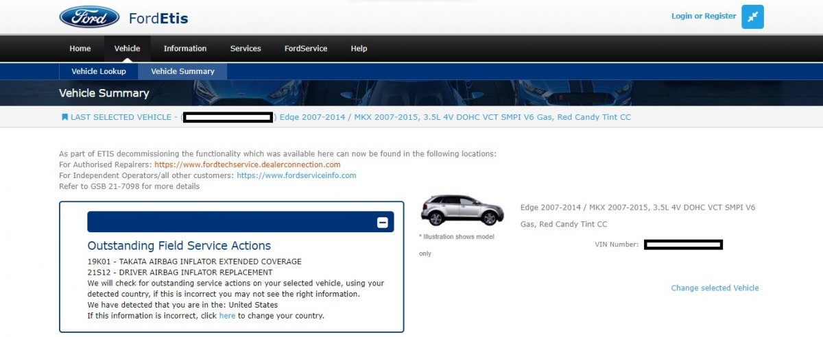
Adding my welcome to you, also! You may wish to input your Edge's VIN into this Ford website in order to determine if there are any unfulfilled Field Service Actions on the new-to-you Edge... If any Outstanding Field Service Actions are shown for your Edge, scan through the Recalls, TSBs & Warranty forum for information. If you cannot find any reference on the unfulfilled Field Service Action shown for your Edge, offer a reply here and I will obtain information for you, or, contact your local Ford dealer. Good luck!

-
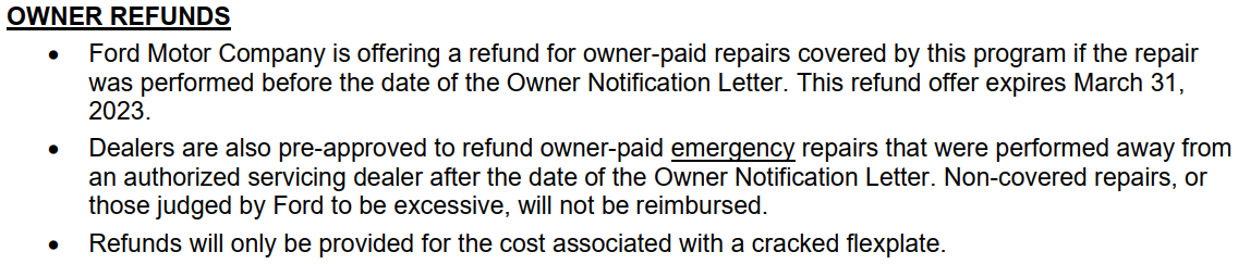
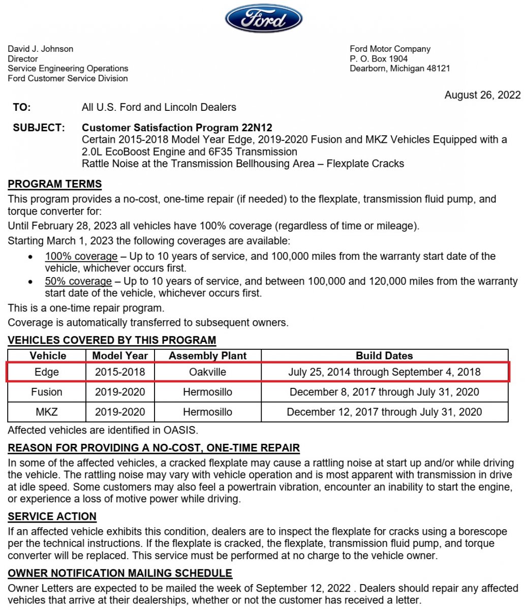
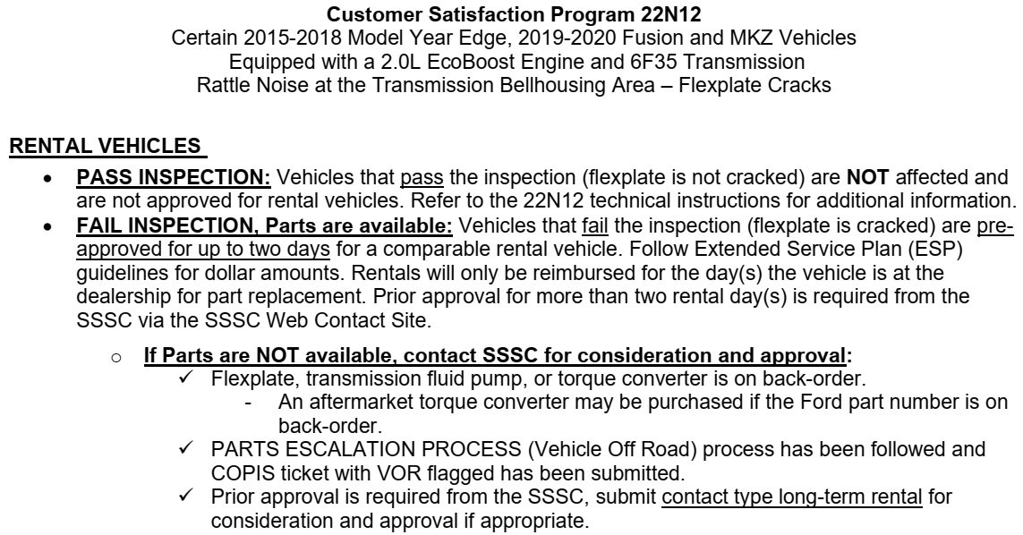
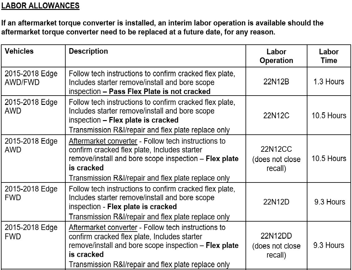
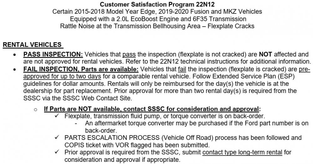
Customer Satisfaction 22N12- Flex Plate Crack on 2.0
Haz replied to All Hat No Cattle's topic in Recalls, TSBs & Warranty
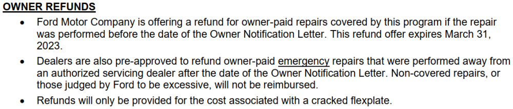
Consistent with WxManChris' cracked flexplate photo above, are these example photos (with arrows added) from the Technical Info document linked in my earlier post, and below... Customer Satisfaction Program 22N12 - Technical Info.pdf Good luck!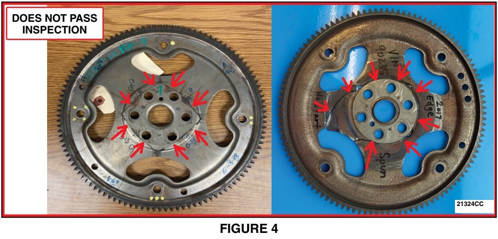
-
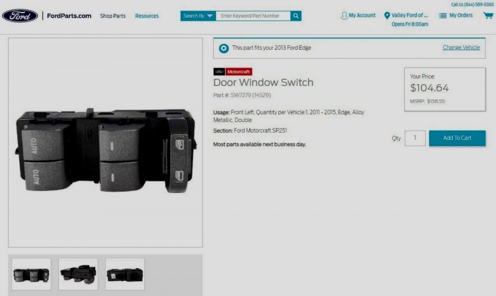
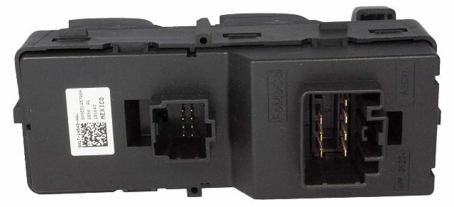
It may be a longshot solution, but because it precedes replacing the switch assembly in the Pinpoint H test procedure -- and it could save you over $100 -- you may want to employ someone to help you perform the De-inititialization procedure on the left hand Window Motor, followed by the Initialization procedure, as described in the Window Motor Initialization Procedure - 2013 Edge-MKX Workshop Manual document, which is the following... De-Initialization procedure NOTE: The front window motor must be reset to its original factory settings first, then carry out the following de-initialization procedure. Turn the ignition key ON. Operate the window control switch in one-touch mode and remove power from the window motor while the window is moving by one of the following methods: Disconnect the vehicle battery cable while the window is moving. Disconnect the window motor connector while the window is moving. Remove the LH or RH front window motor fuse while the window is moving. This will de-initialize the window motor and reset the window motor to its original factory settings. Carry out the initialization procedure to turn the one-touch-up feature on. Initialization procedure WARNING: Keep objects and body parts clear of the glass panel when carrying out the initialization procedure. During the initialization procedure, the glass panel closes with high force and cannot detect objects in its path. Failure to follow this instruction may result in serious personal injury. NOTE: The front window must be in the full OPEN position for this procedure to operate correctly. NOTE: If the initialization procedure is only partially completed, the front window motor will remain un-initialized and will operate only in proportional up/down and one-touch-down modes. Turn the ignition key ON. Activate and hold the window control switch in the UP position at the second detent until the window glass stalls for 2 seconds into the glass top run and release the switch. Activate and hold the window control switch in the DOWN position at the second detent until the window glass stalls for 2 seconds at the bottom of its travel and release the switch. Test for correct window operation by carrying out the one-touch-up and one-touch-down features. As previously mentioned, this may or may not resolve the problem, but at least you'll know before investing in a replacement switch assembly. And finally, connecting a continuity tester/test light tool across the switch assembly's two connector receptacles #7 pins, and actuating the left hand front window switch to the Auto/second-detent positions for Up and for Down, should confirm whether your Edge's current window switch assembly is good or faulty. Good luck!
-
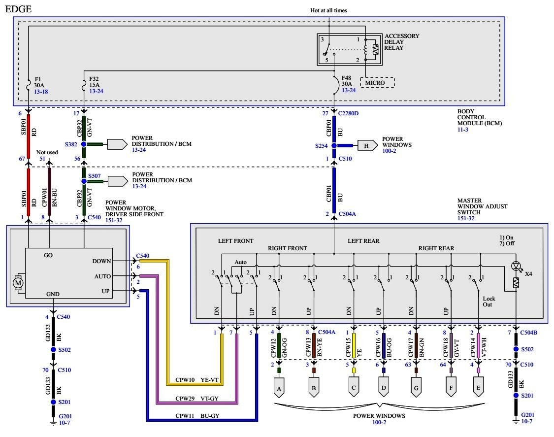
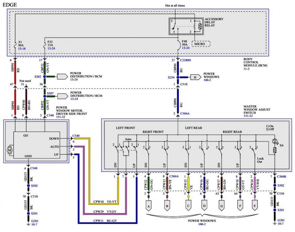
The short answer is yes, the front left hand window switch has separate contacts for Auto Up and Auto Down, so one direction could Auto function when the other direction does not Auto function... From the 2013 Edge/MKX Workshop Manual... Principles of Operation LH Front Power Window Control — Edge The one-touch up/down features are identical to the MKX LH front window. LH and RH Front Power Window Control — MKX The LH and RH front window motors contain integral electronics which must be initialized whenever a new window motor has been installed. Initialization is required to learn both the full UP and full DOWN positions and the profile of the glass as it travels through the glass channel. Once initialized, obstacle detection is enabled. When mechanical repairs have been carried out on either front window regulator or glass run, the applicable front window motor must be de-initialized, and then initialized. Both the LH and RH front window control switches send 3 separate signals to the front window motors: up, down and auto. The front window control switches provide a 12-volt signal to the front window motor to request an up or down operation. When auto up or auto down is requested, the front window control switches provide a 12-volt signal on the up or down line and a ground signal on the auto line simultaneously. The up, down and auto feeds to the front window motors are all low current. The LH and RH front window motors operate with the ignition in the RUN or ACC positions, or when the accessory delay relay is active. The high current required to move the front windows are supplied through the B+ and motor ground input. When the LH or RH front window motor is operating in auto up or auto down mode, movement of the front window can be stopped by pressing the switch to any position (UP, DOWN, auto UP, auto DOWN). The front window control switches must be released before the window can move again. The LH and RH front window motors have a security override feature. If an obstacle has been detected in the window opening as the window glass is moving upward, the window motor automatically reverses direction and moves the glass toward the fully OPEN position (in both manual up and one-touch up modes). This is known as bounce-back. Once the window motor stops the glass at its bounce-back position, and within 2 seconds the switch is released, then held in the auto UP position, the window motor moves the glass up with no bounce-back protection (security override). If the switch is released before the window glass reaches the fully CLOSED position, the window motor stops with bounce-back automatically enabled for the next window up movement. If the ignition is turned to OFF or START (without delayed accessory), the window motor stops. The only exception is when an obstacle is detected in the window opening while delayed accessory power is not present. In this case the window motor bounces back, then stops. Ice, contaminant buildup and environmentally induced tight spots in the front window seals are all possible conditions that can activate the bounce-back feature. If an obstruction occurs between 4 mm (0.15 in) and 200 mm (7.87 in) of window opening, the bounce-back position is 250 mm (9.84 in) of window opening. If an obstruction occurs at a position more than 200 mm (7.87 in) of window opening, the bounce-back position is 50 mm (1.96 in) below where the obstruction occurred. The LH and RH front window control switches have illumination and illumination ground inputs, which illuminate the switch when the headlamp switch is turned to the PARK or ON position (the AUTOLAMP position may also energize this input). These switch inputs do not directly affect operation of the front windows. The front window control switches use the delayed accessory power input, which is transferred to the up or down outputs when the corresponding switch contact is closed. The front window control switches are grounded to the chassis through the main switch ground input, which is transferred to the auto output when the corresponding front window control switch contact is closed. If the delayed accessory feed to the front window control switch is missing, the window cannot function. If the main ground signal is missing, the auto functions are inoperative and the window may also be inoperative. If there is an open in the LH or RH front window control switch or the associated wiring, the related function becomes inoperative. If the up contact of the switch or the associated wiring develops an open circuit, the front window only operates in the down direction, or in the one-touch down mode. If the down contact of the switch or the associated wiring develops an open circuit, the window only operates in the up direction or in the one-touch up mode. If the auto contact of the switch or the associated wiring develops an open circuit, the window only moves manually up or down. A new LH or RH front window motor cannot operate in one-touch up or one-touch down mode, and the bounce-back feature is disabled prior to initialization. If the switch is actuated to the auto UP or auto DOWN position and released, window movement stops when the up or down contact in the front window control switch is released. If the front window motor is removed from the window regulator drum housing, or if a new front window motor is installed, it must be initialized. Refer to Window Motor Initialization. Once initialized, the front window motors soft stall into the lower positions. If the front window does not seal completely in the full UP position (very small gaps/non bounce-back events only), the front window switch can be actuated to the proportional UP position and the front window energizes for a fraction of a second to fully seal and this new position is learned. Symptom Chart Condition Possible Sources Action The one-touch up/down feature is inoperative LH front power window motor not initialized Battery power was lost while LH front power window motor was operating Wiring, terminals or connectors Window control switch Power window motor GO to Pinpoint Test H. Pinpoint Test H: The One-Touch Up/Down Feature is Inoperative Refer to Wiring Diagrams, Power Windows for schematic and connector information. NOTE: De-initialize, then initialize the front window motor when any of the following occur: the LH or RH (MKX) or LH (Edge) front window motor is removed from the window regulator drum housing a new window regulator and/or motor is installed a new window glass is installed a new top run is installed any operation in which grease or lubricants are applied to the window regulator or glass run NOTE: A new front window motor cannot operate in one-touch up or one-touch down mode until initialized. Refer to Window Motor Initialization in this section. Normal Operation When the LH or RH (MKX) or LH (Edge) front window control switch is pressed or pulled to the second detent position (AUTO), the LH/RH front window control switch provides a ground signal to the LH or RH front window motor to request the one-touch up/down operation. This pinpoint test is intended to diagnose the following: LH or RH front power window motor not initialized Battery power was lost while LH or RH front power window motor was operating Wiring, terminals or connectors Window control switch Power window motor PINPOINT TEST H : THE ONE-TOUCH UP/DOWN FEATURE IS INOPERATIVE NOTICE: Use the correct probe adapter(s) from the Flex Probe Kit when making measurements. Failure to use the correct probe adapter(s) may damage the connector. H1 CHECK FOR POWER (B+) LOSS DURING LH OR RH FRONT WINDOW OPERATION Verify if power (B+) was lost during LH or RH front window operation. Was power (B+) lost while LH or RH front window was in operation? Yes RAISE the LH or RH front window to the fully CLOSED position. VERIFY the window glass stalls into the upper header seal. The front window should function normally. TEST the system for normal operation. No GO to H2. H2 DE-INITIALIZE, THEN INITIALIZE THE FRONT MOTOR De-initialize the front window motor, then carry out the front window motor initialization procedure. Refer to Window Motor Initialization attached below. Is the one-touch down feature operating correctly? Yes The system is operating normally at this time. The front window motor lost initialization. No For LH window, GO to H3. For RH window (MKX only), GO to H5. H3 CHECK THE LH FRONT WINDOW CONTROL SWITCH Ignition OFF. Disconnect: LH Front Window Control Switch from harness connectors C504A and C504B. Carry out the LH front window control switch component test. To assess Auto window control switch function, connect contacts of Continuity Tester/Test Light to Pin 7 of switch assembly C504A receptacle and to Pin 7 of the C504B receptacle. Operate the front left hand switch handle to the second detent Auto position in the Window Up direction and in the Window Down direction, noting if the light illuminates in one or both directions of Auto Window travel. Did the LH front window control switch pass the component test? Yes GO to H4. No INSTALL a new LH front window control switch. REFER to Window Control Switch. TEST the system for normal operation. Subsequent Pinpoint Test Steps will be provided, if required. Additional Workshop Manual documents, as PDF download links... Power Window & Master Window Adjust Switch Wiring Diagram - 2013 Edge Workshop Manual.pdf Master Window Adjust Switch - Connector C504A Details - 2013 Edge Workshop Manual.pdf Master Window Adjust Switch - Connector C504B Details - 2013 Edge Workshop Manual.pdf Window Motor Initialization Procedure - 2013 Edge-MKX Workshop Manual.pdf Window Control Switch - Removal and Installation - 2013 Edge-MKX Workshop Manual.pdf Front Window Switch Removal-Replacement - Ford Edge Lincoln MKX ( YouTube Instructional Video) Good luck!
-
One more document which, hopefully, will be unneeded by you... Instrumentation, Message Center and Warning Chimes - Diagnosis and Testing - 2007 Edge Workshop Manual.pdf Good luck!
-
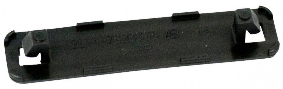
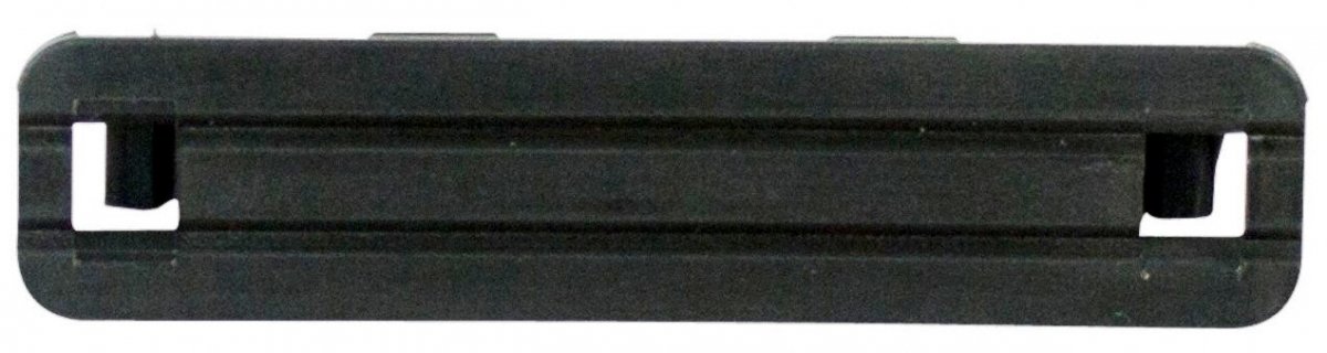
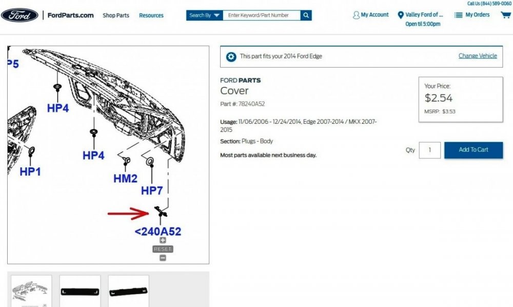
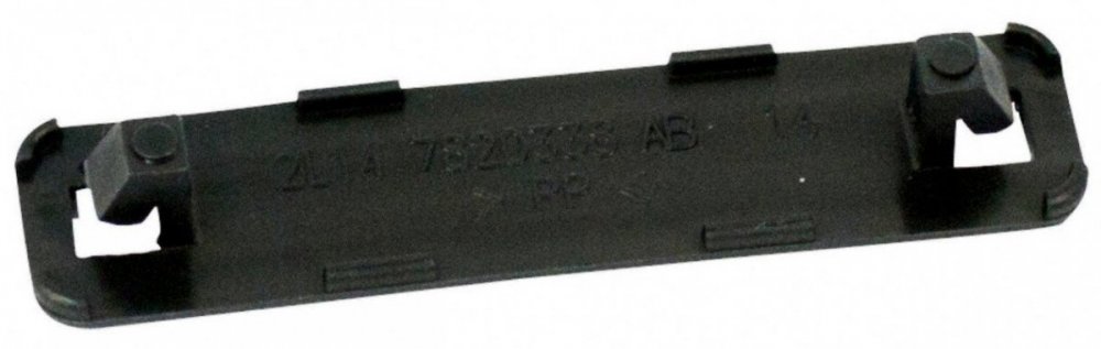
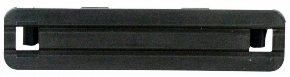
Ford's online parts site lists the black plastic strips, which are also in place on the liftgate of our 2015 MKX, but the site offers no comparable covers for side door drain holes... For what they are, the one-piece design is surprisingly elegant, with retaining ears that facilitate quick assembly-line installation and also provide slits of openess when in place... The cover's backside includes eight molded lugs that stand the installed cover off the liftgate sheet metal and allow water & air flow through the liftgate drain holes... Due to the cover's design, and the fact that replacements being sold on FordParts.com, I expect the cover is intended to remain in place after the vehicle is delivered. Below is a PDF download link to the 2014 Edge Pre-Delivery Inspection (PDI) checklist showing tasks the Service technician must complete toward the vehicle being ready for its new owner. 2014 Edge Pre-Delivery Service Record.pdf While removing external & internal covers is mentioned under 'Appearance' in the document, these are typically plastic films and overlays that protect trim and upholstery during the assembly process and shipment to the dealer. Good luck!
-
The gauge cluster symptoms are indicative of an inter-module communications fault that is often the result of low-voltage conditions caused by a failing/failed battery. Those symptoms can also be caused by wiring/connector/module faults, which require the determination you've already shown by finding the broken bare wire in the harness. The quickest-easiest check is on the battery, per ebank's advice. If the battery tests 'good' at your local big-box parts store, I will provide you wiring diagrams, connector details, and diagnostic & testing procedures to dig deeper than you already have. Getting a scanner on your Edge to assess what Diagnostic Trouble Codes (DTCs) are stored in various modules will provide a valuable path toward identifying and correcting the problem. While you are waiting on battery-test results, and to enable you to assess the bare wire's function, below as PDF download links are Powertrain Control Module (PCM) wiring diagrams and connector details... Electronic Engine Controls - 3.5L - Wiring Diagram Pg 1 - 2007 Edge Workshop Manual.pdf Electronic Engine Controls - 3.5L - Wiring Diagram Pg 2 - 2007 Edge Workshop Manual.pdf Electronic Engine Controls - 3.5L - Wiring Diagram Pg 3 - 2007 Edge Workshop Manual.pdf Electronic Engine Controls - 3.5L - Wiring Diagram Pg 4 - 2007 Edge Workshop Manual.pdf Electronic Engine Controls - 3.5L - Wiring Diagram Pg 5 - 2007 Edge Workshop Manual.pdf Electronic Engine Controls - 3.5L - Wiring Diagram Pg 6 - 2007 Edge Workshop Manual.pdf Electronic Engine Controls - 3.5L - Wiring Diagram Pg 7 - 2007 Edge Workshop Manual.pdf Electronic Engine Controls - 3.5L - Wiring Diagram Pg 8 - 2007 Edge Workshop Manual.pdf Electronic Engine Controls - 3.5L - Wiring Diagram Pg 9 - 2007 Edge Workshop Manual.pdf Electronic Engine Controls - 3.5L - Wiring Diagram Pg 10 - 2007 Edge Workshop Manual.pdf Electronic Engine Controls - 3.5L - Wiring Diagram Pg 11 - 2007 Edge Workshop Manual.pdf Electronic Engine Controls - 3.5L - Wiring Diagram Pg 12 - 2007 Edge Workshop Manual.pdf Powertrain Control Module (PCM) - Connector C175B Details - 2007 Edge Workshop Manual.pdf Powertrain Control Module (PCM) - Connector C175E Details - 2007 Edge Workshop Manual.pdf Powertrain Control Module (PCM) - Connector C175T Details - 2007 Edge Workshop Manual.pdf Powertrain Control Module (PCM) - Connector C175B-E-T Location - 2007 Edge Workshop Manual.pdf Powertrain Control Module (PCM) - Removal and Installation - 2007 Edge Workshop Manual.pdf Good luck!
-
Customer Satisfaction 22N12- Flex Plate Crack on 2.0
Haz replied to All Hat No Cattle's topic in Recalls, TSBs & Warranty
-
From the 2014 Edge Workshop Manual, as a PDF download link... Front Fender Removal and Installation - 2014 Edge Workshop Manual.pdf Good luck!
-
Relating to installation of a new battery and the Battery Monitoring System (BMS), from the 2011 Edge Workshop Manual... Carry out the Battery Monitoring System (BMS) Reset using the scan tool after the battery is connected. If the BMS Reset is not carried out, it takes approximately 8 hours for the Body Control Module (BCM) to learn the new battery state of charge. During this 8 hour period, the vehicle must be undisturbed, with no doors opened or keyless entry button presses. If the vehicle is used before the BCM is allowed to learn the new battery state of charge, engine off load shedding can still occur and a message may be displayed. Good luck!
-
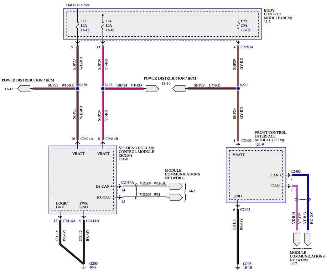
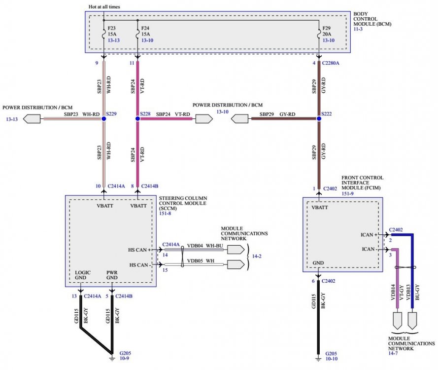
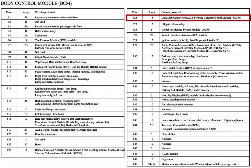
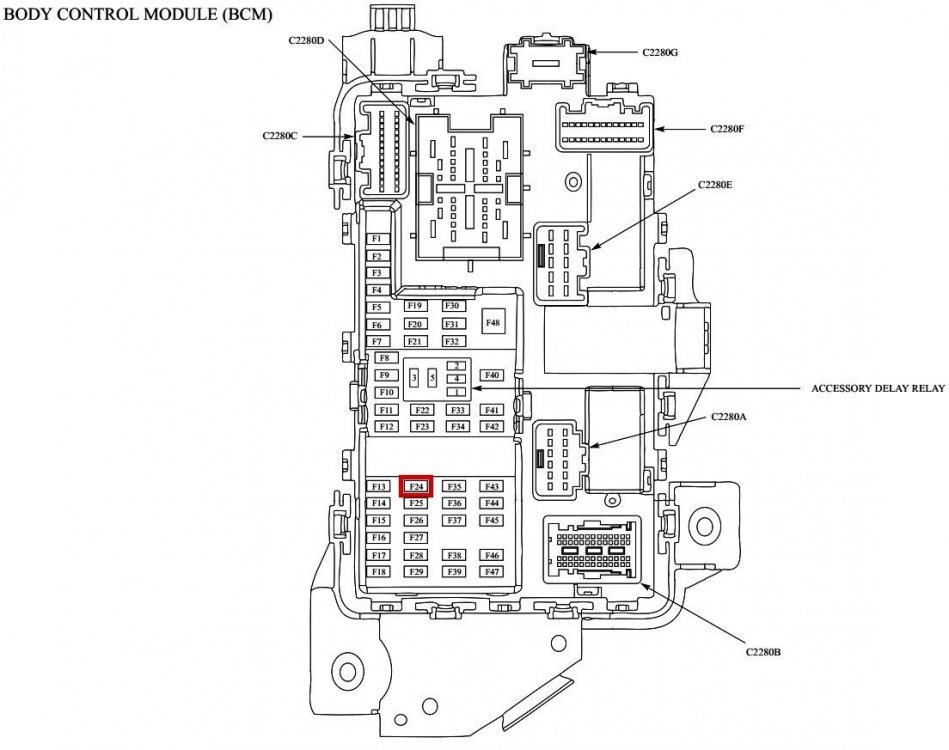
From the 2011 Edge Workshop Manual... Steering Wheel Controls [Message Center & Entertainment context description] The steering wheel controls are mounted directly to the steering wheel and wired to the Steering Column Control Module (SCCM) . Depending on what features the vehicle is equipped with, the SCCM sends messages via the High Speed Controller Area Network (HS-CAN) to the PCM (cruise control) and the Instrument Panel Cluster (IPC) (message center and entertainment system). The IPC receives the SCCM entertainment system messages via the HS-CAN and then sends them to the applicable entertainment system module(s) along the Infotainment Controller Area Network (I-CAN) . Steering Wheel Controls [Audio context description] The steering wheel controls consist of a series of resistors. Each steering wheel control switch function corresponds with a specific resistance value within the switch. When a switch is pressed, the Steering Column Control Module (SCCM) monitors the change in reference voltage to determine the requested function. The SCCM communicates the switch inputs in a message to the IPC over the HS-CAN . The IPC gateways the message to the ACM and other audio modules over the I-CAN . For Edge base and premium audio systems without SYNC®, the FCDIM serves as the infotainment display. The 5-way RH steering wheel switch controls and navigates the menus in the FCDIM . Steering Wheel Controls wiring diagram Steering Column Control Module (SCCM) Wiring Diagram Per the SCCM wiring diagram and the BCM fuse/circuits chart, fuse F24 is associated with the SCCM, so take a look at the condition of F24 in the same way you did F23. Do you have access to a scanner or a laptop with Forscan, or a phone with Forscan Lite, and an OBDII-compatible Data Link connector, in order to check your Edge for Diagnostic Trouble Codes (DTCs) that may identify current or past issues caused by the failing/failed battery? A scanner or Forscan-equivalent device could also be used to evaluate the functioning of the steering wheel switches in real-time. Good luck!

-
Customer Satisfaction 22N12- Flex Plate Crack on 2.0
Haz replied to All Hat No Cattle's topic in Recalls, TSBs & Warranty
Additional info... Technical Information document download link... Customer Satisfaction Program 22N12 - Technical Info.pdf Good luck!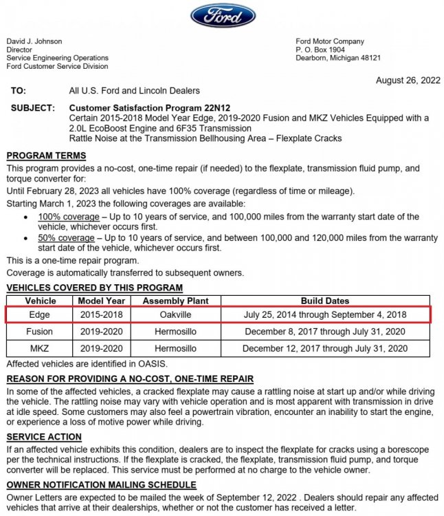

-
Below as PDF download links are PCM-related sections of the 2007 Edge Workshop Manual... Electronic Engine Controls - Description and Operation - 2007 Edge Workshop Manual.pdf POWERTRAIN CONTROL MODULE (PCM) - Removal and Installation - 2007 Edge Workshop Manual.pdf POWERTRAIN CONTROL MODULE (PCM) - Connector C175B Details - 2007 Edge Workshop Manual.pdf POWERTRAIN CONTROL MODULE (PCM) - Connector C175E Details - 2007 Edge Workshop Manual.pdf POWERTRAIN CONTROL MODULE (PCM) - Connector C175T Details - 2007 Edge Workshop Manual.pdf POWERTRAIN CONTROL MODULE (PCM) - Connectors C175B-C175E-C175T Location Illustration - 2007 Edge Workshop Manual.pdf Engine Controls Wiring Diagram 1 - 2007 Edge Workshop Manual.pdf Engine Controls Wiring Diagram 2 - 2007 Edge Workshop Manual.pdf Engine Controls Wiring Diagram 3 - 2007 Edge Workshop Manual.pdf Engine Controls Wiring Diagram 4 - 2007 Edge Workshop Manual.pdf Engine Controls Wiring Diagram 5 - 2007 Edge Workshop Manual.pdf Engine Controls Wiring Diagram 6 - 2007 Edge Workshop Manual.pdf Engine Controls Wiring Diagram 7 - 2007 Edge Workshop Manual.pdf Engine Controls Wiring Diagram 8 - 2007 Edge Workshop Manual.pdf Engine Controls Wiring Diagram 9 - 2007 Edge Workshop Manual.pdf Engine Controls Wiring Diagram 10 - 2007 Edge Workshop Manual.pdf Engine Controls Wiring Diagram 11 - 2007 Edge Workshop Manual.pdf Engine Controls Wiring Diagram 12 - 2007 Edge Workshop Manual.pdf Good luck!
-
Forum member Bill Trammell offers many useful water pump videos on his MACT Ford Edge YouTube channel. Good luck!
-
Three instances of 'PVC' corrected, though modifying the document seems nearly as egregious as modifying a PCV System. Good luck!