Haz
-
Posts
1,468 -
Joined
-
Last visited
-
Days Won
393
Everything posted by Haz
-
Removing Side Roof Panels?
Haz replied to TonyP's topic in Glass, Lenses, Lighting, Mirrors, Sunroof (BAMR), Wipers
Not sure if your insurance company funded the windshield replacement, but at this point, the front trim and the rear driver's side trim panels are vulnerable to the same loss your Edge has already suffered. Based upon costs quoted above from my earlier post, I'd suggest contacting your insurance company to see what they will cover and what your deductible, if any, will be. If your insurance company paid for the recent windshield replacement, they may have a customer satisfaction feature that may cover the side panel replacement, and then the insurance company would pursue cost recovery from Safelite, without you needing to be concerned about it. Based on your description and your photo, the missing trim panel was -- and all the still-present (for now) trim panels are -- retained only by the original plastic clips, with no urethane adhesive used at the factory. The previously posted 2016 Edge Workshop Manual sections covering roof trim panels describe removal and re-use is possible for trim panels not originally installed with urethane adhesive. For you, that's favorable, since it means those trim panels now remaining in place can be removed and reinstalled using new clips and urethane adhesive to ensure they are not eventually blown off like the now-missing panel. It's worth noting that the Workshop Manual section on Roof Trim Panel Removal and Installation was revised in late January 2017, presumably to include factory installation using urethane adhesive, whenever that revised factory procedure was implemented. When speaking with your Insurance company, it may be worth asking if they would pay for the remaining panels to be reinstalled using urethane adhesive, in order to avoid any future claims for subsequent trim panel loss. Even if they won't cover it, perhaps your dealer or other repair facility will discount their pricing based upon the totality of the job. For the sake of readability, I will include an edited Side Trim Panel procedure from the 2015 Edge Workshop Manual immediately below, and I'll also attach a PDF download links at the end of this post... Roof Opening Panel Side Trim Special Tool(s) / General Equipment Knife Materials Name Specification Sika® SikaTack® MACH 60 / Sika® SikaTack® MACH 30 / Dow® BETASEAL™ Express - Sika Tack ASAP Urethane Adhesive - Dow Urethane One Step Glass Primer Betaprime™ 5500/5500A/5500SA - Sika Urethane Metal and Glass Primer Sika 206 G+P - Bare Metal Etch Primer BETAPRIME 5201 - Removal Front Side Trim Installed Without Urethane NOTE: LH side shown, RH side similar. NOTE: Front side trim that was not assembled with urethane adhesive can be reinstalled. Always reinstall the trim using urethane. NOTE: The rear side trim panel must be removed for access to remove the front side trim panel. Remove the rear side trim. Refer to Rear Side Trim within this procedure. NOTE: The front side trim panel may have been serviced previously and may now have urethane included with no obvious signs. After beginning this step, if the trim seems to have had urethane previously applied, proceed to Front Side Trim Panel Installed With Urethane. NOTE: LH side shown, RH side similar. NOTE: The front of the side trim is tucked under the front trim. After releasing all clips, the side trim can be removed by rotating the rear of the side trim up and removing toward the rear. Remove the front side trim. Detach the retaining clips. Lift the rear of the front side trim enough to clear the front retaining clip for removal. Remove the front side trim toward the rear of the vehicle. Installation Front Side Trim NOTE: All views are LH side shown, RH side similar. If reinstalling the original trim. Remove the round retaining clips from the front side trim. Remove the square retaining clips from the front side trim. NOTE: A new component has all retaining clips installed. If reinstalling the original trim. Attach new round retaining clips to the front side trim. NOTE: The arrow on the square retaining clips must match the embossed arrow on the trim piece at all locations or damage may result. Attach new square retaining clips to the front side trim. NOTE: Avoid scratching the surface metal. Repair all minor scratches or exposed metal following manufacturer's instructions. Use the same brand metal primer and urethane adhesive. Maximum 2 mm (0.08 in) bead thickness. Do not apply bare metal primer to areas with remaining urethane adhesive. New trim must be installed within 2 hours of cutting the urethane adhesive. Cut or scraped urethane becomes oxidized and inactive beyond 2 hours reducing the effectiveness of the repair bond. If the front side trim was previously installed with urethane, trim the urethane adhesive from the frame leaving a 1-2 mm (0.04-0.08 in) base of original urethane adhesive. If any paint layer is damaged extending to bare metal, apply bare metal primer to those areas only. Use the General Equipment: Knife Material: Bare Metal Etch Primer / BETAPRIME 5201 NOTE: Be sure to use the same brand and cure-rate products for the urethane adhesive and glass primer. Do not mix different brands of urethane adhesive and primer. For additional information, refer to the Material Chart in this procedure. Wipe the areas shown with isopropyl alcohol wipes. Apply the specified primer to the trim panel. Material: Sika Urethane Metal and Glass Primer / Sika 206 G+P Material: Dow Urethane One Step Glass Primer / Betaprime™ 5500/5500A/5500SA Allow 30 minutes for the primer to cure. If no urethane adhesive was present during removal, use isopropyl alcohol wipes to clean the area where the urethane will be applied. Apply a 15 mm (0.6 in) high and 25 mm (0.98 in) wide circular spot of the specified urethane adhesive as shown. Material: Sika Tack ASAP Urethane Adhesive Material: Sika® SikaTack® MACH 60 / Sika® SikaTack® MACH 30 / Dow® BETASEAL™ Express Install the front trim pressing firmly along all spacer block and urethane areas and making sure all the clips are fully seated. If necessary use tape and cardboard to hold the trim at the desired height. Allow the urethane to cure for 24 hours. Install the Rear Side Trim. Refer to Rear Side Trim within this procedure. Rear Side Trim NOTE: All views are LH side shown, RH side similar. If reinstalling the original trim. Remove the round retaining clips from the rear side trim. Remove the square retaining clips from the rear side trim. NOTE: A new component has all retaining clips installed. If reinstalling the original trim. Attach new round retaining clips to the rear side trim. NOTE: The arrow on the square retaining clips must match the embossed arrow on the trim piece at all locations or damage may result. Attach new square retaining clips to the rear side trim. NOTE: Avoid scratching the surface metal. Repair all minor scratches or exposed metal following manufacturer's instructions. Use the same brand metal primer and urethane adhesive. Maximum 2 mm (0.08 in) bead thickness. Do not apply bare metal primer to areas with remaining urethane adhesive. New trim must be installed within 2 hours of cutting the urethane adhesive. Cut or scraped urethane becomes oxidized and inactive beyond 2 hours reducing the effectiveness of the repair bond. If the rear side trim was previously installed with urethane, trim the urethane adhesive from the frame leaving a 1-2 mm (0.04-0.08 in) base of original urethane adhesive. If any paint layer is damaged extending to bare metal, apply bare metal primer to those areas only. Use the General Equipment: Knife Material: Bare Metal Etch Primer / BETAPRIME 5201 NOTE: Be sure to use the same brand and cure-rate products for the urethane adhesive and glass primer. Do not mix different brands of urethane adhesive and primer. For additional information, refer to the Material Chart in this procedure. Wipe the areas shown with isopropyl alcohol wipes. Apply the specified primer to the trim panel. Material: Sika Urethane Metal and Glass Primer / Sika 206 G+P Material: Dow Urethane One Step Glass Primer / Betaprime™ 5500/5500A/5500SA Allow 30 minutes for the primer to cure. If no urethane adhesive was present during removal, use isopropyl alcohol wipes to clean the area where the urethane will be applied. Apply a 15 mm (0.6 in) high and 25 mm (0.98 in) wide circular spot of the specified urethane adhesive as shown. Material: Sika Tack ASAP Urethane Adhesive Material: Sika® SikaTack® MACH 60 / Sika® SikaTack® MACH 30 / Dow® BETASEAL™ Express Install the front trim pressing firmly along all spacer block and urethane areas and making sure all the clips are fully seated. If necessary use tape and cardboard to hold the trim at the desired height. Allow the urethane to cure for 24 hours. © Copyright 2022, Ford Motor Company. Document download links... Roof Opening Side Trim - Removal and Installation - 2015 Edge Worlshop Manual.pdf Roof Opening Front Trim - Removal and Installation - 2015 Edge Worlshop Manual.pdf Good luck! -
Best wishes for your continued recovery and for your return to nighttime driving enjoyment. Good luck!
-
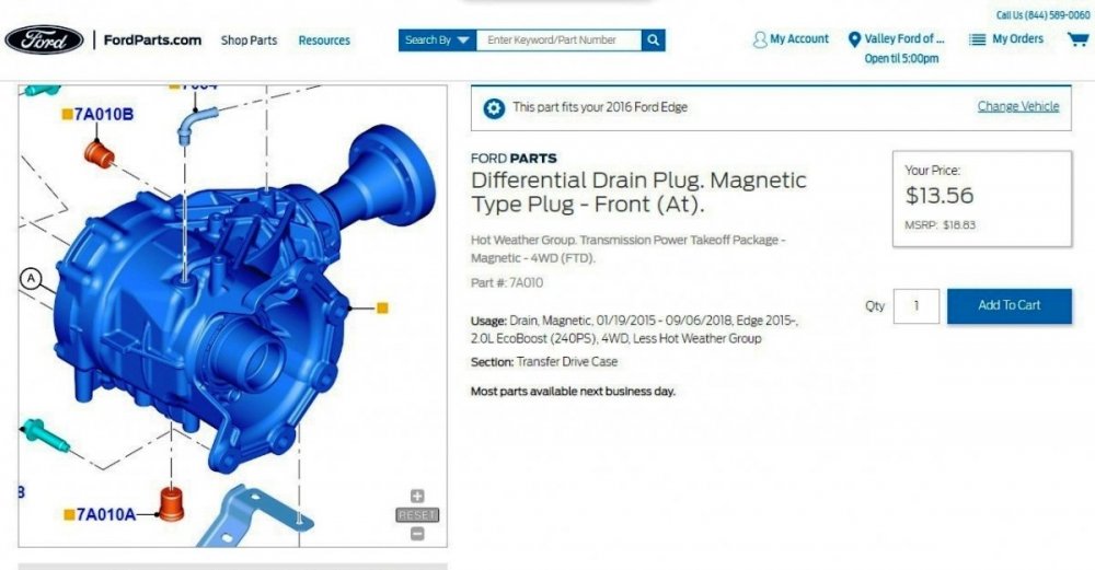
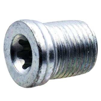
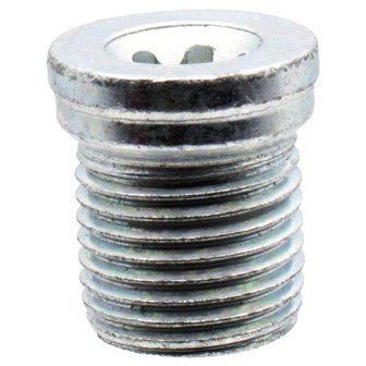
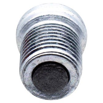
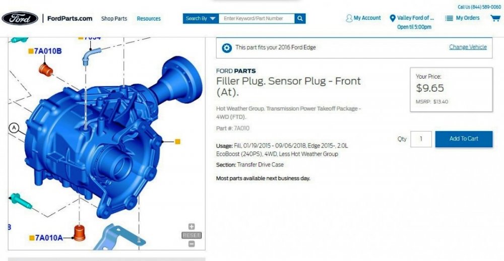
From Ford's online parts site... Magnetic Drain Plug part number: CV6Z-7A010-A FordParts.com page link for Magnetic Drain Plug Filler Plug part number: CV6Z-7A010-B FordParts.com page link for Filler Plug Web searching the part numbers may reveal lower pricing via other online sellers. Good luck!

-
Removing Side Roof Panels?
Haz replied to TonyP's topic in Glass, Lenses, Lighting, Mirrors, Sunroof (BAMR), Wipers
The Edge Workshop Manual provides a General Procedures description for Fixed Glass, but the Workshop Manual lacks a separate procedure for the removing and installing the windshield. Document download link: Fixed Glass - General Procedures - 2015 Edge Workshop Manual.pdf Online videos here and here show aftermarket firms performing windshield installations on GEN 1 Edges with their Panoramic Roof front & side trim panels in place and unaffected. One minimal risk to the roof trim panels could develop when the technician is standing upon he tdoor opening while cutting, cleaning, or applying glass sealant, and perhaps put his/her weight on the trim panel using hand, forearm, or elbow. Were you able to retrieve the blown-off trim panel, in order to determine if it was retained only by the trim clips, or if it also showed adhesive remnants on the trim panel, or if the panel wasn't recovered -- on the corresponding roof structure? Good luck! -
Perhaps you were not logged into the Forum when you attempted to access the downloads... Good luck!
-
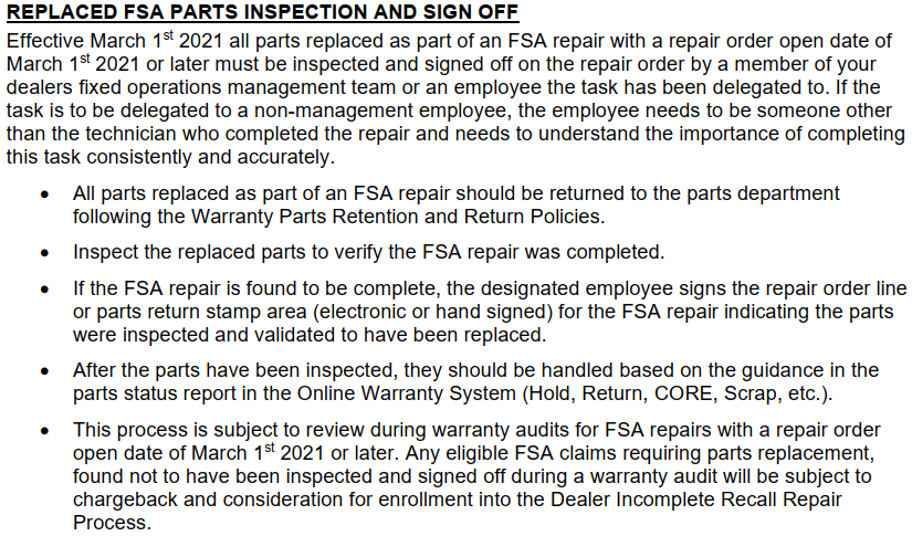
Because you're personally doing the Recall repair work, it would be nice if your dealer found a way to grant you the half-hour of claimable Labor in FordPass Reward points... I'd expect them to submit for administering your Edge's Recall fulfillment, but not for the half-hour Labor you are supplying. I believe you mentioned previously, that they need the parts you remove, in order to technically complete their Inspection sign-off process... Good luck!


-
Document download link...TSB 22-2104 - Seat Pan Looseness, Lateral Movement, Or Clunk-Thump Noise On Turns.pdf The above-linked Technical Service Bulletin 22-2104 applies to 2015-2022 Edge, 2016-2018 MKX, 2019-2022 Nautilus, and numerous other models. New Vehicle Limited Warranty (NVLW)/Service Part Warranty (SPW)/Special Service Part (SSP)/Extended Service Plan (ESP) should cover the surprisingly simple repair procedure. Relating to the fore-aft seat movement problem... I've experienced this when the driver seat on both our 2012 & 2015 MKXs was adjusted entirely rearward upon seat track backstops. I've found that moving the seat slightly forward off the backstops eliminated the fore-aft movement problem. Our MKXs did not exhibit any lateral movement, perhaps due to their being GEN 1 models, while the above-linked TSB applies only to GEN 2 Edge/MKX/Nautilus model years. Good luck!
-
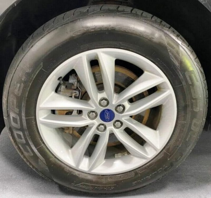
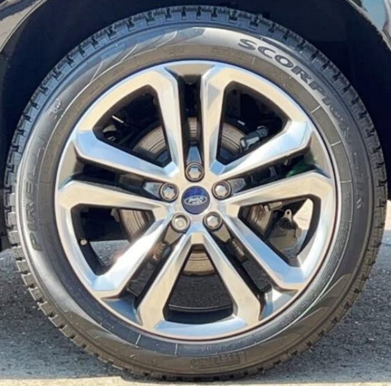
Embarking upon further research, from a prominent vehicle sales website I obtained VINs for a 2015 SEL with 18s and for a 2018 Sport with 20s. Next, I pulled Historic Vehicle Bill of Materials (HVBoM) Reports for each VIN to obtain part numbers for brake rotors and brake calipers installed on each vehicle. In addition to the original part numbers, HVBoM Reports often provide Motorcraft service replacement part references, in this case, for the brake rotors. Both Edges show Motorcraft BRRF364 vented brake rotors for the fronts and Motorcraft BRRF393 solid brake rotors for the rears. Both Edges show front brake caliper part numbers as F2GC2010 (RH) and F2GC2011 (LH), with NC suffix (2015) and NF suffix (2018); and rear brake caliper part numbers DG9C2D250 (RH) and DG9C2D251 (LH), with GD suffix (2015) and GG suffix (2018). For visual reference of caliper-to-rim clearance, the following are images of the Edges from the vehicle sales website.. 2015 Edge SEL AWD with 18" painted aluminum wheel and 245/60R18 tire (front) 2018 Edge Sport AWD with 20" alloy wheel and 245/50R20 tire (rear) Good luck!
-
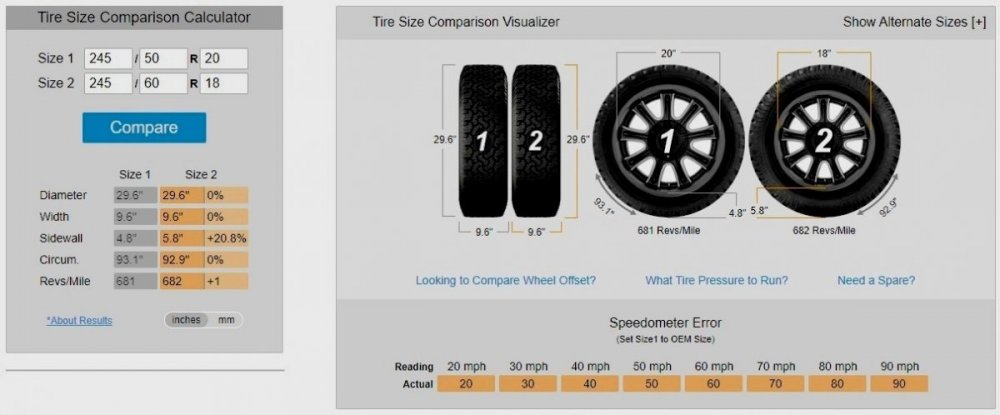
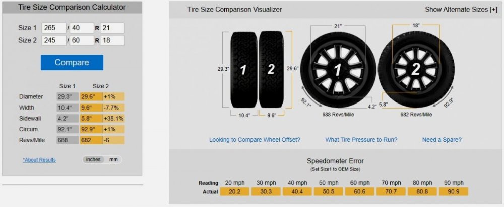
According to Wheel-Size.com, the 2015/2018 bolt circles (5 x 108 mm / 5 x 4.5 in), center bores (63.4 mm), and stud sizes (M14 x 1.5) are identical. The following tire dimension & speedometer error comparisons are from TireSize.com (click on image to enlarge and/or save)... Standard 2018 Edge Sport 20" tire versus 2015 Edge 18" tire Optional 2018 Edge Sport 21" tire versus 2015 Edge 18" tire Good luck!
-
Depending upon the Diagnostic Trouble Codes (DTCs) involved in triggering the Malfunction Indicator Light (MIL), and whether your Edge is exhibiting any white smoke/steam out of the tailpipe which may be related to the low coolant condition, you may want to print this Technical Service Bulletin (TSB) and take it with you to the dealership... Document download link: TSB 20-2234 - 2.0L EcoBoost - Illuminated MIL With Various DTCs, Low Coolant Level, White Smoke From Tailpipe, External Coolant Leak.pdf Good luck!
-
Document download links... Blower Motor - Removal and Installation - 2016 Edge Workshop Manual.pdf Blower Motor Speed Control - Removal and Installation - 2016 Edge Workshop Manual.pdf Blower Motor Removal Remove the push pins and the RH insulation panel. Disconnect the electrical connector. Disconnect the electrical connector, detach the wiring harness retainer and position aside the harness. Remove the retainers and the blower motor. Installation To install, reverse the removal procedure. Good luck!
-
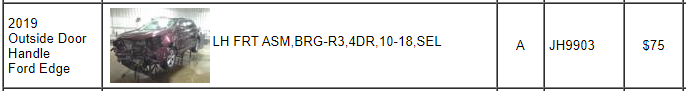
Just in case you would consider a recycled part, I found this 2019 Burgundy Velvet LH door handle using Car-Part.com. Good luck!
-
Welcome to the Forum! Take your vehicle to your local national-brand parts store and ask them to scan it for Diagnostic Trouble Codes (DTCs), which may explain the multiple system fault messages displayed on the left-side dash screen. Take a phone-camera shot of each DTC description shown on their scanner, and then ask them to clear all codes, which they may do free of charge or for a nominal fee. If you have restored the fuse and have not harmed any electronic modules with your wiring misstep, then you may be good-to-go. If any DTCs persist after the code-clearing attempt, report them here, and then we can offer better-informed guidance. Be kind to the parts store workers who are trying to help you. Good luck!
- 1 reply
-
- 1
-

-
- crossed wires
- all lights on
- (and 2 more)
-
Just to ensure you have the full procedure (download link)... Floor Console Removal and Installation - 2013 Edge Workshop Manual.pdf Good luck!
-
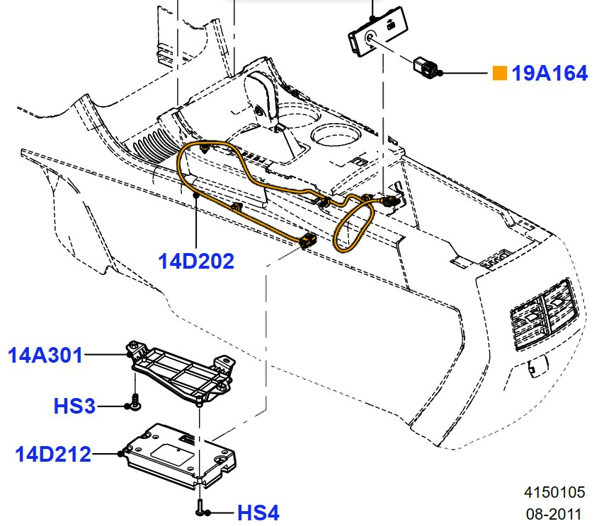
Welcome to the Forum! 2013 Edge SE with Equipment Group 100A, the purely base model, has Premium MyFord Audio System without SYNC, a 4.2-inch non-touchscreen Front Control Display Interface Module (FCDIM), one 2-way speaker in each front door and rear door, AM/FM single CD Audio Front Control Module (ACM) and Audio input jack, Steering wheel controls. . 2013 Edge SE with Equipment Group 101A, has Premium MyFord Audio System with SYNC, a 4.2-inch non-touchscreen Front Control Display Interface Module (FCDIM), one 2-way speaker in each front door and rear door, AM/FM single CD Audio Front Control Module (ACM) and Audio input jack, Satellite radio, Universal Serial Bus (USB) port, Steering wheel controls including the SYNC 'Voice' button . The Ford's online parts site offers this illustration of the APIM's location within the front floor console... . The 2013 Edge workshop Manual provides this illustration with removal & installation procedure and principles of operation description... Edge, MKX Accessory Protocol Interface Module (APIM) - 4.2 inch screen Item Part Number Description 1 W790128 Accessory Protocol Interface Module (APIM) screws (3 required) 2 14D212 APIM 3 W790141 APIM bracket screws (3 required) 4 14A301 APIM bracket 5 — APIM electrical connector (part of 14B709) 6 14D202 Universal Serial Bus (USB) cable . Vehicles with 4.2 inch screen Remove the front floor console. Remove the floor console rear trim panel. Remove the 5 screws and the remove floor console HVAC duct. Remove the 3 screws and remove the APIM from the mounting bracket. Disconnect the electrical connectors. To install, tighten to 0.6 Nm (5 lb-in). All vehicles To install, reverse the removal procedure. If a new APIM is being installed, program the APIM to the correct software level. Principles of Operation - Accessory Protocol Interface Module (APIM) The APIM contains an on-board Bluetooth chipset, which enables certain wireless devices to interact with the system. The APIM consists of two internal modules: the Consumer Interface Processor (CIP) and the Vehicle Interface Processor (VIP) . The modules are not replaceable individually, but can be flashed independently, if required. The CIP interfaces with all of the inputs to the APIM . It contains an analog-to-digital-to-analog converter, as well as the Bluetooth chipset. Any application upgrades that are available to the consumer are loaded directly to the CIP through the Universal Serial Bus (USB) port. In addition to audio information, metadata (information as artist, album title, song title, and genre) may also be sent to the APIM from a device plugged into the USB port. The APIM uses the metadata to create indexes that can be used to sort for particular music, based on customer preference. Not all USB devices can send metadata to the APIM . When a new media device is connected to the SYNC® system, the APIM automatically indexes the information. This may take several minutes (depending on the amount of data on the device), and is considered normal operation. When a device that was previously connected to the SYNC® system is reconnected, the APIM updates the index (rather than creating a new one), which reduces the amount of time needed to index the device. The VIP provides an interface between the CIP and the vehicle. Its main functions are controlling the APIM power management and translating both inbound and outbound signals over the Controller Area Network (CAN) . In addition, the VIP queries the modules on the network to retrieve any DTCs when a vehicle health report is requested. The APIM receives stereo and mono inputs. For Vehicles With The Front Control/Display Interface Module (FCDIM) : The mono output from the APIM utilizes separate circuits from the stereo output. Stereo inputs include audio from the USB port, audio input jack, connected Bluetooth media device, and outside device during a phone call. The mono input includes signals from the SYNC® microphone. The APIM sends stereo and mono audio signals to the ACM as fluctuating AC voltage. Stereo outputs include audio from the USB port, audio input jack, and connected Bluetooth-enabled media device. Mono outputs include audio from the TTS feature, incoming call ringtone, ringback tone, outside device during a phone call, voice or tone prompts initiated from the voice steering wheel switch and FCIM , route guidance voice or tone prompts (if equipped with SYNC® Services), and SYNC® system instructions. With you having already removed the floor console's side trim panels, this exploded components diagram may be familiar to you... Item Part Number Description 1 78061A17 LH upper finish moulding 2 W710338 RH upper finish moulding clip (5 required) 3 W710338 LH upper finish moulding clip (5 required) 4 78061A16 RH upper finish moulding 5 7804608 RH floor console side trim panel 6 W712427 Floor console side trim panel clip (12 required) 7 W712427 Floor console rear trim panel clip (6 required) 8 78045E24 Floor console rear trim panel 9 W712427 Floor console side trim panel clip (12 required) 10 7804609 LH floor console side trim panel SYNC document download link... SYNC Technology Information Guide.pdf Good luck!


-
Following up on the initial post, and while this Special Service Message expresses faulty USB media hub conditions in 2021 and 2022 Edges... Ford has released TSB 22-2404 for 2021 Edge/Nautilus + other 2021 models to address issues consistent with those described in this SSM 51076. Good luck!
-
SSM 52882 Unable To Update APIM, TCU Or GWM With FDRS And USB Drive - TSB 22-2404 Module Recovery App No Longer Available on FDRS - *** Issued on September 12, 2024 *** Some 2021 Bronco, Edge, F-150, Nautilus, and Mustang Mach-E vehicles, technicians may experience an inability to update the accessory protocol interface module (APIM), telematics control unit (TCU), and/or gateway module (GWM) using the Ford Diagnosis and Repair System (FDRS) and Universal Serial Bus (USB) drive. If this occurs, the PTS – Over The Air (OTA) Dashboard may also display multiple APIM and/or TCU updates have failed, and/or a no OTA history message. In addition, the customer may have reported experiencing an OTA software update failure message via the vehicle display and/or FordPass/LincolnWay. Technicians are advised to refer to the appropriate Workshop Manual section for diagnosis and repair of the condition. TSB 22-2404 has been decommissioned and the FDRS Module Update Repair Application is no longer available. _______________________________________________________________________________________________________________________________________________________________________________ Document download link ... TSB 22-2404 - Unable To Update The APIM, TCU Or GWM With The FDRS And USB Drive - Module Recovery.pdf Please Note: In the below post, information not relating to Edge/Nautilus has been removed, but all are included in the above-linked TSB 22-2402 document. TSB 22-2404 emphasizes: Only 10% of vehicles may require this procedure. TECHNICAL SERVICE BULLETIN Unable To Update The APIM, TCU Or GWM With The FDRS And USB Drive - Module Recovery 22-2404 31 October 2022 This bulletin supersedes 22-2150. Model: Ford 2021 Bronco 2021 Edge 2021 F-150 2021 Mustang Mach-E Lincoln 2021 Nautilus Summary This article supersedes TSB 22-2150 to update the Service Procedure. Issue: For some 2021 Mustang Mach-E, F-150, Edge, Nautilus and Bronco vehicles technicians may experience the inability to update the accessory protocol interface module (APIM), telematics control unit (TCU) or gateway module (GWM) using the Ford Diagnosis and Repair System (FDRS) and Universal Serial Bus (USB) drive. The PTS – OTA Dashboard on vehicles with this condition may also display multiple APIM and/or TCU updates have failed, and/or a no OTA history message. In addition, on vehicles with this condition, the customer may have reported experiencing a Ford Power-Up software update failure message via the vehicle display and/or FordPass/LincolnWay. This may be due to an internal software error. To correct this condition, follow the Service Procedure to update and/or recover the APIM/TCU. NOTE: Only 10% of vehicles may require this procedure. Action: Follow the Service Procedure to correct the condition on vehicles that meet all of the following criteria: • 2021 Mustang Mach-E/F-150/Edge/Nautilus/Bronco • Inability to update the APIM, TCU or GWM using the FDRS and USB drive Special Tool(s) USB-to-Ethernet adapter: Trendnet TU2-ET100 USB2.0, Trendnet TU3-ETG USB 3.0, Startech USB31000S USB 3.0, UGREEN USB USB 3.0 model no 40321, Amazon Basics USB 3.0 U3-GE-1P. These adapters have been validated through Ford service testing. Mini B 5 Pin Female Adapter: Rotunda Part# CCMUSB-AF-BF5 or equivalent (Vehicles with USB Media Hub) USB 2 Cable - Male to Male: Rotunda Part# CCMUSB2-AM-AM-10 or equivalent (All vehicles) Ethernet cable assembly, obtain locally (All vehicles) NOTE: Ford has received feedback from technicians that the following USB-to-Ethernet adapters do not work and should not be used: TP-Link USB3 - 10/100/1000, Cable Creations 10/100/1000 USB3, UGREEN USB2 - 10/100, Cable Leader USB 2.0, UGREEN FBA_20256. In the near future, a list of good/bad USB-to-Ethernet adapters will be published on PTS > Service Tips. Warranty Status: Eligible under provisions of New Vehicle Limited Warranty (NVLW)/Service Part Warranty (SPW)/Special Service Part (SSP)/Extended Service Plan (ESP) coverage. Limits/policies/prior approvals are not altered by a TSB. NVLW/SPW/SSP/ESP coverage limits are determined by the identified causal part and verified using the OASIS part coverage tool. Labor Times Description Operation No. Time Download And Run The Module Repair Application Following The Service Procedure, Includes Time To Access Connector MT222404 Actual Time Repair/Claim Coding Causal Part: 14G670 Condition Code: 04 Service Procedure CAUTION: Due to Ford cyber security requirements, the module repair procedure outlined in this article is limited to a maximum of 15 attempts with a total of 20 days from the first time the application is run before the application is permanently disabled for each unique VIN. Make sure that all required and compatible tooling listed in this article is available prior to performing this procedure to reduce the chances of encountering this lockout state. If a lockout occurs, module replacement may be necessary. Note that even if the application is run successfully, the 20 day timer (allowing 15 attempts) continue to run in the background. If the module repair application has successfully completed in the past, it is not required to be run again. NOTE: Administrative access on the laptop computer being used is required to perform this procedure. Make sure any antivirus software loaded in the laptop computer is disabled or uninstalled prior to performing this procedure. NOTE: Use only a wireless connection for internet access as this application requires the use of the laptop computer ethernet port during the module recovery procedure. Verify the FDRS is at the latest software level. 1. Connect either the vehicle communications module (VCM) II or VCM III to the data link connector (DLC) and start a vehicle session using the FDRS. Navigate to the toolbox tab on FDRS then select the Multi Module tab. Under the Multi Module tab, download and run the Module Update Repair application. 2. Does the FDRS application provide the following message: This vehicle does not qualify for Module Update Repair. The TSB does not apply to this vehicle concern? (1). Yes - this article does not apply. Continue with following other service publications for APIM, TCU or GWM programming and/or the Workshop Manual (WSM) for normal diagnostics. (2). No - proceed to Step 3. 3. Connect a battery charger to the vehicle's 12v battery. Set the charger to maintain the battery at 12.6-13.6 volts. 5. For Mustang Mach-E, Nautilus, and F-150 vehicles equipped with a SYNC Media hub, access the APIM in-line USB connector. (4). For Nautilus vehicles, remove the floor console lower right hand trim panel and disconnect the APIM in-line USB connector. Refer to Step 1 in Workshop Manual (WSM), Section 501-12 floor console removal. (Figures 9-10) Figure 9 Figure 10 (5). For Edge vehicles, remove the SYNC media hub and disconnect the mini-USB connector on the back of the media hub. Refer to Step 1 in Workshop Manual (WSM), Section 415-00 Media Hub removal. (Figure 11) Figure 11 (6). For Bronco vehicles, remove the SYNC media hub and disconnect the mini-USB connector on the back of the media hub. Refer to Steps 1 through 5 in WSM, Section 415-00 Universal Serial Bus (USB) Hub removal. Step 5 allows access to the mini-USB connector. NOTE: Verify you have the appropriate Special Tools listed in this document. Failure to use the approved Special Tools may result in application failure. The application may only be run a maximum of 15 times within a 20 day timeframe for each VIN. Refer to the error condition table at the end of this article for further reference. 6. The FDRS prompts the installation of either USB or ethernet cable connections based on the failure detected. Allow the FDRS to establish an ethernet connection before continuing with the process. Moving too quickly prevents the FDRS from identifying the network and affects the recovery process. Once the ethernet connection is identified, select continue. Required USB connections: • Mustang Mach-E, Edge, Nautilus, Bronco and F-150 vehicles equipped with a SYNC Media hub: - Connect the Mini B 5-pin female adapter to the vehicle harness. - Connect the USB 2 Cable - male-to-male to the female adapter and the laptop USB port. Figure 12 Item Description 1 FDRS 2 USB 2 Cable (male-to-male) 3 Mini B 5-pin female adapter 4 Vehicle harness Figure 14 - Edge Figure 15 - Nautilus Required ethernet connections: • Mustang Mach-E, Edge, Nautilus, Bronco and F-150 vehicles equipped with a SYNC media hub: - Connect the Mini B 5-pin female adapter to the vehicle harness. - Connect the USB-to-ethernet adapter to the female adapter. - Connect the ethernet cable to the USB-to-ethernet adapter and laptop ethernet port. Figure 22 - Edge Figure 23 - Nautilus NOTE: Make sure to use the appropriate Special Tools listed in this document. Failure to use the approved Special Tools may result in application failure. The application may only be run a maximum of 15 times within a 20 day timeframe for each VIN. Refer to the error condition table at the end of this article for further reference. NOTE: Make sure any antivirus software loaded in the laptop computer is disabled or uninstalled prior to performing this procedure. 7. Continue following the FDRS on-screen prompts until the procedure is complete. The FDRS displays when to disconnect the cables. Restore the vehicle harness connections. 8. Once this procedure is complete, FDRS returns to the toolbox tab. Check the Professional Technician System (PTS) website for applicable SYNC 4 and Reverse Brake Assist System TSB, SSMs, GSB publications to update the APIM, TCU and/or GWM to the latest software level. Error Condition Table Error Message in FDRS Cause Actions Unable to communicate with vehicle through ethernet adapter. Verify that the ethernet adapter being used is compatible per the TSB. • Incompatible or faulted USB-to-Ethernet adapter • Verify the USB-to-Ethernet adapter that is being used is on the Ford recommended list. Re-attempt programming with a different adapter This vehicle does not qualify for Module Update Repair. The TSB does not apply to this vehicle concern. • The APIM and/or TCU modules are not corrupted. The TSB procedure does not apply. • The module repair procedure and TSB does not apply. Refer to Step 2, Substep 1 (Yes response) of this article. Exception trying to obtain diagnostic files from the backend server required to repair this vehicle. This could indicate that this VIN has been locked out. • Due to Ford Cyber Security requirements, the maximum number of attempts has been reached to run this application. Up to 15 attempts or within 20 days, which ever comes first. • Make sure that the module repair application has not previously been completed successfully by reviewing warranty history on PTS or FDRS vehicle history. • Replace the affected module (APIM or TCU) Module Repair has failed due to limited or no connection with the vehicle through the USB cable 1. Incorrect tooling or improper connections to the vehicle. 1. Mini B 5 Pin Female Adapter (Rotunda Part # CCMUSB-AF-BF5 or equivalent) (vehicles with media hub). 2. USB 2 cable – male to male (Rotunda part # CCMUSB2-AM-AM-10 or equivalent). 2. This may also be caused by a fault with the USB port on the computer being utilized or the fastboot driver not being installed. 1. Verify that the proper cable and adapters are being utilized per the TSB 2. Retry the programming using a different USB port on the PC 3. Retry the programming with a different PC 4. Download the fastboot driver following the prompt in the FDRS error message © 2022 Ford Motor Company All rights reserved. NOTE: The information in Technical Service Bulletins is intended for use by trained, professional technicians with the knowledge, tools, and equipment to do the job properly and safely. It informs these technicians of conditions that may occur on some vehicles, or provides information that could assist in proper vehicle service. The procedures should not be performed by "do-it-yourselfers". Do not assume that a condition described affects your car or truck. Contact a Ford or Lincoln dealership to determine whether the Bulletin applies to your vehicle. Warranty Policy and Extended Service Plan documentation determine Warranty and/or Extended Service Plan coverage unless stated otherwise in the TSB article. The information in this Technical Service Bulletin (TSB) was current at the time of printing. Ford Motor Company reserves the right to supersede this information with updates. The most recent information is available through Ford Motor Company's on-line technical resources.
- 1 reply
-
- 3
-
-
No, not necessarily, from the TSB 22-2419 with emphasis added... NOTE: The APIM software update that addresses the symptom listed in this article may have been delivered over-the-air (OTA) via Ford Power-Up software updates to connected vehicles that have automatic updates enabled through the center display screen. Enter the vehicle identification number (VIN) in Professional Technician System (PTS) and check the OTA Dashboard under the Connected Vehicle tab for OTA update history. If an update to the APIM has been successfully completed recently and the customer is reporting the symptoms are no longer present, this article may not apply. Good luck!
-
Document download link... TSB 22-2419 - 2021-2022 Edge & Nautilus - Inoperative Front Camera Below 6 MPH, Sirius Satellite Radio and Various SYNC 4 Concerns.pdf TECHNICAL SERVICE BULLETIN Inoperative Front Camera Below 6 MPH (10 Km/h), Sirius Satellite Radio And Various SYNC 4 Concerns 22-2419 31 October 2022 This bulletin supersedes 22-2062. Model: Ford 2021-2022 Edge Lincoln 2021-2022 Nautilus Summary This article supersedes TSB 22-2062 to update the Issue, Action and Service Procedure. Issue: Some 2021-2022 Edge/Nautilus vehicles may experience one or more of the following symptoms: inoperative front camera if the camera system button is pressed once the vehicle is below the speed threshold of 6 mph (10 km/h) (Edge Only), Android Auto connection concerns, Apple CarPlay connection concerns, center display screen freezing/locking up, windows media audio (WMA) files not playing properly from a universal serial bus (USB) device, intermittent blank center display screen, Bluetooth connectivity concerns, incorrect Owner's Manual language for French, frozen or delayed touch response for center display screen. This may be due to the software in the accessory protocol interface module (APIM). To correct the condition, follow the Service Procedure to reprogram the APIM. NOTE: The APIM software update that addresses the symptom listed in this article may have been delivered over-the-air (OTA) via Ford Power-Up software updates to connected vehicles that have automatic updates enabled through the center display screen. Enter the vehicle identification number (VIN) in Professional Technician System (PTS) and check the OTA Dashboard under the Connected Vehicle tab for OTA update history. If an update to the APIM has been successfully completed recently and the customer is reporting the symptoms are no longer present, this article may not apply. Action: Follow the Service Procedure steps to correct the condition on vehicles that meet all of the following criteria: • 2021-2022 Edge/Nautilus • At least one of the following: - Inoperative front camera if the camera system button is pressed once the vehicle is below the speed threshold of 6 mph (10 km/h) (Edge Only) - Android Auto connection concerns - Apple CarPlay connection concerns - Center display screen freezing/locking up - WMA files not playing properly from a USB device - Intermittent blank center display screen - Bluetooth connectivity concerns - Incorrect Owner’s Manual language for French - Frozen or delayed touch response for center display screen Warranty Status: Eligible under provisions of New Vehicle Limited Warranty (NVLW)/Service Part Warranty (SPW)/Special Service Part (SSP)/Extended Service Plan (ESP) coverage. Limits/policies/prior approvals are not altered by a TSB. NVLW/SPW/SSP/ESP coverage limits are determined by the identified causal part and verified using the OASIS part coverage tool. Labor Times Description Operation No. Time 2021-2022 Edge/Nautilus: Reprogram The Appropriate Modules As Required By The Software Update And Service Procedure (Do Not Use With Any Other Labor Operations) MT222419 Actual Time Repair/Claim Coding Causal Part: 14G670 Condition Code: 04 Service Procedure NOTE: Ask the customer to bring their spare key fob to assist in the Ford Diagnosis and Repair System (FDRS) programming. The time required to complete this procedure will vary depending on several factors including the number of module software updates required, available internet bandwidth, universal serial bus (USB) flash drive variability, and the potential that controller area network (CAN) flashing (software update via the data link connector [DLC] with FDRS) may be required. It is recommended to connect to the internet with an ethernet cable and use a USB 3.0 capable flash drive when performing software updates. NOTE: The following modules may each require more than one software update: gateway module (GWM), telematic control unit (TCU), accessory protocol interface module (APIM) 1. Start an FDRS session and navigate to Toolbox tab > Datalogger > body control module (BCM) and select the BATT_SOC parameter identification (PID). Verify the PID reads 80% or higher. If state of charge (SOC) is less than 80%, charge the battery then navigate back to Toolbox tab > BCM > Reset Battery Monitor Sensor Learned Values application. Perform the battery monitor sensor (BMS) reset. (1). If the battery is unable to achieve an 80% SOC then a new battery may be required. Use the Rotunda GRX-3590 or DCA-8000 testers to verify if replacement is required. If the battery is replaced, fully recharge the new battery. Then disconnect the Rotunda charger and perform a BMS reset using the FDRS scan tool. 2. Reconnect the battery charger and set it to maintain a vehicle voltage of 12.6 – 13.6 volts. A low battery state of charge while performing a software update to any module may result in a repeat Restart Required message in the vehicle center display screen or a message on the FDRS saying Part Number Validation Failed or DID Validation Failed. 3. Close all the doors on the vehicle. If a door must be left open during the service procedure, the door latch should be mechanically latched to simulate a closed door. 4. Are there any updates available for the GWM, TCU and APIM modules? (1). Yes - proceed to Step 5. (2). No - this article does not apply. Refer to Workshop Manual (WSM), Section 415-00. 5. Perform the Module Software Updating Procedures outlined below for the following modules: GWM, TCU and APIM. Perform a network test after each software update using the latest software level of the FDRS scan tool. This will refresh the list of modules that have available software updates based current module software levels. Continue performing software updates to the GWM, TCU and APIM until all available software updates for those modules are complete. If any error conditions are experienced during programming, refer to WSM Section 418-01A > General Procedures > Module Programming for the Error Condition Table. 6. If the in-vehicle center display screen on a 2021 Edge/Nautilus vehicle does not indicate that the USB flash drive has started to download, this may require recovery of the APIM module. Refer to related Technical Service Bulletins (TSB) or Special Service Messages (SSM) for APIM recovery using the FDRS service tool. Module Software Updating Procedure The following instructions apply when performing a software update on any of the following modules: • GWM • TCU • APIM NOTE: A blank 64GB or larger USB flash drive is required, and a USB 3.0 USB flash drive is recommended for fastest software installation. Make sure the USB flash drive being used is formatted as exFAT file system. To confirm the USB flash drive is formatted as exFAT, hold down the Windows icon keyboard key and press the E keyboard key. Right click on the USB flash drive, then select Properties. If File System under the General tab is not exFAT, the drive must be formatted. To format the USB flash drive, right click on the USB flash drive, select Format, select exFAT for the File System, and select Default Allocation Size for the Allocation Unit Size. De-selecting Quick Format is not necessary and results in a more lengthy operation. 1. Using the FDRS, begin module programming by selecting the SW Updates tab. Download and run the application for desired module. Follow all on-screen instructions carefully. 2. When prompted, connect the USB flash drive to the FDRS. NOTE: It may take up to 5 minutes for the vehicle to recognize the USB flash drive. 3. When prompted by the FDRS, safely remove/eject the USB flash drive from the FDRS and connect it to the USB hub to install the software into the module. When the USB software update begins the center display screen displays a message stating Do Not Remove USB. The update starts automatically and may take 10 minutes or longer to complete. If the message stating Do Not Remove USB does not display on the center display screen within 5 minutes of the USB drive being connected to the vehicle’s USB hub select Did The Update Install Successfully > No on the FDRS and follow the on-screen instructions to either attempt USB programming again or perform CAN programming for the module. 4. When the pop-up stating Restart Required appears on the center display screen, turn the ignition OFF, keep the vehicle doors closed, and wait for 10 minutes. Restart the engine (key-on engine running [KOER]). The update is still in process at this time. NOTE: It may take up to 5 minutes before SYNC center display screen displays Update Successful pop up. After 5 minutes if Update Successful pop up is not shown on SYNC center display screen, remove the USB and select yes on the FDRS Was the USB Update Successful prompt (FDRS verifies if the module software update was successfully installed on the module). 5. Once the pop-up stating Update Successful appears on the center display screen, select Close, remove the USB flash drive from the USB hub and connect it to the FDRS, and select Yes on FDRS indicating the update installed successfully. This initiates the remaining automated configuration steps and reports the module assembly, vehicle interface processor (VIP), calibration, customer interface processor (CIP), and application software levels to the Ford online database. Failure to follow this step results in an inaccurate database as well as omitted, improperly installed, or improperly configured applications (features) such as navigation (if equipped). It is normal for the module to reset during this step. © 2022 Ford Motor Company All rights reserved. NOTE: The information in Technical Service Bulletins is intended for use by trained, professional technicians with the knowledge, tools, and equipment to do the job properly and safely. It informs these technicians of conditions that may occur on some vehicles, or provides information that could assist in proper vehicle service. The procedures should not be performed by "do-it-yourselfers". Do not assume that a condition described affects your car or truck. Contact a Ford or Lincoln dealership to determine whether the Bulletin applies to your vehicle. Warranty Policy and Extended Service Plan documentation determine Warranty and/or Extended Service Plan coverage unless stated otherwise in the TSB article. The information in this Technical Service Bulletin (TSB) was current at the time of printing. Ford Motor Company reserves the right to supersede this information with updates. The most recent information is available through Ford Motor Company's on-line technical resources.
-
Auto-Dimming headlamp behaviour
Haz replied to Rchalk's topic in Glass, Lenses, Lighting, Mirrors, Sunroof (BAMR), Wipers
From the 2017 Edge Workshop Manual... Automatic High Beams The automatic high beam system uses an interior rear view mirror mounted camera to monitor surrounding traffic conditions and high beam usage. The camera is hardwired to the IPMA and serviced with the interior rear view mirror assembly. The IPMA communicates light information over the HS-CAN2 to the GWM then the GWM sends the information to the BCM over the HS-CAN1 . The automatic high beam feature is active only when the headlamp switch is in the AUTOLAMPS position. During nighttime driving, the automatic high beam system automatically turns the high beams on if it is dark enough and no other traffic is present. When the system detects an approaching vehicle's headlamps or a preceding vehicle's rear lamps, the system turns off the high beams. When the approaching vehicle's headlamps or the preceding vehicle's rear lamps are no longer detected, the high beams automatically turn back on. Light levels measured by Image Processing Module A (IPMA) determine the Auto High Beams' on-or-off status, without any consideration of vehicle speed. As you look back on your low-speed versus high-speed experiences, might there have been differences in the presence of street lighting or adjacent-to-road lighting which may be inhibiting the IPMA from actuating high beams more quickly? Good luck!
-
Do you have part numbers for the air deflector panels you have identified online? Good luck!
-
Roof Rack / Rails on newer Edge with Vista Sunroof
Haz replied to tamuin's topic in Cargo, Hauling, Roof Racks & Towing
@scguru92's advice and photos are the best I've seen on this subject for GEN 1 owners... Installed Factory/Thule roof rack on a vista BAMR For tamuin, the trim panels adjacent to GEN 2 Vista roof panels are actually sheet metal, as described in this past discussion. Good luck!- 11 replies
-
- 1
-
-
- bamr
- roof racks
- (and 2 more)
-
SSM 51163 2021 Edge - Sirius Radio Inoperative With Audio Control Module (ACM) DTC B1A89:13 - After APIM Software Update Some 2021 Edge vehicles which have received an APIM software update may experience a concern with Sirius radio being inoperative. This will be accompanied by ACM diagnostic trouble code (DTC) B1A89:13 for the satellite antenna. To correct this condition, download and run the APIM Programmable Module Installation (PMI) application using the latest software level of the Ford Diagnosis and Repair System (FDRS). When the PMI asks, Is The Original Module Installed?, select NO. When the PMI completes, perform an ALL CMDTC test and clear all DTCs. For claiming, use causal part 14G670 and applicable labor operations in Section 10 of the Service Labor Time Standards (SLTS) Manual.
-
2019 Titanium Adaptive Cruise Brakes Hard For No Reason
Haz replied to waflyboy's topic in 2019-Current Edge & Nautilius
From the 2019 Edge Workshop Manual, with emphasis added... Camera Alignment Camera alignment is required for the lane keeping alert and lane keeping aid to function correctly. The procedure is initiated using the diagnostic scan tool and requires about 10 minutes of driving above 64 km/h (40 mph) on a flat, straight road with highly visible lane markings to complete. NOTE: The alignment completion is indicated on the diagnostic scan tool. If the alignment is unsuccessful, check the IPMA for proper installation. NOTE: The FRONT CAMERA MALFUNCTION - SERVICE REQUIRED message in the IPC disappears when the system is aligned. The IPMA camera alignment procedure should be performed when any of the following occur: Windshield replacement Change in tire size Suspension repair or alignment Front air bag deployment Component Description IPMA The IPMA is located on the windshield, below the interior rear view mirror. The IPMA communicates on the HS-CAN2 and on vehicles equipped with the adaptive cruise control and collision warning system, the IPMA shares information with the CCM on a dedicated CAN circuits to assist the driver in avoiding collision. The IPMA contains a forward-looking camera that is used to detect the position of the vehicle within the lane. The IPMA requires PMI and camera alignment when replaced. Component Location - Lane Keeping System Item Description 1 IPMA 2 Lane Keeping System (LKS) switch Good luck!