Haz
-
Posts
1,460 -
Joined
-
Last visited
-
Days Won
392
Content Type
Profiles
Forums
Gallery
Everything posted by Haz
-
2010 Edge Replaced Radio/Stereo w/Same
Haz replied to RedMeatMike's topic in Audio, Backup, Navigation & SYNC
Your Edge's VIN shows these As-Built values for its ACM... ACM 727-01-01 0C00 907A 68AE ACM 727-01-02 0031 ACM 727-02-01 5B8C Would't hurt to look at the installed 2008 ACM and see if the values match, or, to modify them to these values to determine if it corrects the steering wheel radio controls malfunction. Good luck! -
Headlight replacement
Haz replied to edgemaster's topic in Glass, Lenses, Lighting, Mirrors, Sunroof (BAMR), Wipers
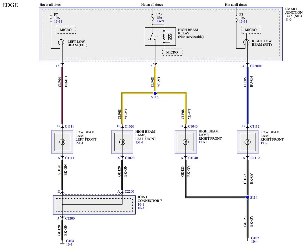
PDF download links for headlamp wiring diagram and electrical connector detail documents from 2009 Edge Workshop Manual... Headlamp Wiring Diagram - 2009 Edge Workshop Manual.pdf LOW BEAM LAMP, LEFT FRONT Connector C1111 Details - 2009 Edge Workshop Manual.pdf HIGH BEAM LAMP, LEFT FRONT Connector C1020 Details - 2009 Edge Workshop Manual.pdf LOW BEAM LAMP, RIGHT FRONT Connector C1112 Details - 2009 Edge Workshop Manual.pdf HIGH BEAM LAMP, RIGHT FRONT Connector C1040 Details - 2009 Edge Workshop Manual.pdf Good luck!
-
2010 Edge Replaced Radio/Stereo w/Same
Haz replied to RedMeatMike's topic in Audio, Backup, Navigation & SYNC
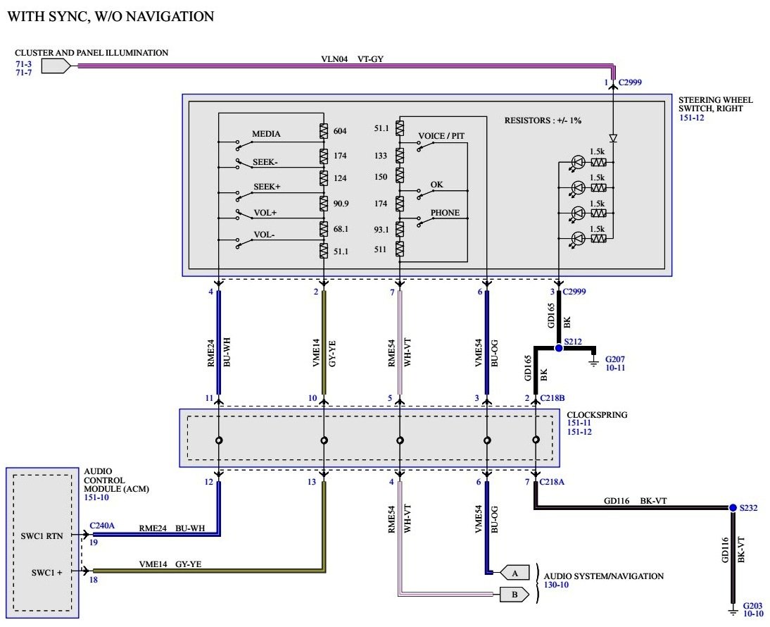
While you're waiting for your USB-wired OBDII dataport adapter, I decided to survey six 2010 Edge SE vehicles' Audio Control Module (ACM) As-Built programming values to determine if Steering Wheel Radio Controls appear to be additionally programmed like the optional installation(s) of SYNC Gen 1 and/or Sirius satellite radio reception. Within VIN-specific Historical Vehicle Bill of Materials (HVBoM) reports, I found two different installed part numbers for AM/FM single CD/MP3 Satellite Capable ACMs: Job 1 vehicles - Installed Part # 9T4T18C869AB with Service/Replacement Part #9T4Z18C869A; Job 2 (change occurred sometime between January 2010 & April 2010) vehicles - Installed Part # AT4T18C869AB with Service/Replacement Part #AT4Z18C869AA; As expected, recognizable programming differences exist in ACMs, depending upon if SYNC Gen 1, or Sirius satellite radio reception, or both of these options were factory-installed. And while 'Job 1' and 'Job 2' ACM part numbers are different, the programming values used in them for these options are identical. Relating to Steering Wheel Radio Controls, surprisingly, I found no ACM programming differences between vehicles equipped without the steering wheel controls (Rapid Spec 100A) versus those equipped with the steering wheel controls (Rapid Spec 101A). This causes me concern, since everything requiring programming in the newly installed ACM is working properly -- except for the steering wheel radio controls, which should be plug-and-play without any added programming. Below are the wiring diagram and electrical connector details for the Steering Wheel Radio Control-to-ACM circuits, just in case you or the ACM Installer Shop need to do circuit diagnostics. It is possible that a pin in the ACM connector has been pushed out or damaged, causing the redundant controls to be inoperative. Or the controls or the ACM may be faulty... Document download links> Steering Wheel Right Side Controls Wiring Diagram - w-SYNC wo-NAV - 2010 Edge Workshop Manual.pdf Audio Control Module (ACM) Connector C240A Details - 2010 Edge Workshop Manual.pdf Audio Control Module (ACM) - Removal and Installation - 2010 Edge Workshop Manual.pdf Clockspring Connector C218A Details - 2010 Edge Workshop Manual.pdf Clockspring Connector C218A Location Illustration - 2010 Edge Workshop Manual.pdf Steering Wheel Controls - Removal and Installation - 2010 Edge Workshop Manual.pdf Information and Entertainment System - Description and Operation - 2010 Edge Workshop Manual.pdf Module Configuration - Diagnosis and Testing - 2010 Edge Workshop Manual.pdf Pinpoint Test F - Steering Wheel Controls Inoperative or Not operating Correctly - 2010 Edge Workshop Manual.pdf If any other Connector information is needed, just let me know and I will provide it. Good luck!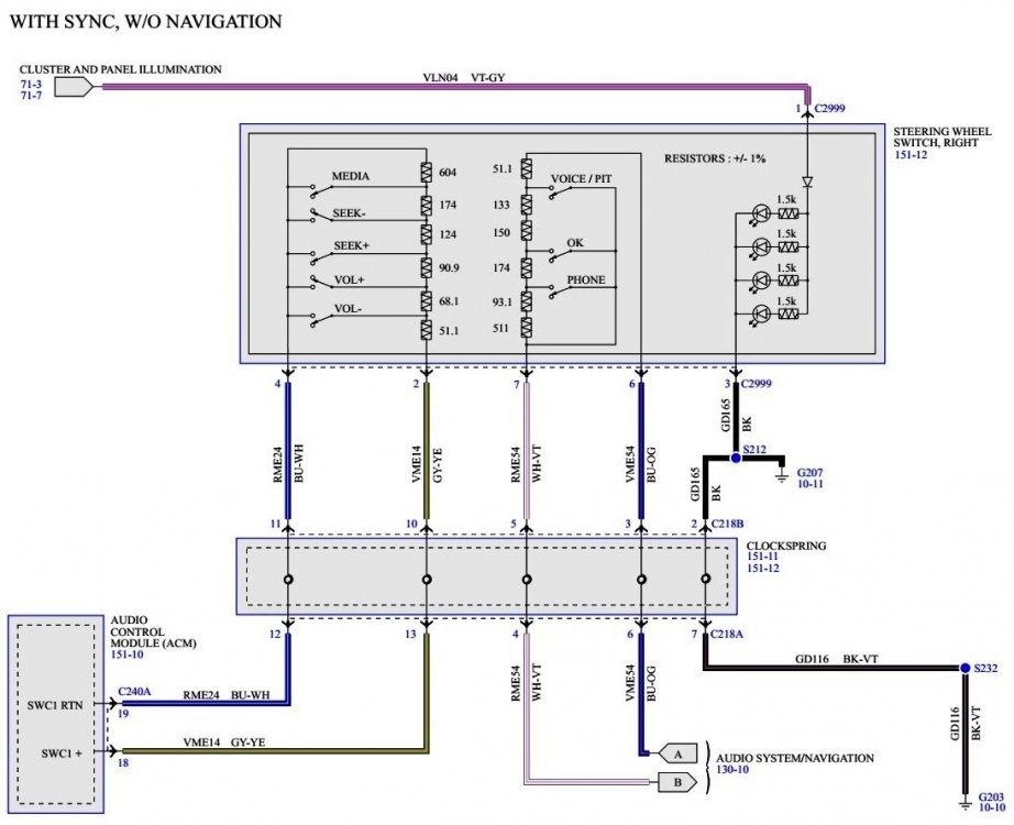
ConnectorC240ADetailswRedHighlights-2010EdgeWorkshopManual.thumb.jpg.60c2acc0b578b0ae2ab534683255762a.jpg)
-
Edge Workshop Manual partial diagnostic Pinpoint Test relating to Rain Sensor/Windshield Wiper effectiveness... F5 CHECK THE WINDSHIELD FOR DAMAGE Ignition OFF. Inspect the windshield glass for any cracks, pits or other visible damage around the area of the rain sensor. Is any windshield damage present near the area of the rain sensor? Yes INSTALL a new windshield. REFER to: Windshield Glass (501-11 Glass, Frames and Mechanisms, Removal and Installation). No GO to F6 F6 CHECK THE WINDSHIELD GLASS FOR STREAKING Ignition ON. Turn the wiper/washer switch to the low speed wiper setting and while applying water to the windshield surface. Observe the wipe quality, especially around the area of the rain sensor. Is any streaking present on the windshield around the area of the rain sensor? Yes GO to F7 No GO to F9 F7 CHECK THE WINDSHIELD WIPER BLADES FOR STREAKING Ignition OFF. Clean the windshield glass with glass cleaner. Clean the wiper blades with isopropyl alcohol swabs. Wipe the entire length of the wiper blades. Ignition ON. Place the wiper/washer switch to the low speed wiper setting and while applying water to the windshield surface. Observe the wipe quality, especially around the area of the rain sensor. Was there noticeable improvement in the wipe quality after cleaning the glass and the wiper blades? Yes GO to F8 No INSTALL new wiper blades. GO to F8 F8 RECHECK THE RAIN SENSITIVE WIPERS OPERATION Place the wiper/washer switch to the auto/intermittent 5 setting (most sensitive to moisture) while applying water on the windshield above the rain sensor. Do the wipers operate when water is applied to the windshield surface? Yes The system is operating correctly at this time. The concern may have been caused by poor wipe quality on the windshield around the rain sensor. No GO to F9 F9 CHECK FOR THE PRESENCE OF THE LENS GEL Ignition OFF. Lightly press the rain sensor against the windshield and release the rain sensor clips. Does the rain sensor remain adhered to the windshield? Yes ATTACH the retaining clips. GO to F10 No The sensor gel-type lens is missing or damaged. INSTALL a new rain sensor. REFER to: Rain Sensor (501-16 Wipers and Washers, Removal and Installation). F10 INSPECT THE RAIN SENSOR MOUNTING AREA NOTE: The rain sensor gel-type lens can be damaged or contaminated during rain sensor removal, rain sensor bracket separation or incorrect installation. From the outside of the vehicle, inspect the area of the windshield glass where the rain sensor is mounted. The rain sensor contact area should appear black, with no bubbles, air pockets or contaminants between the windshield glass and the rain sensor. Does the rain sensor contact area appear black, with no bubbles, air pockets or contaminants between the windshield glass and the rain sensor? Yes GO to F11 No REMOVE and INSTALL the rain sensor correctly. REFER to: Rain Sensor (501-16 Wipers and Washers, Removal and Installation). Document download link> Rain Sensor - Removal and Installation - 2020 Edge Workshop Manual.pdf Interior Rear View Mirror - Removal and Installation - 2020 Edge Workshop Manual.pdf Good luck!
-
Additional reference for Starter Relay location in underhood Battery Junction Box (BJB)... Document download link> Battery Junction Box (BJB) Diagram - 2013 Edge Workshop Manual.pdf Good luck!
Diagram-2013EdgeWorkshopManual.thumb.jpg.3b57c3b60940db7b149fa02dea6b5fcf.jpg)
-
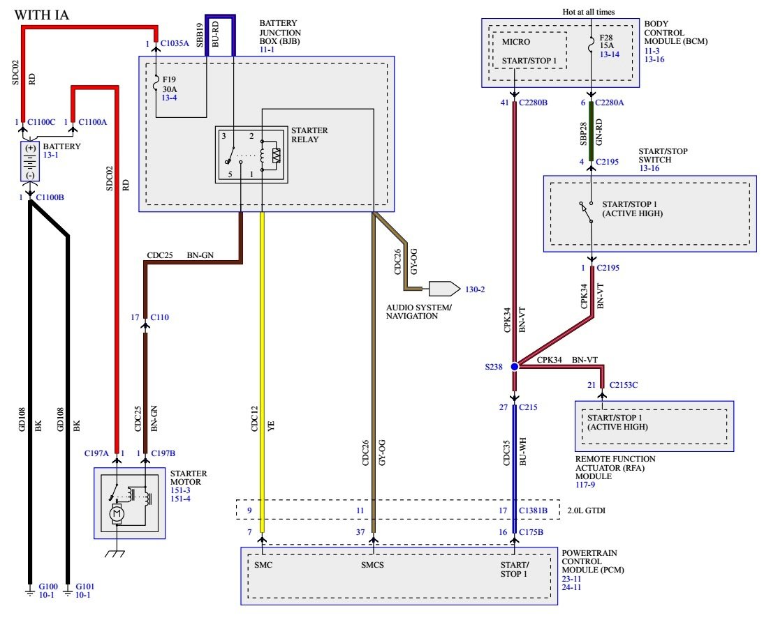
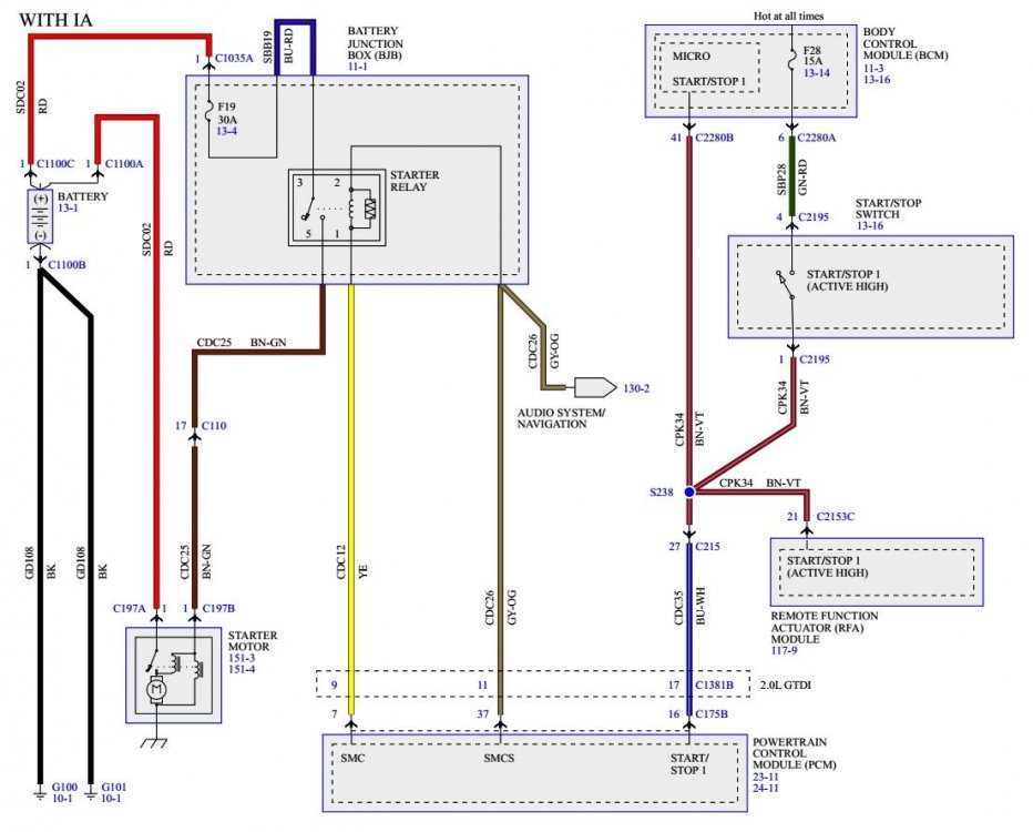
Here is the Intelligent Access (IA) Starting System wiring diagram and a brief operational description from the 2013 Edge Workshop Manual... Principles of Operation — With Intelligent Access (IA) NOTE: This vehicle is equipped with Passive Anti-Theft System (PATS) that disables the engine if an unprogrammed PATS key is used or an invalid PCM ID is received. PATS is controlled by the Remote Function Actuator (RFA) module, BCM and PCM . If the PATS disables the engine from starting, the IPC displays "STARTING SYSTEM FAULT" in the message center. Refer to Section 419-01B to diagnose a PATS concern. The RFA module and the BCM controls the ignition modes and in conjunction with the PCM controls the IA starting system. Under normal operation during a start event, the following inputs are received: Start/stop switch pressed Brake pedal applied Transmission in PARK or NEUTRAL signal from the Transmission Range (TR) sensor Run/start relay voltage. PATS enabled status When the PCM receives the correct inputs, voltage and ground is supplied to the starter relay coil. The starter relay coil is energized causing the relay contacts to close providing voltage to the starter solenoid, allowing the starter motor to crank the engine. The PCM disengages the starter once an engine rpm threshold is reached, a set crank time is exceeded or the start/stop switch is pressed indicating an engine shutdown. The following are PDF download links to relevant Workshop Manual sections... Starting System with Intelligent Access - Wiring Diagram - 2013 Edge Workshop Manual.pdf Starting System - Diagnosis and Testing - 2013 Edge Workshop Manual.pdf Starter Motor - Removal and Installation - 2.0L EcoBoost - 2013 Edge Workshop Manual.pdf Please be aware that the Diagnosis and Testing document is especially thorough and its full application requires capability for scanning the vehicle's electronic modules for Diagnostic Trouble Codes (DTCs) and other state-of-operation indicators, as well as multi-meter evaluation of wiring circuits and connectors. If your corrective efforts take you to this depth of investigation and you require fuller detail on wiring connectors, just let me know and I will provide it. Hopefully, your review of this information will lead to a successful repair. Good luck!
-
As an FYI to jt9813, and with much appreciation to dabangsta for his reminder... Document download link> TSB 20-2234 - 2019-2020 Edge-Nautilus 2.0L Ecoboost EGR Cooler - Low Coolant, White Smoke, Coolant Leak.pdf Good luck!
-
Just to satisfy my own curiosity, I'll try to look at Valencia Engine Plant versus Cleveland Engine Plant sourcing in the affected 2019 Fusion/MKZ/MKC/Escape. Good luck!
-
TSB 22-2229 relating to 2.0L EcoBoost coolant in cylinders applies to 2015-2018 Edges, but it does not extend to model year 2019 Edge production, which began in September 2018 (EDIT 2019). TSB 22-2229 does apply to 2.0L EcoBoost engines in: 2019 Fusion/MKZ built on or before 04/08/2019; 2019 MKC built on or before 04/18/2019; 2019; 2019 Escape built on or before 05/16/2019; So, the 2.0L EcoBoost change was implemented in the April-May 2019 time frame. ( EDIT -- before model year 2019 Edge production began). Good luck! EDIT due to incorrect date.
-
Requesting Wiring Diagram for 6 Way Edge Seats (2009)
Haz replied to horn's topic in Interior, A.C., Heat, Interior Trim
One more document, then... Heated Seats Wiring Diagram - 2009 Edge Workshop Manual.pdf Good luck! -
Requesting Wiring Diagram for 6 Way Edge Seats (2009)
Haz replied to horn's topic in Interior, A.C., Heat, Interior Trim
The following are download links to the requested information in PDF document format... Power 6-Way Driver Seat Wiring Diagram - 2009 Edge Workshop Manual.pdf Power Driver Seat Switch Connector C352 Location Illustration - 2009 Edge Workshop Manual.pdf Power Driver Seat Switch Connector C352 Details - 2009 Edge Workshop Manual.pdf Power Driver Seat Horizontal Motor Connector C362 Details - 2009 Edge Workshop Manual.pdf Power Driver Seat Rear Height Motor Connector C363 Details - 2009 Edge Workshop Manual.pdf Power Driver Seat Front Height Motor Connector C382 Details - 2009 Edge Workshop Manual.pdf Power 6-Way Passenger Seat Wiring Diagram - 2009 Edge Workshop Manual.pdf Power Passenger Seat Switch Connector C355 Location Illustration - 2009 Edge Workshop Manual.pdf Power Passenger Seat Switch Connector C355 Details - 2009 Edge Workshop Manual.pdf Power Passenger Seat Horizontal Motor Connector C332 Details - 2009 Edge Workshop Manual.pdf Power Passenger Seat Front Height Motor Connector C3074 Details - 2009 Edge Workshop Manual.pdf Power Passenger Seat Rear Height Motor Connector C3075 Details - 2009 Edge Workshop Manual.pdf Just curious...What type of vehicle are the seats being transplanted into? Good luck! -
2010 Edge Replaced Radio/Stereo w/Same
Haz replied to RedMeatMike's topic in Audio, Backup, Navigation & SYNC
RedMeatMike: Welcome to the Forum! CARR142 is correct that the As-Built configuration data of the radio/Audio Front Control Module (ACM) that was removed from your Edge must be programmed into the replacement ACM. If the original ACM's configuration was not saved before the replacement ACM was installed, the Edge's original As-Built data file can be easily obtained and Forscan can be used to program the replacement ACM's 727-xxx-xxx module address configuration. Have you gone back to the shop that installed the replacement ACM for you, to report the loss of steering wheel controls after they completed the job? Running the ACM Self-Diagnostic procedure may provide useful information toward resolving the steering wheel controls issue, so follow the directions in the below-linked PDF document... Download link> Audio Control Module (ACM) Self-Diagnostic Mode - 2010 Edge Workshop Manual.pdf Please report back on the results -- and also -- please include which type of radio/ACM and steering wheel controls your Edge is equipped with from among the following descriptions from the 2010 Edge Workshop Manual... The vehicle is equipped with one of the following ACMs : AM/FM single CD Standard for SE trim AM/FM 6-CD changer Available with base, premium Edge audio systems Navigation AM/FM single CD/DVD Built-in satellite radio receiver Voice-activation Touchscreen display The following audio systems are available: Base — Edge AM/FM single CD or AM/FM 6-CD changer ACM One speaker in each door Premium I — Edge AM/FM 6-CD changer or navigation ACM External audio amplifier (with navigation only) One 2-way speaker in each door, subwoofer in the RH rear quarter Premium II — Edge AM/FM 6-CD changer or navigation ACM External audio amplifier (with navigation only) One mid-woofer in each front door, one 2-way speaker in each rear door, 2 A-pillar speakers, subwoofer in the RH rear quarter All audio systems include the following features: Speed sensitive volume Accessory delay Steering wheel controls MP3 capability Satellite-ready Audio input jack The following options are available: Satellite radio SYNC system Optional on Edge There are 4 different steering wheel controls configurations: Non-navigation, without the SYNC system VOL-, VOL+, SEEK-, SEEK+, MEDIA Non-navigation, with the SYNC system VOL-, VOL+, SEEK-, SEEK+, VOICE, MEDIA, PHONE, OK Navigation, without the SYNC system VOL-, VOL+, SEEK-, SEEK+, VOICE, MEDIA Navigation, with the SYNC system VOL-, VOL+, SEEK-, SEEK+, VOICE, MEDIA, PHONE The VOL-, VOL+, SEEK-, SEEK+, and MEDIA buttons are always wired to the Audio Control Module (ACM). Voltage is sent from the ACM to the steering wheel controls, and the ACM grounds the reference voltage. For vehicles equipped with navigation, but not the SYNC system, the VOICE button is wired to the ACM. All of the steering wheel controls share the same signal return circuit. As a result, a failure in the return circuit causes all steering wheel controls to be inoperative. For vehicles equipped with the SYNC system, the VOICE (an icon of someone speaking), PHONE (an icon of a phone with an up and down arrow), and OK buttons are wired directly to the Accessory Protocol Interface Module (APIM) unless the vehicle is equipped with navigation, in which case there is no OK button, and the VOICE and PHONE buttons are wired to the ACM. Voltage is sent from the APIM (or ACM if equipped with navigation) to the steering wheel controls, and the APIM (or ACM if equipped with navigation) grounds the reference voltage. When a switch is pressed, the voltage is routed through a specific resistor value for each function. The ACM (or APIM) then uses the reference voltage to determine which control input function has been selected. Good luck! -
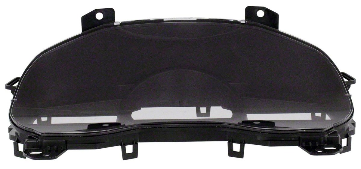
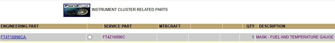
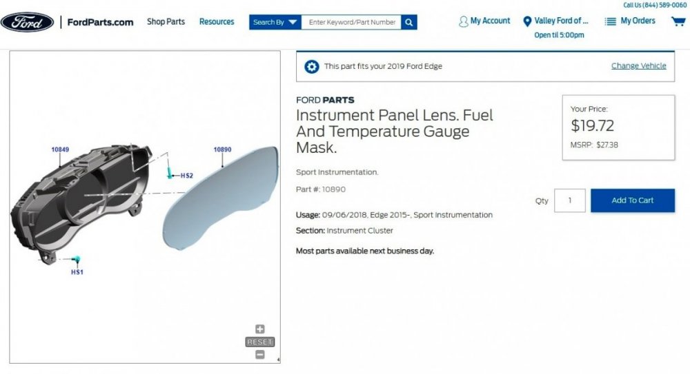
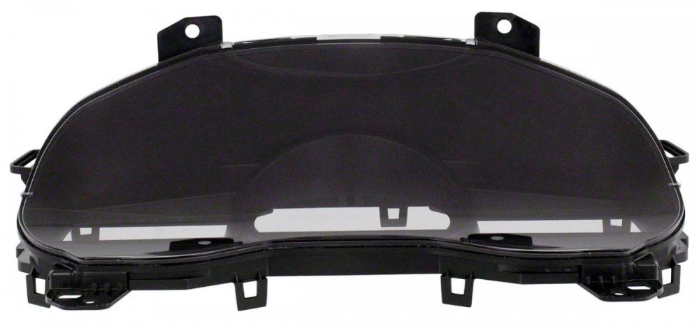
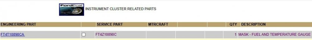
Surprisingly inexpensive, from Ford's online parts site... Low Series Analog Cluster page link Sport Instrumentation Cluster page link Document download link> Instrument Panel Cluster - Removal and Installation - 2019 Edge Workshop Manual.pdf VIN-specific part numbers for Engineering/originally installed and Service/replacement... Good luck!

-
I once removed a faulty Rear Gate Trunk Module and replaced it with a 1960's-era transistor radio, but I had to remove it, because every time the Emergency Broadcast System was tested, the power liftgate would open. Good luck!
-
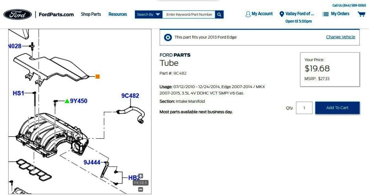
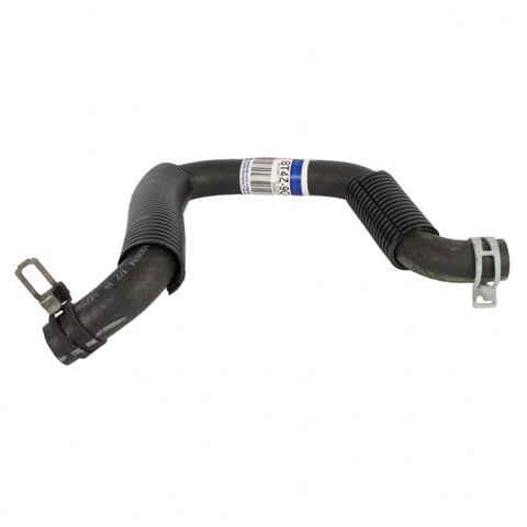
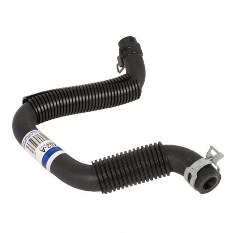
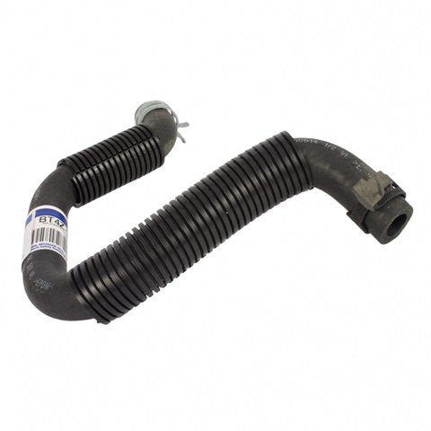
Molded hose is Ford part number: BT4Z-9C482-A Link to Ford's online parts site showing 9C482 Performing a web search of BT4Z-9C482-A may yield improved pricing via online sellers. Good luck!

-
dabangsta: While the 2019 Edge 2.0L EcoBoost you're considering is not listed as affected in the TSB origins of this discussion thread, 2.0L EcoBoost water intrusion issues for 2019-2020 Edge and 2019-2020 Nautilus are addressed by TSB 20-2234, as mentioned in my prior exchange with cherylwilson91, whose extended warranty coverage is saving her from paying for a significant engine repair. As you may already be aware, water intrusion issues on your 2017 Escape's 1.5L EcoBoost were addressed by TSB 22-2322, though as a result of its total-loss collision disposition, title branding may remove any warranty coverage potential if the vehicle is repaired and resold. Document download link: TSB 22-2322 - 1.5L EcoBoost - Low Coolant, White Exhaust Smoke And-Or Illuminated MIL - Built On Or Before 10-Jun-2019 - 08-12 2022.pdf Good luck!
-
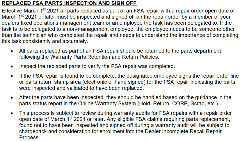
Some 2015-2020 Edge, 2016-2018 MKX, 2019-2020 Nautilus, 2018-2021 Expedition/Navigator, and 2020-2021 Escape/Corsair/Explorer/Aviator vehicles may exhibit an inoperative power liftgate. This may be due to the rear gate trunk module (RGTM) software. To correct the condition, reprogram the RGTM using the latest software level of the appropriate Ford diagnostic scan tool. For claiming, use causal part 14B291 and applicable labor operations in Section 10 of the Service Labor Time Standards (SLTS) Manual. This Special Service Message was released on December 12, 2022.
-
Removing Side Roof Panels?
Haz replied to TonyP's topic in Glass, Lenses, Lighting, Mirrors, Sunroof (BAMR), Wipers
Not sure if your insurance company funded the windshield replacement, but at this point, the front trim and the rear driver's side trim panels are vulnerable to the same loss your Edge has already suffered. Based upon costs quoted above from my earlier post, I'd suggest contacting your insurance company to see what they will cover and what your deductible, if any, will be. If your insurance company paid for the recent windshield replacement, they may have a customer satisfaction feature that may cover the side panel replacement, and then the insurance company would pursue cost recovery from Safelite, without you needing to be concerned about it. Based on your description and your photo, the missing trim panel was -- and all the still-present (for now) trim panels are -- retained only by the original plastic clips, with no urethane adhesive used at the factory. The previously posted 2016 Edge Workshop Manual sections covering roof trim panels describe removal and re-use is possible for trim panels not originally installed with urethane adhesive. For you, that's favorable, since it means those trim panels now remaining in place can be removed and reinstalled using new clips and urethane adhesive to ensure they are not eventually blown off like the now-missing panel. It's worth noting that the Workshop Manual section on Roof Trim Panel Removal and Installation was revised in late January 2017, presumably to include factory installation using urethane adhesive, whenever that revised factory procedure was implemented. When speaking with your Insurance company, it may be worth asking if they would pay for the remaining panels to be reinstalled using urethane adhesive, in order to avoid any future claims for subsequent trim panel loss. Even if they won't cover it, perhaps your dealer or other repair facility will discount their pricing based upon the totality of the job. For the sake of readability, I will include an edited Side Trim Panel procedure from the 2015 Edge Workshop Manual immediately below, and I'll also attach a PDF download links at the end of this post... Roof Opening Panel Side Trim Special Tool(s) / General Equipment Knife Materials Name Specification Sika® SikaTack® MACH 60 / Sika® SikaTack® MACH 30 / Dow® BETASEAL™ Express - Sika Tack ASAP Urethane Adhesive - Dow Urethane One Step Glass Primer Betaprime™ 5500/5500A/5500SA - Sika Urethane Metal and Glass Primer Sika 206 G+P - Bare Metal Etch Primer BETAPRIME 5201 - Removal Front Side Trim Installed Without Urethane NOTE: LH side shown, RH side similar. NOTE: Front side trim that was not assembled with urethane adhesive can be reinstalled. Always reinstall the trim using urethane. NOTE: The rear side trim panel must be removed for access to remove the front side trim panel. Remove the rear side trim. Refer to Rear Side Trim within this procedure. NOTE: The front side trim panel may have been serviced previously and may now have urethane included with no obvious signs. After beginning this step, if the trim seems to have had urethane previously applied, proceed to Front Side Trim Panel Installed With Urethane. NOTE: LH side shown, RH side similar. NOTE: The front of the side trim is tucked under the front trim. After releasing all clips, the side trim can be removed by rotating the rear of the side trim up and removing toward the rear. Remove the front side trim. Detach the retaining clips. Lift the rear of the front side trim enough to clear the front retaining clip for removal. Remove the front side trim toward the rear of the vehicle. Installation Front Side Trim NOTE: All views are LH side shown, RH side similar. If reinstalling the original trim. Remove the round retaining clips from the front side trim. Remove the square retaining clips from the front side trim. NOTE: A new component has all retaining clips installed. If reinstalling the original trim. Attach new round retaining clips to the front side trim. NOTE: The arrow on the square retaining clips must match the embossed arrow on the trim piece at all locations or damage may result. Attach new square retaining clips to the front side trim. NOTE: Avoid scratching the surface metal. Repair all minor scratches or exposed metal following manufacturer's instructions. Use the same brand metal primer and urethane adhesive. Maximum 2 mm (0.08 in) bead thickness. Do not apply bare metal primer to areas with remaining urethane adhesive. New trim must be installed within 2 hours of cutting the urethane adhesive. Cut or scraped urethane becomes oxidized and inactive beyond 2 hours reducing the effectiveness of the repair bond. If the front side trim was previously installed with urethane, trim the urethane adhesive from the frame leaving a 1-2 mm (0.04-0.08 in) base of original urethane adhesive. If any paint layer is damaged extending to bare metal, apply bare metal primer to those areas only. Use the General Equipment: Knife Material: Bare Metal Etch Primer / BETAPRIME 5201 NOTE: Be sure to use the same brand and cure-rate products for the urethane adhesive and glass primer. Do not mix different brands of urethane adhesive and primer. For additional information, refer to the Material Chart in this procedure. Wipe the areas shown with isopropyl alcohol wipes. Apply the specified primer to the trim panel. Material: Sika Urethane Metal and Glass Primer / Sika 206 G+P Material: Dow Urethane One Step Glass Primer / Betaprime™ 5500/5500A/5500SA Allow 30 minutes for the primer to cure. If no urethane adhesive was present during removal, use isopropyl alcohol wipes to clean the area where the urethane will be applied. Apply a 15 mm (0.6 in) high and 25 mm (0.98 in) wide circular spot of the specified urethane adhesive as shown. Material: Sika Tack ASAP Urethane Adhesive Material: Sika® SikaTack® MACH 60 / Sika® SikaTack® MACH 30 / Dow® BETASEAL™ Express Install the front trim pressing firmly along all spacer block and urethane areas and making sure all the clips are fully seated. If necessary use tape and cardboard to hold the trim at the desired height. Allow the urethane to cure for 24 hours. Install the Rear Side Trim. Refer to Rear Side Trim within this procedure. Rear Side Trim NOTE: All views are LH side shown, RH side similar. If reinstalling the original trim. Remove the round retaining clips from the rear side trim. Remove the square retaining clips from the rear side trim. NOTE: A new component has all retaining clips installed. If reinstalling the original trim. Attach new round retaining clips to the rear side trim. NOTE: The arrow on the square retaining clips must match the embossed arrow on the trim piece at all locations or damage may result. Attach new square retaining clips to the rear side trim. NOTE: Avoid scratching the surface metal. Repair all minor scratches or exposed metal following manufacturer's instructions. Use the same brand metal primer and urethane adhesive. Maximum 2 mm (0.08 in) bead thickness. Do not apply bare metal primer to areas with remaining urethane adhesive. New trim must be installed within 2 hours of cutting the urethane adhesive. Cut or scraped urethane becomes oxidized and inactive beyond 2 hours reducing the effectiveness of the repair bond. If the rear side trim was previously installed with urethane, trim the urethane adhesive from the frame leaving a 1-2 mm (0.04-0.08 in) base of original urethane adhesive. If any paint layer is damaged extending to bare metal, apply bare metal primer to those areas only. Use the General Equipment: Knife Material: Bare Metal Etch Primer / BETAPRIME 5201 NOTE: Be sure to use the same brand and cure-rate products for the urethane adhesive and glass primer. Do not mix different brands of urethane adhesive and primer. For additional information, refer to the Material Chart in this procedure. Wipe the areas shown with isopropyl alcohol wipes. Apply the specified primer to the trim panel. Material: Sika Urethane Metal and Glass Primer / Sika 206 G+P Material: Dow Urethane One Step Glass Primer / Betaprime™ 5500/5500A/5500SA Allow 30 minutes for the primer to cure. If no urethane adhesive was present during removal, use isopropyl alcohol wipes to clean the area where the urethane will be applied. Apply a 15 mm (0.6 in) high and 25 mm (0.98 in) wide circular spot of the specified urethane adhesive as shown. Material: Sika Tack ASAP Urethane Adhesive Material: Sika® SikaTack® MACH 60 / Sika® SikaTack® MACH 30 / Dow® BETASEAL™ Express Install the front trim pressing firmly along all spacer block and urethane areas and making sure all the clips are fully seated. If necessary use tape and cardboard to hold the trim at the desired height. Allow the urethane to cure for 24 hours. © Copyright 2022, Ford Motor Company. Document download links... Roof Opening Side Trim - Removal and Installation - 2015 Edge Worlshop Manual.pdf Roof Opening Front Trim - Removal and Installation - 2015 Edge Worlshop Manual.pdf Good luck! -
Best wishes for your continued recovery and for your return to nighttime driving enjoyment. Good luck!
-
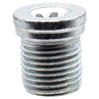
From Ford's online parts site... Magnetic Drain Plug part number: CV6Z-7A010-A FordParts.com page link for Magnetic Drain Plug Filler Plug part number: CV6Z-7A010-B FordParts.com page link for Filler Plug Web searching the part numbers may reveal lower pricing via other online sellers. Good luck!


-
Removing Side Roof Panels?
Haz replied to TonyP's topic in Glass, Lenses, Lighting, Mirrors, Sunroof (BAMR), Wipers
The Edge Workshop Manual provides a General Procedures description for Fixed Glass, but the Workshop Manual lacks a separate procedure for the removing and installing the windshield. Document download link: Fixed Glass - General Procedures - 2015 Edge Workshop Manual.pdf Online videos here and here show aftermarket firms performing windshield installations on GEN 1 Edges with their Panoramic Roof front & side trim panels in place and unaffected. One minimal risk to the roof trim panels could develop when the technician is standing upon he tdoor opening while cutting, cleaning, or applying glass sealant, and perhaps put his/her weight on the trim panel using hand, forearm, or elbow. Were you able to retrieve the blown-off trim panel, in order to determine if it was retained only by the trim clips, or if it also showed adhesive remnants on the trim panel, or if the panel wasn't recovered -- on the corresponding roof structure? Good luck! -
Perhaps you were not logged into the Forum when you attempted to access the downloads... Good luck!
-
Because you're personally doing the Recall repair work, it would be nice if your dealer found a way to grant you the half-hour of claimable Labor in FordPass Reward points... I'd expect them to submit for administering your Edge's Recall fulfillment, but not for the half-hour Labor you are supplying. I believe you mentioned previously, that they need the parts you remove, in order to technically complete their Inspection sign-off process... Good luck!


-
Document download link...TSB 22-2104 - Seat Pan Looseness, Lateral Movement, Or Clunk-Thump Noise On Turns.pdf The above-linked Technical Service Bulletin 22-2104 applies to 2015-2022 Edge, 2016-2018 MKX, 2019-2022 Nautilus, and numerous other models. New Vehicle Limited Warranty (NVLW)/Service Part Warranty (SPW)/Special Service Part (SSP)/Extended Service Plan (ESP) should cover the surprisingly simple repair procedure. Relating to the fore-aft seat movement problem... I've experienced this when the driver seat on both our 2012 & 2015 MKXs was adjusted entirely rearward upon seat track backstops. I've found that moving the seat slightly forward off the backstops eliminated the fore-aft movement problem. Our MKXs did not exhibit any lateral movement, perhaps due to their being GEN 1 models, while the above-linked TSB applies only to GEN 2 Edge/MKX/Nautilus model years. Good luck!
-
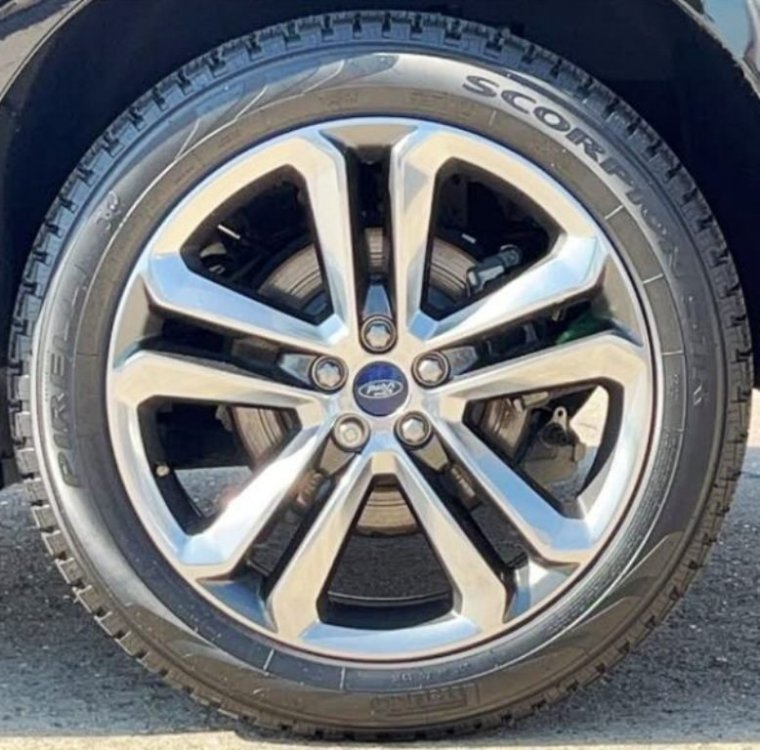
Embarking upon further research, from a prominent vehicle sales website I obtained VINs for a 2015 SEL with 18s and for a 2018 Sport with 20s. Next, I pulled Historic Vehicle Bill of Materials (HVBoM) Reports for each VIN to obtain part numbers for brake rotors and brake calipers installed on each vehicle. In addition to the original part numbers, HVBoM Reports often provide Motorcraft service replacement part references, in this case, for the brake rotors. Both Edges show Motorcraft BRRF364 vented brake rotors for the fronts and Motorcraft BRRF393 solid brake rotors for the rears. Both Edges show front brake caliper part numbers as F2GC2010 (RH) and F2GC2011 (LH), with NC suffix (2015) and NF suffix (2018); and rear brake caliper part numbers DG9C2D250 (RH) and DG9C2D251 (LH), with GD suffix (2015) and GG suffix (2018). For visual reference of caliper-to-rim clearance, the following are images of the Edges from the vehicle sales website.. 2015 Edge SEL AWD with 18" painted aluminum wheel and 245/60R18 tire (front) 2018 Edge Sport AWD with 20" alloy wheel and 245/50R20 tire (rear) Good luck!


ConnectorC240ADetailswRedHighlights-2010EdgeWorkshopManual.jpg.0e8da00fd17085e06539a0735a5c8b7f.jpg)
Diagram-2013EdgeWorkshopManual.jpg.ad540d04d41b11395c9a9836834d1345.jpg)