

Haz
-
Posts
1,251 -
Joined
-
Last visited
-
Days Won
324
Content Type
Profiles
Forums
Gallery
Everything posted by Haz
-
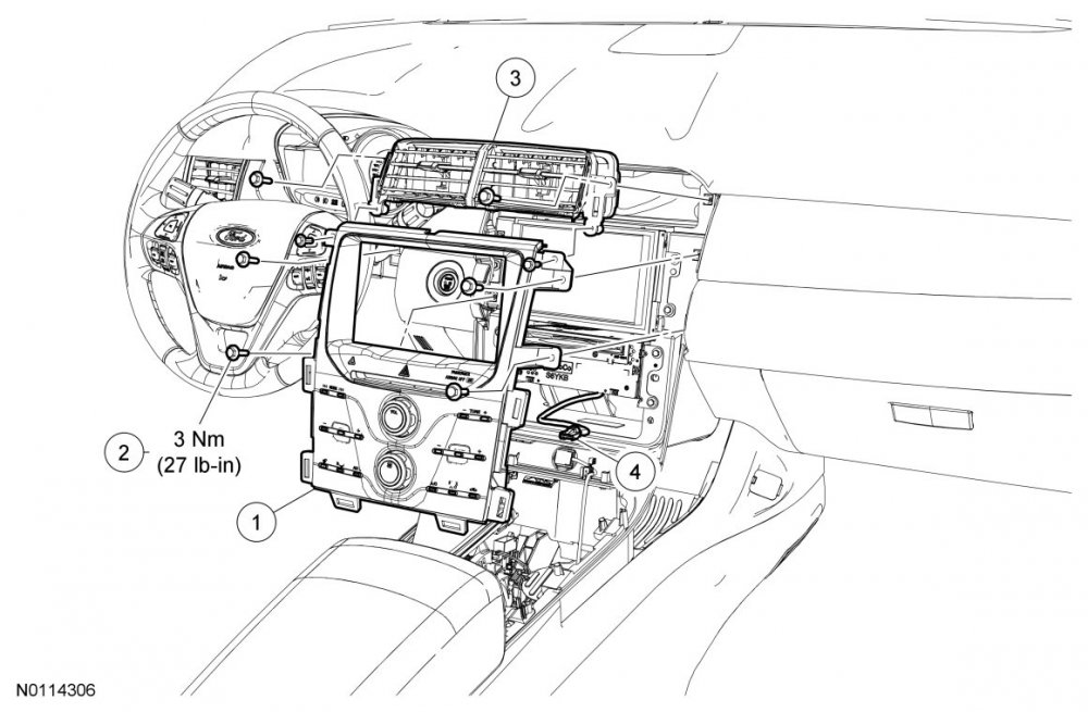
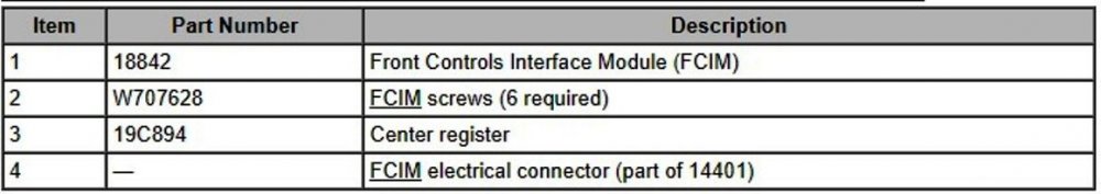
Front Control Interface Module (FCIM) illustrations and instructions from the 2013 Edge Workshop Manual, with PDF download links below... Good luck! Removal and Installation Edge Remove the LH and RH floor console upper finish moulding. For additional information, refer to the floor console exploded view. Place the transmission selector lever in neutral. NOTE: The floor console selector lever panel does not need to be removed. Remove the 4 screws, detach the 2 clips and position the floor console selector lever trim panel back. Remove the 6 Front Controls Interface Module (FCIM) screws and remove the FCIM . Disconnect the electrical connector. 5. To install, reverse the removal procedure. FCIM Enlarged Exploded View Illustration - 2013 Edge Workshop Manual.pdf Front Controls Interface Module (FCIM) Removal and Installation - 2013 Edge-MKX Workshop Manual.pdf Floor Console Finish Panels - Exploded View Illustration - 2013 Edge Workshop Manual.pdf Left & Right Upper Console Trim with Clips Illustration - 2013 Edge Workshop Manual.pdf
-
These are the challenges of buying a product on the verge of discontinuance. Gen 1 to Gen 1+ = upgrades; Gen 1+ to Gen 2 = upgrades; Gen 2 into sunset = de-contenting. According to the 2022 Order Guide, the glove box light was also deleted. I don't know the threshold of owner complaints necessary to trigger a whispered, informal Customer Satisfaction Program, but if comments here and on other Edge forums are an indicator, Ford owes late-build 2021 & all 2022 owners a no-cost air deflector installation, due to the resulting noise, vibration, and harshness (NVH) effects root-caused by the missing part. Good luck!
-
For your Edge's any Tire Pressure Monitoring System eventuality, relevant sections from the 2010 Edge Workshop Manual below as PDF download links... Tire Pressure Monitoring System (TPMS) Sensor - 2010 Edge Workshop Manual.pdf Tire Pressure Monitoring System (TPMS) Strap and Cradle - 2010 Edge Workshop Manual.pdf Tire Pressure Monitoring System (TPMS) Sensor Activation - 2010 Edge Workshop Manual.pdf Tire Pressure Monitoring System (TPMS) Sensor Training - 2010 Edge Workshop Manual.pdf Tire Pressure Monitoring System (TPMS) Diagnosis and Testing - 2010 Edge Workshop Manual.pdf Will you be using a hitch-mounted swing-away tire carrier to contain your full-size spare, like Basecamp Brooklyn (video link)? Good luck!

-
A useful illustration for me, in the future, to ask early-on if any Diagnostic Trouble Codes (DTCs) are retrievable. Good luck!
-
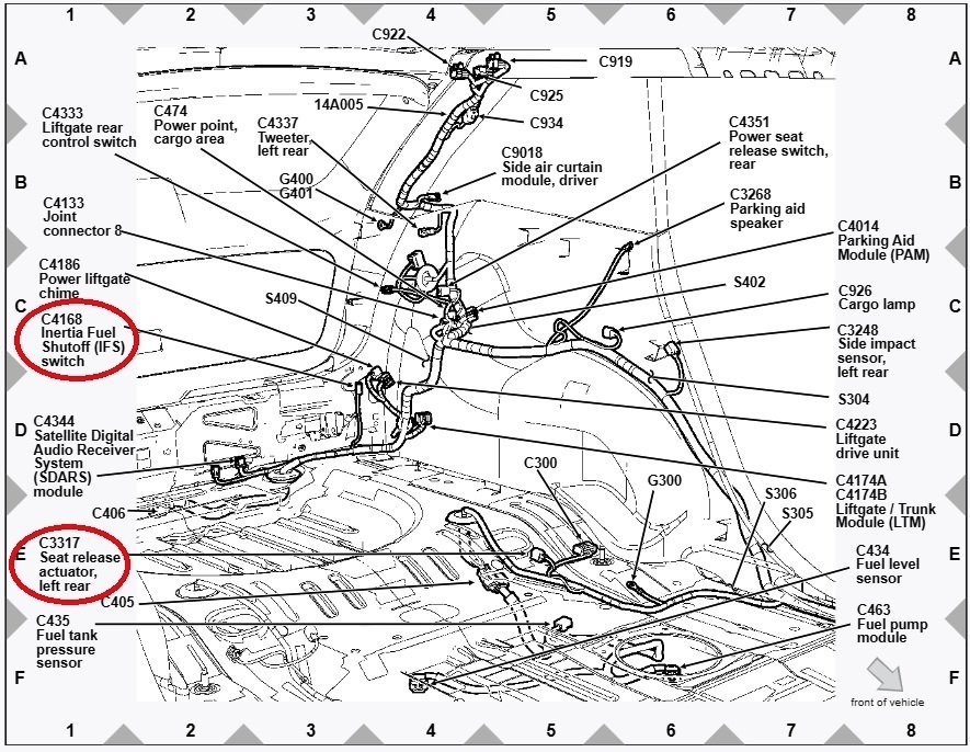
PDF download link... TSB 18-2055 - Hands-free Liftgate - Liftgate Opens-Closes When Contacting Rear Bumper With Key Present - Built On Or Before 15-Dec-2017.pdf Issue: Some 2015-2017 Edge vehicles built on or before 10-Aug-2017 and 2016-2018 MKX vehicles built on or before 15-Dec-2017, equipped with a power liftgate and the hands-free liftgate activation feature may exhibit the liftgate opening or closing when a rear door is slammed shut, or the rear fascia is contacted such as kneeling or resting a foot on the fascia while the key is present. Service action: Replace Hands-Free Liftgate Module and... Description 2015-2017 Edge: Separate And Secure Wires Includes Time To Drill Hole Remove And Install Bumper Cover 2016-2018 MKX With Factory Trailer Tow: Separate And Secure Wires Includes Time To Remove And Install Bumper Cover 2016-2018 MKX Without Factory Trailer Tow: Separate And Secure Wires Good luck!
-
Similar to enigma-2's comment, from among the 2015 Edge Workshop Manual documents... Training Sensors in a Different Order If the first sensor fails the TPMS training procedure, the BCM aborts the entire procedure. Starting the training procedure at a different wheel is a technique that can be used to determine if the remaining sensors can train to the module. This can help save time determining if one sensor is damaged, other sensors are having concerns or the BCM is experiencing training difficulties with a certain TPMS sensor location. and also, with emphasis added... TPMS Function It is not necessary to train the sensors after a tire rotation on vehicles with the same front and rear tire pressures however, the BCM cannot recognize the sensor identifiers have been moved to different positions and retains the original position information for each sensor. The manual for your TPMS Tester details its vehicle model-specific, internally guided activation procedure, but it's less detailed about performing a relearn/train procedure and whether the tool provides the same wheel-position-by-wheel-position prompts to ensure that your starting point location is always the same. Regardless of if the Tester prompts you or if you're certain you always begin with the left front, perhaps you can perform a relearn/train beginning with the left front, and take note of the tire your Edge does not receive, and the perform a second relearn/train beginning with the right front tire, in order to see if the not-received sensor location rotates virtually to a different corner. Afterward, of course, you'll need to relearn/train back to your normal starting point. Other strategies are in the previously linked... Tire Pressure Monitoring System (TPMS) - System Operation and Component Description - 2015 Edge Workshop Manual.pdf Good luck!
-
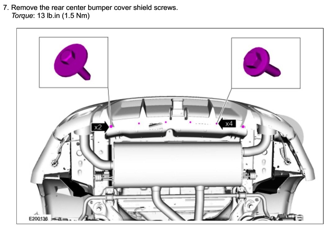
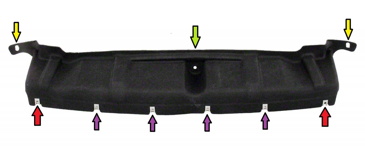
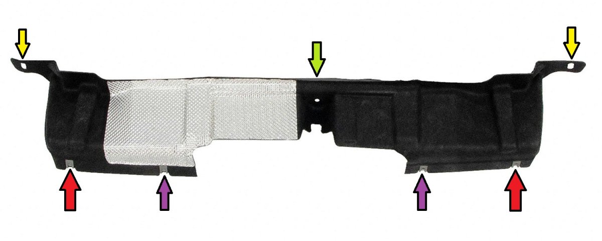
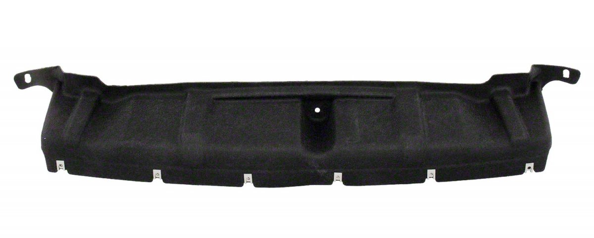
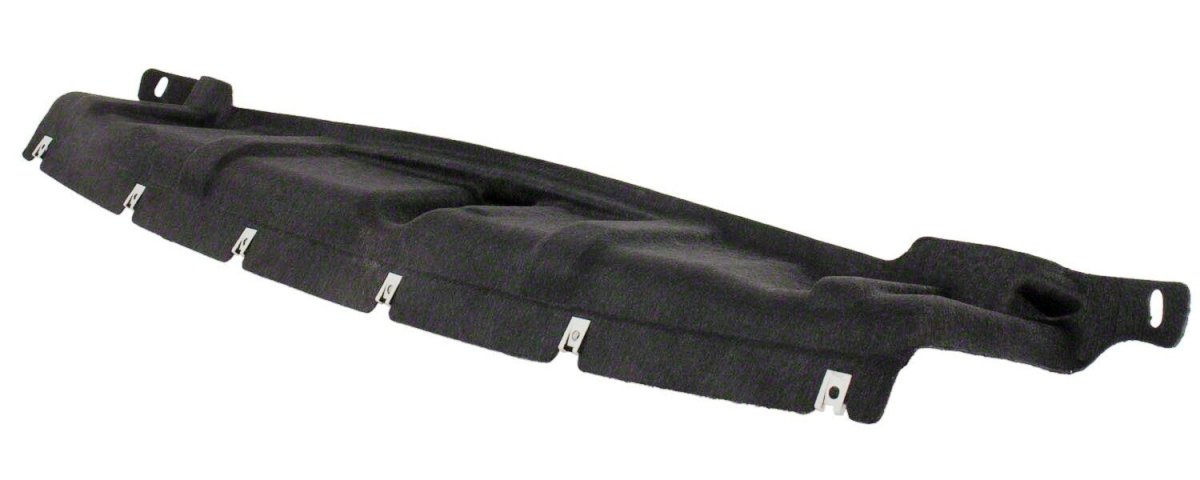
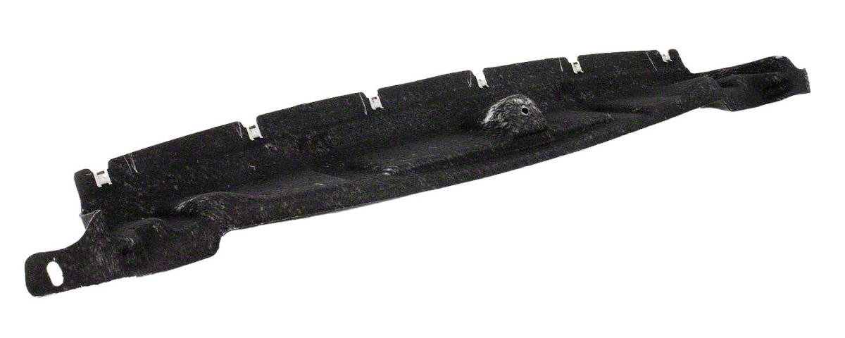
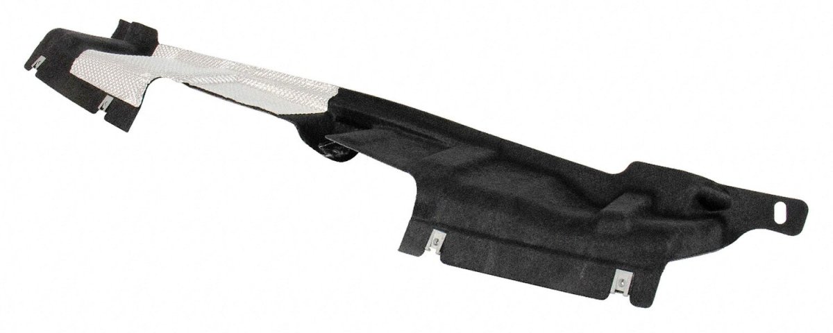
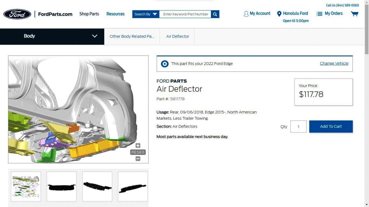
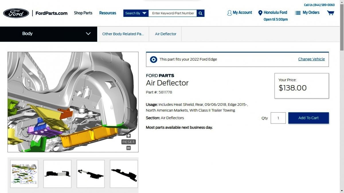
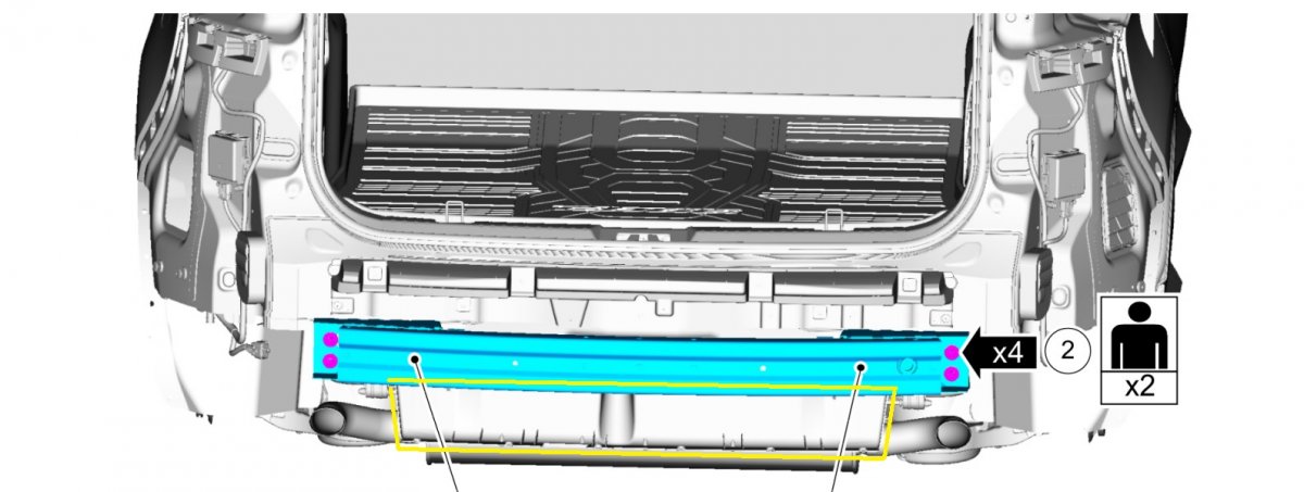
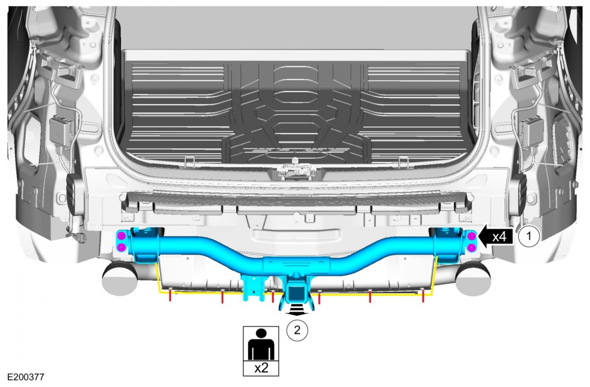
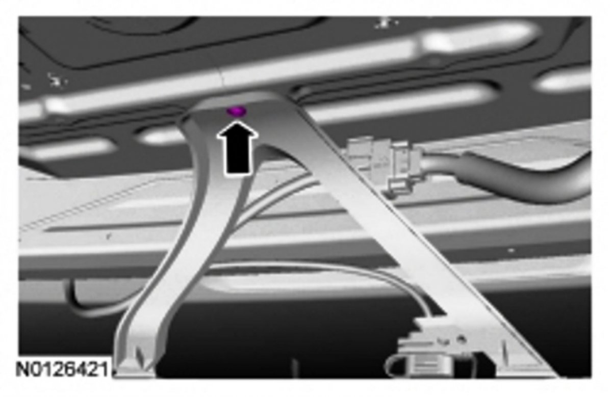
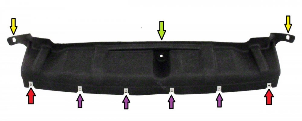
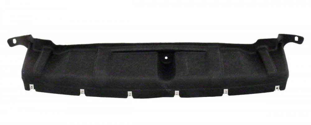
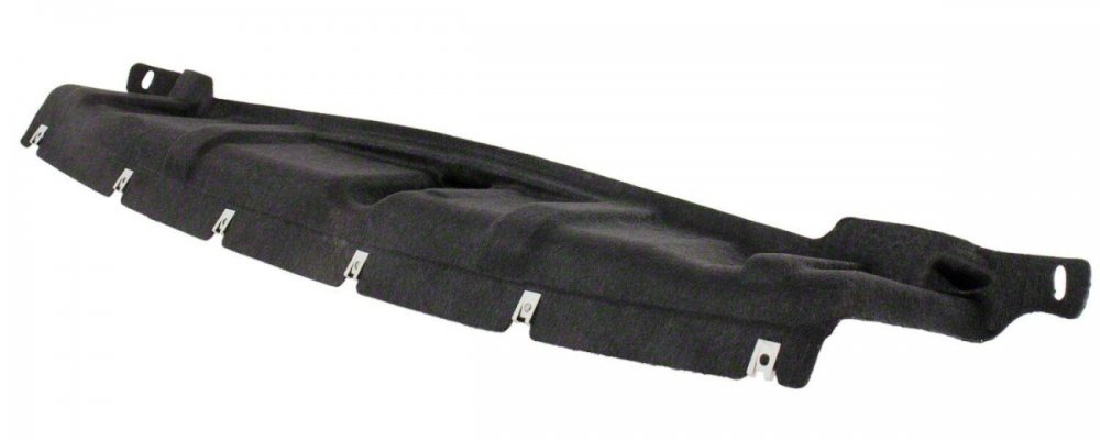
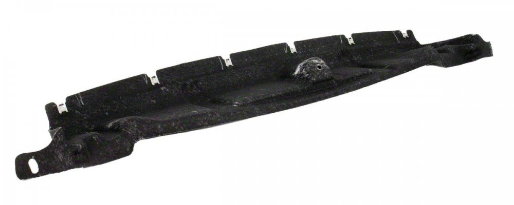
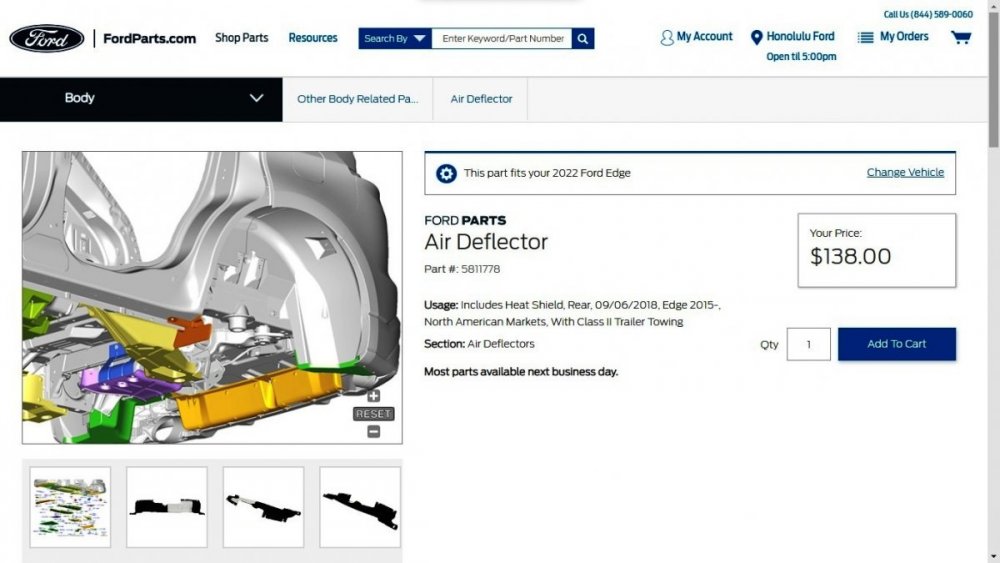
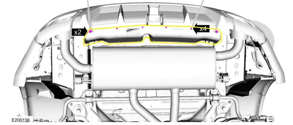
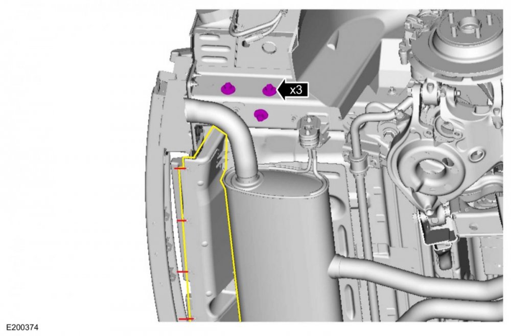
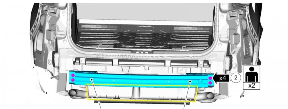
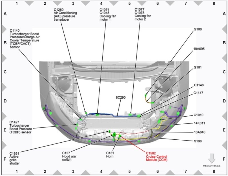
The Edge Workshop Manual shows action involving the Air Deflector/Rear Center Bumper Cover Shield occurring before removal of the Bumper Cover, so taking the Bumper Cover off is not necessary in order to install the missing part on your Edge. PDF download link to Workshop Manual document: Rear Bumper Cover - Removal and Installation - 2022 Edge Workshop Manual.pdf Additionally, the Edge Workshop Manual shows two different sizes of screws -- not push pins or clips -- are used to fasten the Air Deflector/Rear Center Bumper Cover Shield to the bottom of the bumper cover... The number of screws needed depends upon whether you are installing the 'Without Trailer Tow' (6 total screws, 2+4) or 'With Trailer Tow' (4 total screws, 2+2) version of the Air Deflector/Rear Center Bumper Cover Shield. Also notice that the likely screw hole (green arrow) which allows attachment to the underside of the cargo floor, and the oblong holes (yellow arrows) in the tabs at the left & right ends of the panel. You may want to look and see if fasteners already are already in place for those attachment points, or, if you'll need to buy additional hardware, either from where you purchase the panel or if you buy (approximately) equivalent fasteners from your local hardware store... Without Trailer Tow With Trailer Tow Good luck!


-
2015 edge FWD 2 liter front rotor size?
Haz replied to Lincoln81's topic in Brakes, Chassis & Suspension
Ford's FordParts.com site has a VIN-based search function that might be helpful before you return to your Edge... Good luck!
-
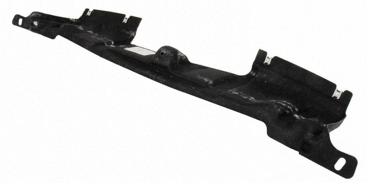
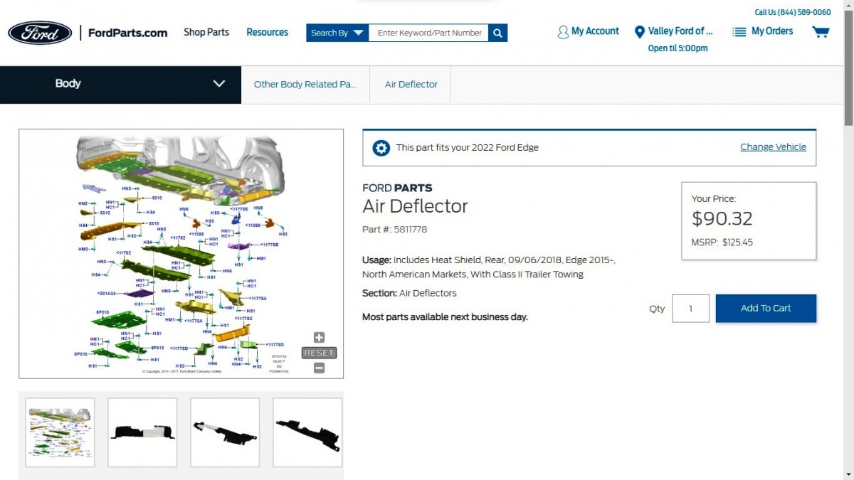
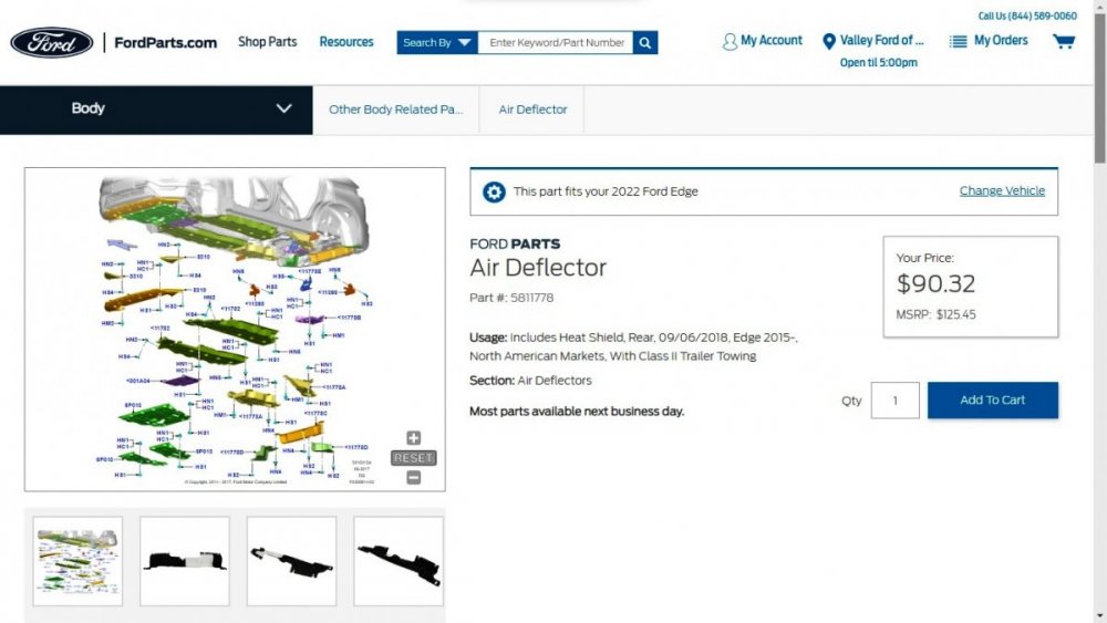
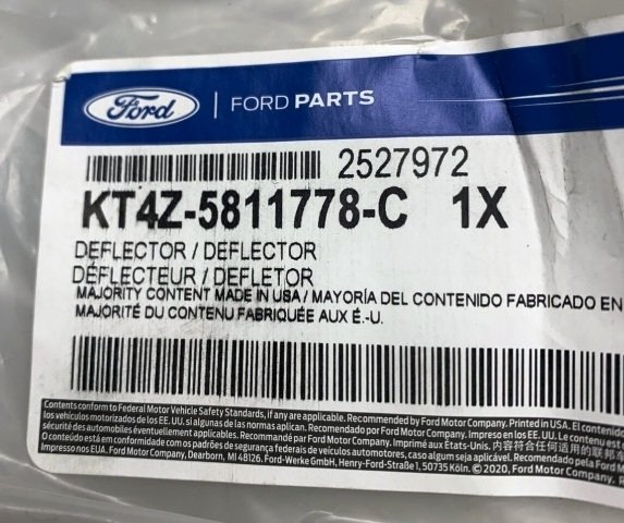
Success! Service part numbers for missing Rear Center Bumper Cover Shields for GEN 2 Edges are... Without Trailer Tow = KT4Z-5811778-C - FordParts.com listing link With Trailer Tow = KT4Z-5811778-D - FordParts,com listing link For cost reference, FordParts listings with Hawaii pricing... For cost reference, FordParts listings with Mainland pricing... Be aware that many other online sellers of Ford OEM parts offer these parts at various prices, so search around if you're looking for the best deal. Regarding the question of when Ford stopped installing Rear Center Bumper Cover Shields on Edges, I did another ten-vehicle (small sample size) survey using VINs from Titanium & ST models listed for sale online, and then pulled HVBoM reports on each to see what vehicles were built with Rear Center Bumper Cover Shields. 2021 Edges built on or before the third week of May, 2021 were fitted with Rear Center Bumper Cover Shields. 2021 Edges built on or after the fourth week of May, 2021 and all 2022 Edges were not fitted with Rear Center Bumper Cover Shields. No clarity on whether supply chain issues contributed to this, though the parts are labeled majority USA content... Much gratitude to chipdog4 for commenting on the part's composite construction , which put me onto the underbody shields grouping containing Rear Center Bumper Cover Shields. Good luck!


-
Circling back to equip you with "No Power in ON - Push Button Ignition Switch" Pinpoint tests that were touched upon in earlier post, and the wiring diagrams with supporting connector info... Good luck! No Power in ON - Push Button Ignition Switch Pinpoint Tests - 2016 Edge Workshop Manual.pdf Passive Start-Keyless Start Wiring Diagram - 2016 Edge Workshop Manual.pdf Starter Circuits Wiring Diagram - 2016 Edge Workshop Manual.pdf Start Control Unit Connector C2195 Details - 2016 Edge Workshop Manual.pdf Start Control Unit Connector C2195 Location Illustration - 2016 Edge Workshop Manual.pdf Start Control Unit Ground Circuit G200 Location Illustration - 2016 Edge Workshop Manual.pdf Start Control Unit Ground Circuit G200 Location Illustration Looking Forward - 2016 Edge Workshop Manual.pdf Body Control Module (BCM) Connector C2280G Details - 2016 Edge Workshop Manual.pdf Body Control Module (BCM) Connector C2280H Details - 2016 Edge Workshop Manual.pdf Powertrain Control Module (PCM) Removal and Installation 2.7L EcoBoost - 2016 Edge Workshop Manual.pdf Powertrain Control Module (PCM) Connector Location Illustration - 2016 Edge Workshop Manual.pdf Powertrain Control Module (PCM) Connector C175B Details - 2016 Edge Workshop Manual.pdf Powertrain Control Module (PCM) Connector C1551B Details - 2016 Edge Workshop Manual.pdf Powertrain Control Module (PCM) Connector C1551E Details - 2016 Edge Workshop Manual.pdf Powertrain Control Module (PCM) Connector C1551E Location Illustration - 2016 Edge Workshop Manual.pdf
-
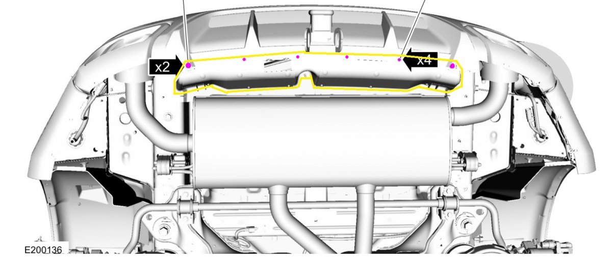
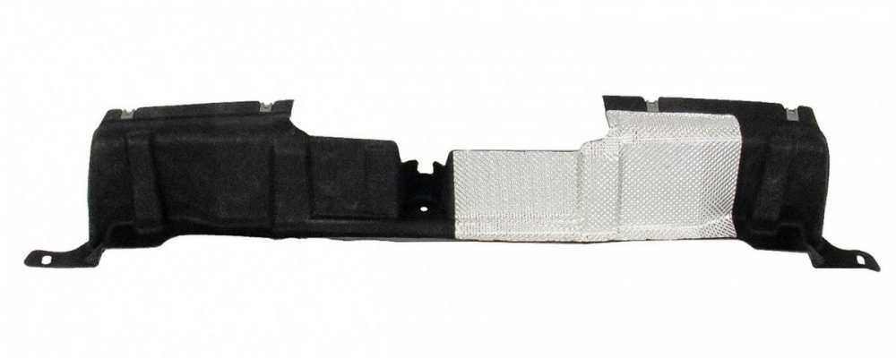
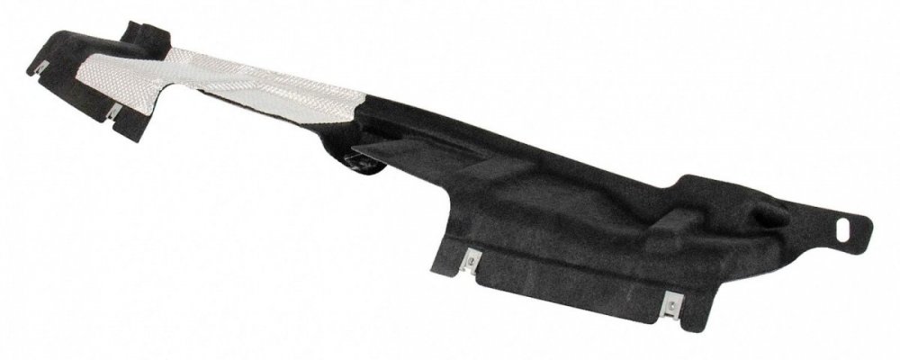
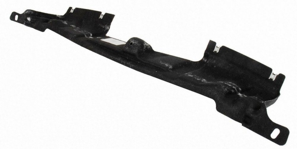
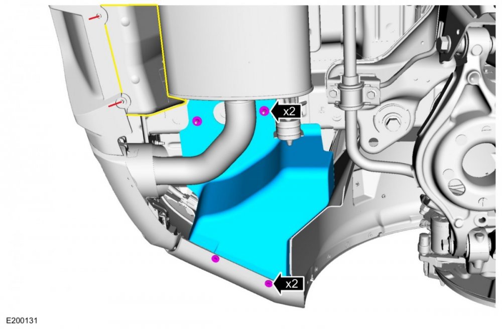
So, absent feedback from other GEN 2 Edge owners, I'll offer the results of my online research. Edge Workshop Manuals from model years 2015-to-2022 show a panel, the Rear Center Bumper Cover Shield, which attaches to the bottom of the bumper cover with six screws, extends forward then upward between the muffler and the bumper bar or factory hitch bar, with the top leg screwed to the underside of the cargo area floor structure. The following Workshop Manual images have the pictured Rear Center Bumper Cover Shield outlined in yellow... I searched online OEM parts-sellers and Ford's own FordParts.com, and no reference to the Rear Center Bumper Cover Shield exists, including among illustrations of rear bumper cover buildups. I then pulled VINs for all GEN 2 model years from Edge's equipped with the Tow Package currently offered for sale online, and for each VIN, I ran Historical Vehicle Bill of Material reports, which list parts numbers of components specifically installed on each vehicle. Again, no reference to the Rear Center Bumper Cover Shield existed. If your zip-tie tethers to your rear bumper cover prove unsatisfying, you could take the Workshop Manual document from the PDF download link below, to your local dealer's Parts Department to see if their resources show the Rear Center Bumper Cover Shield. Rear Bumper Cover - Removal and Installation - 2022 Edge Workshop Manual.pdf As an alternative to this potential ghost part that escaped removal from GEN 2 Workshop Manual illustrations, you could fashion a V-shaped brace out of sheet plastic or other suitable material, like the brace molded with a live-hinge into the bottom edge or rear bumper covers of GEN 1+ Edges, which attaches with a single screw to the underside of the cargo area floor, between the muffler and the bumper bar or hitch bar, which is a fairly compact area... Aloha!


-
TECHNICAL SERVICE BULLETIN 2021 Edge/Nautilus - Various SYNC4 Concerns 22-2062 25 February 2022 Model: Ford 2021 Edge Lincoln 2021 Nautilus Issue: Some 2021 Edge/Nautilus vehicles may experience one or more of the following symptoms: Android Auto connection concerns, Apple CarPlay connection concerns, Information and entertainment screen freezing/locking up, windows media audio (WMA) files not playing properly from a universal serial bus (USB) device, intermittent blank information and entertainment screen, Bluetooth connectivity concerns, incorrect Owner's Manual language for French, frozen or delayed response for touch screen improvements. This may be due to the software in the accessory protocol interface module (APIM). To correct the condition, follow the Service Procedure to reprogram the APIM. NOTE: The APIM software update that addresses the symptom listed in this bulletin may have been sent via Ford Power-Up software updates delivered over-the-air (OTA) to connected vehicles that have automatic updates enabled through the SYNC 4 screen. Enter the vehicle identification number (VIN) in Professional Technician System (PTS) and check the OTA Dashboard under the Connected Vehicle tab for OTA update history. If an update to the APIM has successfully completed recently and the customer is reporting the symptoms are no longer present, this article may not apply. Action: Follow the Service Procedure steps to correct the condition on vehicles that meet all of the following criteria: • 2021 Edge/Nautilus • At least one of the following: - Android Auto connection concerns - Apple CarPlay connection concerns - Information and entertainment screen freezing/locking up - WMA files not playing properly from a USB device - Intermittent blank information and entertainment screen - Bluetooth connectivity concerns - Incorrect Owner’s Manual language for French - Frozen or delayed response for touch screen improvements Warranty Status: Eligible under provisions of New Vehicle Limited Warranty (NVLW)/Service Part Warranty (SPW)/Special Service Part (SSP)/Extended Service Plan (ESP) coverage. Limits/policies/prior approvals are not altered by a TSB. NVLW/SPW/SSP/ESP coverage limits are determined by the identified causal part and verified using the OASIS part coverage tool. Labor Times Description Operation No. Time 2021 Edge/Nautilus Check Software Reprogram APIM (Do Not Use With Any Other Labor Operations) 222062A 1.5 Hrs. 2021 Edge/Nautilus Check Software Reprogram GWM and APIM (Do Not Use With Any Other Labor Operations) 222062B 1.8 Hrs. Repair/Claim Coding Causal Part: 14G670 Condition Code: 04 Service Procedure NOTE: Ask the customer to bring their spare key fob to assist in the Ford Diagnosis and Repair System (FDRS) programming. NOTE: The gateway module (GWM) must be at the latest software level before the APIM update can be performed. Updated APIM software will not show as being available in FDRS until the GWM has been successfully updated. 1. Connect the vehicle communications module (VCM) II, vehicle communication and measurement module (VCMM) or later level to the vehicle data link connector (DLC) and the diagnostic scan tool USB port. Start a vehicle session with the FDRS and select the toolbox tab to see the available software updates. 2. Is a GWM software update available? (1). Yes - proceed to Step 3. (2). No - proceed to Step 4. 3. Update the GWM using the latest version of FDRS. Refer to Workshop Manual (WSM), Section 418-01A for Module Reprogramming. (1). Connect a battery charger to the 12 volt battery. NOTE: A blank 32GB or larger USB flash drive is required for GWM update. Make sure the USB flash drive being used is formatted correctly. To see the available drives, hold down the Windows icon keyboard key and press the E keyboard key. Right click on the USB flash drive and select Properties. If File System under the General tab is not exFAT, the drive must be formatted. To format the USB flash drive, right click on the USB flash drive, select Format, select exFAT for the File System, and select Default Allocation Size for the Allocation Unit Size. De-selecting Quick Format is not necessary and will result in a lengthier operation. (2). Using the FDRS, reprogram the GWM by selecting GWM - Gateway Module A (GWM) Software Update. Follow all on-screen instructions carefully. (3). When prompted, connect the USB flash drive to the FDRS diagnostic scan tool. NOTE: It may take up to 30 seconds for the vehicle to recognize the USB flash drive. (4). When prompted by the FDRS, safely remove/eject the USB flash drive from the FDRS diagnostic scan tool. Close all of the vehicle's doors and plug in the USB flash drive into the USB media hub in the vehicle. The vehicle will recognize the USB flash drive and allow up to 10 minutes for the update to start automatically. (5). Next the SYNC touchscreen will prompt to restart the vehicle. With the USB flash drive still in the vehicle, turn the vehicle ignition OFF and keep all of the vehicle's doors closed and allow the vehicle to power down for at least 5 minutes. The SYNC touchscreen may stay turned on for a few more seconds after turning off the vehicle. (6). With the USB flash drive still in the vehicle and after waiting 5 minutes with all of the vehicle's doors closed, turn the vehicle ignition ON. Allow the vehicle to power on and look for a Update Successful pop up in the vehicle SYNC touchscreen. If a Restart Is Required message pops up again, this may be due to having the vehicle's doors open when turning off the ignition. (7). Once the pop-up stating Update Successful appears in the SYNC screen, select Close, remove the USB flash drive from the USB media hub and connect it to the FDRS diagnostic scan tool, and select OK on the FDRS. This initiates the remaining automated configuration steps and reports the GWM assembly, vehicle interface processor (VIP), calibration, customer interface processor (CIP), and application software levels to the Ford online database. Failure to follow this step results in an inaccurate database as well as omitted, improperly installed, or improperly configured applications (features) such as navigation (if equipped). It is normal for the GWM to reset during this step. 4. If a GWM software update was performed, re-run the network test on the FDRS. Is an APIM software update available? (1). Yes - proceed to Step 5. (2). No - this article does not apply. Refer to WSM, Section 415-00. NOTE: A blank 64GB or larger USB flash drive is required for APIM software update. Make sure the USB flash drive being used is formatted correctly. To see the available drives, hold down the Windows icon keyboard key and press the E keyboard key. Right click on the USB flash drive and select Properties. If File System under the General tab is not exFAT, the drive must be formatted. To format the USB flash drive, right click on the USB flash drive, select Format, select exFAT for the File System, and select Default Allocation Size for the Allocation Unit Size. Make sure the Quick Format box is selected. If it is not selected, it will result in a lengthier operation. 5. Verify a battery charger connected to the vehicle's 12 volt battery. Set the charger to maintain 12.6-13.6 volts. 6. Close all doors on the vehicle. Locking the latch mechanically while the door is open will simulate a closed door. 7. Download and run the APIM Software Update application on the FDRS and follow the on-screen prompts. If any error conditions are experienced during programming, refer to WSM Section 418-01A > General Procedures > Module Programming for the Error Condition Table. NOTE: Downloading software to the FDRS may take up to 1 hour and saving that data to the USB flash drive may take up to 30 minutes. During this time, no interaction is needed with the FDRS. (1). Follow the FDRS prompts and install the USB flash drive into the vehicle. Wait 5 minutes for the updating prompts to show up in the sync screen. NOTE: It may take up to 5 minutes for the vehicle to recognize the USB flash drive. All doors must remain closed until the SYNC screen prompts a restart is required. To view the progress, you can drop down the updating screen in the sync screen. It make take up to 20 minutes for the vehicle to download all of the data from the USB flash drive. (2). When the USB has downloaded to the vehicle, the touchscreen indicates a message for Restart Required. The ignition needs to be turned off for 10 minutes. Keep all vehicle doors closed during this key off time. (3). After the 10 minutes and with all of the vehicle's doors closed, start the vehicle and allow another 5 minutes for the Update Successful message to appear in SYNC screen. Once the Update Successful message appears, the USB flash drive may be removed, and the doors opened. A popup indicating the software has already been installed in the vehicle may show up in the SYNC screen instead of the Update Successful message. This message should be treated as a response that the APIM software has been updated. (4). Return the USB thumb drive to the FDRS and follow the on-screen prompts to complete the procedure. PDF download link to the document... TSB 22-2062 - 2021 Edge-Nautilus - Various Sync Concerns - February 25, 2022.pdf
-
Sync 4A disasters, am I the only one?
Haz replied to Xfire's topic in Audio, Backup, Navigation & SYNC
In late February, Ford issued a Technical Service Bulletin exclusively for 2021 Edge/Nautilus to address a laundry list of Sync 4 problems that surfaced in vehicles lacking an over-the-air APIM/Sync Module update. Determining if the TSB applies is accomplished by looking up the vehicle's OTA Update Dashboard for the most recent APIM/Sync Module update timing. You might try contacting your dealer and have them pull up your Edge's APIM/Sync Module update history & OASIS Sync Service histories, to see if this TSB service action might solve your Edge's Sync troubles. If the TSB applies, the repair requires a visit to the dealership with the vehicle and both keyfobs. Below is a PDF download link to the document... TSB 22-2062 2021 Edge-Nautilus Various Sync Concerns - February 25, 2022.pdf Good luck! -
I've been working with Hawie offline. We determined that his Edge's liftgate glass had been previously broken and, unfortunately, was replaced with a unit lacking the in-glass antenna grid(s). He researched adding an aftermarket stick-on antenna grid to the inside of the replacement glass, but subsequently found online feedback saying rear window defroster usage would create radio interference. He experimented using a simple length of wire inside the window aperture and his Edge did gain some local station reception. At last report, he was pursuing an exterior-mount aftermarket antenna as a long-term solution, which he might eventually provide us an update on. Good luck!
-
need more power on the wireless charging pad
Haz replied to ben senise's topic in Audio, Backup, Navigation & SYNC
From the 2020 Edge Workshop Manual... Wireless Accessory Charging Module (WACM) - Overview The WACM is a 5 Watt wireless power transmitter designed to energize a secondary coil that may already be equipped in a secondary device (smart phone), or as an added accessory (wireless charging phone sleeve). The WACM supports wireless charging of the Wireless Power Consortium’s (WPC) Qi, pronounced “Chee". The WACM is a powered at all time node from fused battery and performs network management on HS-CAN3 . Wireless charging status is provided as a CAN signal on the HS-CAN3 . The BCM provides a protected switch to battery input to the WACM when an interior passive key search is in progress to disable the wireless charging feature. This is to prevent possible interference with the passive key when placed in close proximity to the WACM during a charge session of a secondary device. A redundant CAN signal is also sent by the BCM in addition to the protected switch to battery input. Good luck! -
Images from the 2021 Edge Workshop Manual... Good luck!
-
Park outdoors: Ford expands recall for possible engine fires
Haz replied to 1004ron's topic in Articles, News & Reviews
I appreciate you quoting from the photo caption, which is unrelated to underhood fire risk and lacks any need to park involved vehicles outside, because that Safety Recall 22S43 has been previously detailed in the Forum, and affected Edge owners will benefit from your reminder... The 'Possible Engine Fires' headline and underhood fire topic of the article relates to Safety Recalls 22S36 & 22S48, which apply to 2021 Expedition and Navigator, as well as Safety Recall 22S47 which applies to 2021/2022 Corsair and 2022 Maverick. Good luck! -
Aftermarket hitch and drilling
Haz replied to thesavo's topic in Cargo, Hauling, Roof Racks & Towing
Per the instructions linked below, the fasteners removed from the bumper bar may be retained and reused for the hitch installation... 2015-2018 Edge Factory No-Drill Trailer Hitch Installation Instructions 2.pdf Good luck! -
Park outdoors: Ford expands recall for possible engine fires
Haz replied to 1004ron's topic in Articles, News & Reviews
It is worth noting that Edge, MKX, and Nautilus are not involved in the described headlined Recalls. Good luck! -
From the 2015 Edge Workshop Manual, as PDF download links below... Tire Pressure Monitoring System (TPMS) - System Operation and Component Description - 2015 Edge Workshop Manual.pdf Tire Pressure Monitoring System (TPMS) - Diagnosis and Testing - 2015 Edge Workshop Manual.pdf Tire Pressure Monitoring System (TPMS) - Component Location - 2015 Edge Workshop Manual.pdf The Workshop Manual does not provide diagnostic procedures specific to the Radio Transceiver Module (RTM), but does offer evaluation of the RTM in the context of the involved component -- in this case, within the TPMS diagnostics linked above. If your diagnostic efforts progress to requiring electrical connector details, just let me know and I will provide them. If your efforts progress to the RTM... Radio Transceiver Module (RTM) - Removal and Installation - 2015 Edge Workshop Manual.pdf Headliner Lowering - 2015 Edge Workshop Manual.pdf Good luck!
-
Below is a PDF download link to a job aid on parasitic current draw analysis... Parasitic Battery Drain Job Aid.pdf Good luck!
-
'Notice To Dealers' letter updated; Owner Refunds information added, Sample Letter to Owners added, and Recall Repair Technical Info added. Good luck!
-
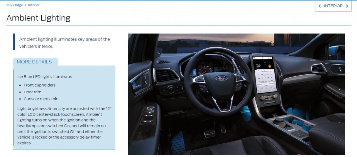
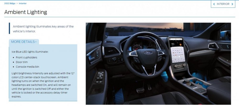
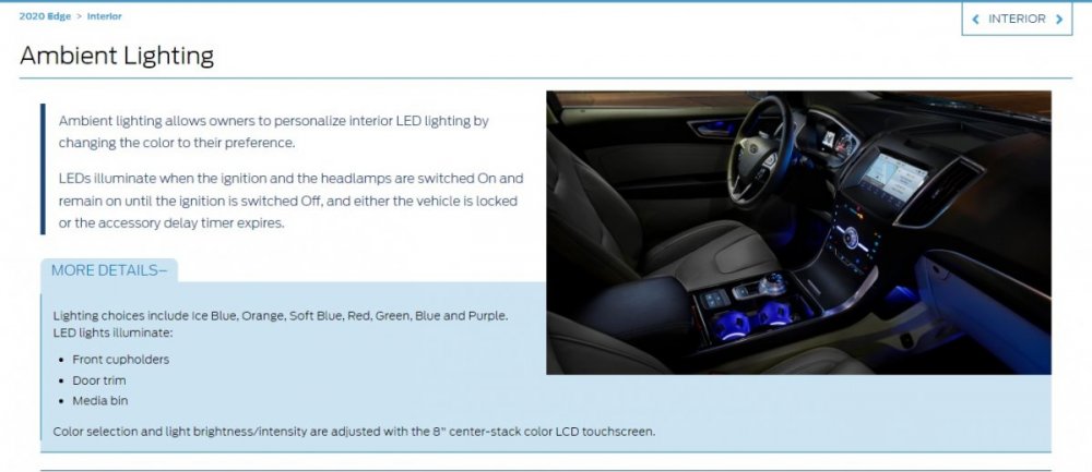
An online resource for dealership sales reps indicates Ice Blue as the only Ambient Light color on 2022 & 2021 Edges... ...and it shows 2020 Edge being the last model year having multi-color Ambient Light selection... According to Helm Inc, Ford has not yet released to them the 2022 Edge Workshop Manual. Hopefully, they are correcting issues like the Ambient Light feature in the 2022 Edge edition, which Helm will eventually market on a CD. Omar302's encouragement to report the unreliable 'On' Ambient Lights setting to your dealership Service department is worthwhile. If they feed the issue's existence back up the chain, through the Technical Assistance Center, a corrective software update could be developed. As an example -- and for any GEN 1+ Edge/MKX owners coming to this discussion with a comparable issue -- below is a PDF download link to TSB 14-0175... TSB 14-0175 - 2011-2014 Edge & MKX - Ambient Lighting Defaults to White or Ice Blue After Cycling Ignition Switch.pdf Good luck!
-
From the 2022 Edge Workshop Manual... Ambient Lighting The ambient lighting subsystem consists of the BCM , and the Light Emitting Diodes (LEDs) located within the floor console, front and rear door panels, instrument panel and front and rear footwell areas. The ambient lighting is operational when the ignition is in any state other than OFF (the exception is when it is used in conjunction with the illuminated entry/exit features), the headlamps are on and the outside ambient light level is low. The BCM provides the voltage to the ambient lighting system, while the touchscreen ( FDIM ) is used to cycle through the different color variations or turn the ambient lighting feature on or off. A LIN circuit is routed from the BCM to all of the Light Emitting Diodes (LEDs). There are 3 Light Emitting Diodes (LEDs) (red, blue and green) housed within each LED assembly. By illuminating various color combinations, the Light Emitting Diodes (LEDs) are able to produce different colors of ambient light. The APIM uses software to monitor the user interface from the touchscreen. Based on the ambient lighting system selections made using the touchscreen, the APIM sends ambient light color request and ambient light intensity request messages over the communication network for color and brightness settings. The BCM retains the last color and brightness setting between uses. I looked for Ambient Lighting TSBs and SSMs, but there are none. Perhaps the next OTA update will correct it. Good luck!
-
Good thought, enigma-2... Good luck!