

Haz
-
Posts
1,251 -
Joined
-
Last visited
-
Days Won
324
Content Type
Profiles
Forums
Gallery
Everything posted by Haz
-
No brake lights and can't shift out of park
Haz replied to myf16's topic in Brakes, Chassis & Suspension
Below are PDF download links to relevant sections of the 2009 Edge Workshop Manual... If you require specific connector details, let me know and I will provide you the information. Good luck! Turn Signal-Stop-Hazard Lamps Wiring Diagram 1 - 2009 Edge Workshop Manual.pdf Turn Signal-Stop-Hazard Lamps Wiring Diagram 2 - 2009 Edge Workshop Manual.pdf Stop Lamps Diagnosis and Testing - 2009 Edge Workshop Manual.pdf Stop Lamps Switch Removal and Installation - 2009 Edge Workshop Manual.pdf Brake-Shift Interlock Description and Operation - 2009 Edge Workshop Manual.pdf -
Below are PDF download links to relevant sections of the 2014 Edge Workshop Manual, relating to Power Liftgate operation, diagnostics including Diagnostic Trouble Code (DTC) and Symptom lists, wiring diagrams, and several major component removal and installation procedures. If your diagnostic efforts progress to steps requiring specific connector details beyond what the document offers, let me know and I will provide the connector information. Good luck! Power Liftgate Diagnosis and Testing - 2014 Edge Workshop Manual.pdf Power Liftgate Wiring Diagram - Page 1 - 2014 Edge Workshop Manual.pdf Power Liftgate Wiring Diagram - Page 2 - 2014 Edge Workshop Manual.pdf Power Liftgate Wiring Diagram - Page 3 - 2014 Edge Workshop Manual.pdf Power Liftgate Wiring Diagram - Page 4 - 2014 Edge Workshop Manual.pdf Power Liftgate Wiring Diagram - Page 5 - 2014 Edge Workshop Manual.pdf Power Liftgate Initialization - 2014 Edge Workshop Manual.pdf Power Liftgate Motor Removal and Installation - 2014 Edge Workshop Manual.pdf Liftgate-Trunk Module (LTM) Removal and Installation - 2014 Edge Workshop Manual.pdf
-
2018 Ford Edge No Tweeter Wiring Rear Door
Haz replied to bhamraS97's topic in Audio, Backup, Navigation & SYNC
Below as PDF download links are rear door speaker wiring diagram, speaker connector details, speaker removal & installation procedures, and in case you need it, door panel removal and installation procedures. The wiring diagram and connector detail appear to show the tweeter wiring jumps up from the door speaker connector. If you cannot locate the unconnected tweeter harness inside the door cavity, you could probably order the appropriate pigtail connector kit or use generic audio connector pins and the proper gauge wire indicated in the connector details to create your own tweeter harness extension from the door speaker connector. Good luck! Edge Sony Rear Door Audio Wiring Diagram - 2018 Edge Workshop Manual.pdf Rear Door Speaker Left Hand Driver's Side - Connector C702 - 2018 Edge Workshop Manual.pdf Rear Door Tweeter Speaker Left Hand-Driver's Side - Connector C730 Details - 2018 Edge Workshop Manual.pdf Rear Door Speaker Right Hand Pass Side - Connector C802 Details- 2018 Edge Workshop Manual.pdf Rear Door Tweeter Speaker Right Hand-Pass Side - Connector C830 Details - 2018 Edge Workshop Manual.pdf Rear Door Audio Connector Locations Left Hand-Driver's Side - 2018 Edge Workshop Manual.pdf Rear Door Audio Connector Locations Right Hand-Pass Side - 2018 Edge Workshop Manual.pdf Rear Door Speaker LH Removal and Installation - 2018 Edge Workshop Manual.pdf Rear Door Speaker RH Removal and Installation - 2018 Edge Workshop Manual.pdf Rear Door Tweeter Speaker Removal and Installation - 2018 Edge Workshop Manual.pdf Rear Door Trim Panel Removal and Installation - 2018 Edge Workshop Manual.pdf Rear Door Window Control Switch Removal and Installation - 2018 Edge Workshop Manual.pdf -
SSM 50975 2017-2022 Various Ford And Lincoln Vehicles - Deep Sleep Mode Notification In FordPass® And/Or LincolnWay® Cell Phone Apps Some 2017-2022 Ford/Lincoln customers may experience a notification in the FordPass®/LincolnWay® app indicating Vehicle Has Entered Deep Sleep Mode. This occurs when the vehicle has not been started for 14 consecutive days, battery voltage is at/below 9.5 volts or the body control module (BCM) 12 volt battery state of charge (SOC) drops below 50%. A warning may also set if the telematic control unit (TCU) has received an over the air update. The TCU powers down all communication when in this mode and app features are disabled. Manually start the vehicle to wake if from mode. More information is located in the app under: Account > Help > search 'Deep Sleep' in the entry box. If the condition remains, check the BCM 12v SOC. If the SOC does not change after charging the battery or after BMS reset is performed, continue with normal battery and/or BMS sensor diagnostics.
-
So, Hawaii is Ford Dealer Paradise too. Aloha!
-
Posting this to provide historical reference to timing of under-hood insulation discontinuance... SSM 50313 2019-2022 Edge - Under Hood Insulation No Longer Equipped - Built On Or After 7-Feb-2019 2019-2022 Edge SE and SEL vehicles built on or after 7-Feb-2019 and Edge ST and Titanium vehicles built on or after 2-May-2019 are no longer equipped with an insulation panel on the underside of the hood. The vehicle is not misbuilt. The addition of any parts is not a warrantable repair. Do not submit a claim for this condition.
-
Kclonn: Just noticed this, from November 30, 2021, regarding risk to the prospect of your dealer providing free under-hood insulation... SSM 50313 2019-2022 Edge - Under Hood Insulation No Longer Equipped - Built On Or After 7-Feb-2019 2019-2022 Edge SE and SEL vehicles built on or after 7-Feb-2019 and Edge ST and Titanium vehicles built on or after 2-May-2019 are no longer equipped with an insulation panel on the underside of the hood. The vehicle is not misbuilt. The addition of any parts is not a warrantable repair. Do not submit a claim for this condition. Good luck!
-
Welcome to the Forum! Input you Edge's VIN into this Ford website to determine if your Edge has any outstanding Field Service Actions, looking especially for 13N02 Brake Booster Extended Warranty coverage, which may be expiring soon for many vehicles, based upon new vehicle purchase date. If 13N02 is not listed, then your Edge has already received a new Brake Booster after the failure of the originally-installed component, so that's good news. The following is a PDF download link to the document sent to original owners - 13N02 - Brake Booster Warranty Extension - 2010 thru 2013 Edge and MKX.pdf Good luck!
-
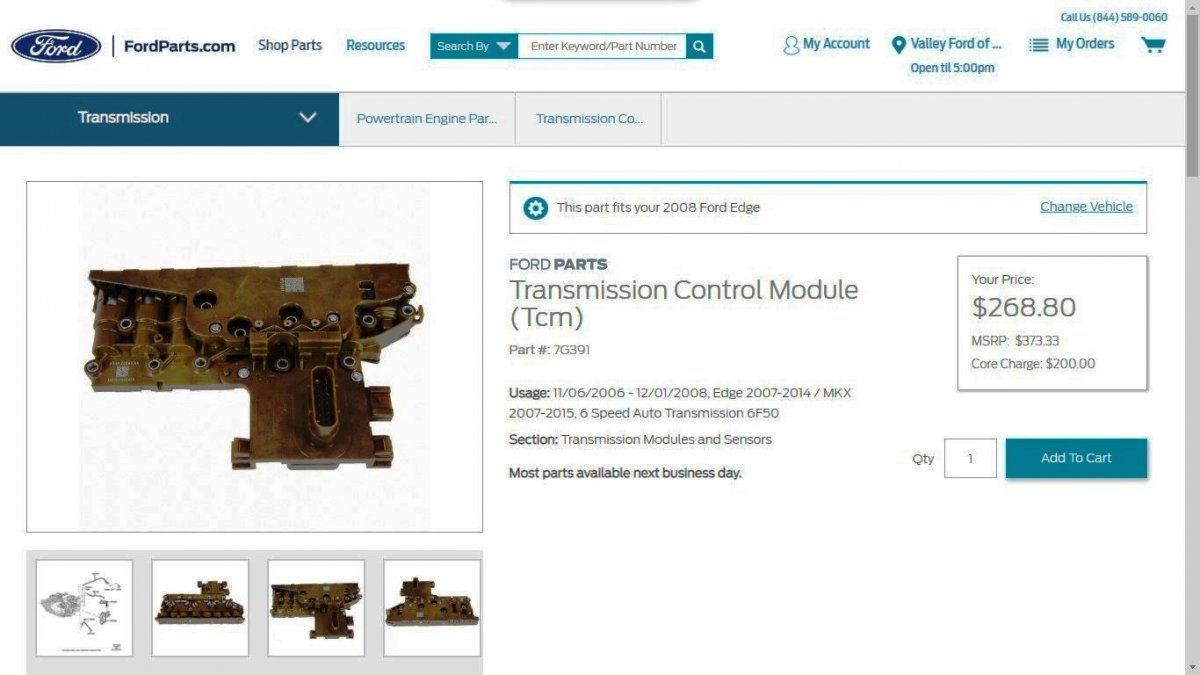
While the below FordParts web page describes it as 'Transmission Control Module' for (GEN1/GEN1+) 6F50 transmissions, Factory Service Manuals thru 2022 term it as 'Solenoid Body', with the 2008 Edge Workshop Manual providing this programming and functional traits description: Solenoid Body NOTICE: If the solenoid body identification and strategy does not match the solenoid body information in the Powertrain Control Module (PCM), transaxle damage or driveability concerns can occur. The solenoid body contains 7 solenoids, 5 shift solenoids [Shift Solenoid A (SSA) , Shift Solenoid B (SSB) , Shift Solenoid C (SSC) , Shift Solenoid D (SSD) and Shift Solenoid E (SSE)]. TCC solenoid and LPC solenoid. The Transmission Fluid Temperature (TFT) is also located in the solenoid body. The solenoid body is serviced as an assembly. The solenoid body has a unique strategy data file that must be downloaded to the PCM. there is a 7-digit solenoid body identification and a 13-digit solenoid body strategy for each solenoid body. Anytime a new solenoid body is installed or the transaxle is installed, the scan tool must be used to get the solenoid body strategy data file and download it into the PCM. If the PCM is replaced and the PCM data can not be inhaled or exhaled, the solenoid body identification and solenoid body strategy must be downloaded into the PCM. Shift Solenoid A (SSA) , Shift Solenoid B (SSB) , Shift Solenoid C (SSC) , Shift Solenoid D (SSD) and Shift Solenoid E (SSE) Five shift solenoids are used for electronic shift scheduling. The 5 solenoids are located in the solenoid body. SSA , SSB , SSC and SSD are Variable Force Solenoid (VFS) . SSE is an ON/OFF shift solenoid. Shift solenoids SSA , SSB , SSC , SSD and SSE provide selection of 1st through 6th gears and reverse by controlling the pressure of the shift valves. SSA and SSC are normally low-pressure solenoids. Pressure increases as the PCM activates the solenoid. SSB and SSD are normally high-pressure solenoids. Pressure decreases as the PCM activates the solenoid. SSE is normally closed and opens when the PCM activates the solenoid. The solenoids are activated by the PCM controlling current flow at the solenoid ground circuit, this is known as ground side switching. Thanks for your question, which provided me this learning opportunity. Good luck!

-
SSM 50970 2021-2022 Edge - USB Drive Not Recognized During APIM Software Update Or Center Display Screen Not Acknowledge USB Programming Has Started Some 2021-2022 Edge vehicles may exhibit a concern during an accessory protocol interface module (APIM) software update where the vehicle fails to recognize the universal serial bus (USB) drive or center display screen does not acknowledge USB programming has started. If the Ford Diagnosis and Repair System (FDRS) application titled Module Update Repair has been performed previously but the vehicle fails to indicate that the USB programming has started, inform customers that they can continue to drive the vehicle and engineering is currently working on a solution, expected by the end of August 2022. Monitor OASIS for additional information and schedule service appointments for customers once the repair becomes available.
-
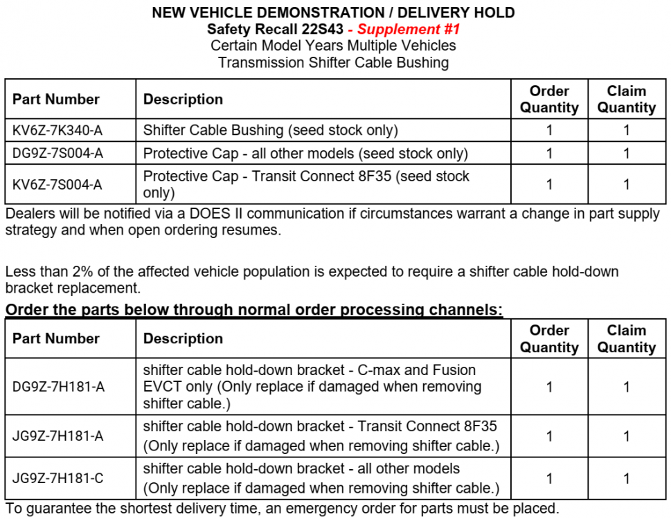
Below is PDF download link to entire Dealer Bulletin document... Safety Recall 22S43 - Dealer Bulletin - Supplement 1 - August 1, 2022.pdf Good luck! Download link updated to Supplement 1 document, which clarifies dealership parts-ordering procedure.
-
To highlight ST versus ST-Line differences, below is a PDF download link to the latest 2022 Edge Order Guide... 2022 Edge Order Guide - April 2022.pdf Good luck!
-
Manual to Digital Climate Control Conversion
Haz replied to DiveCoachDave's topic in Interior, A.C., Heat, Interior Trim
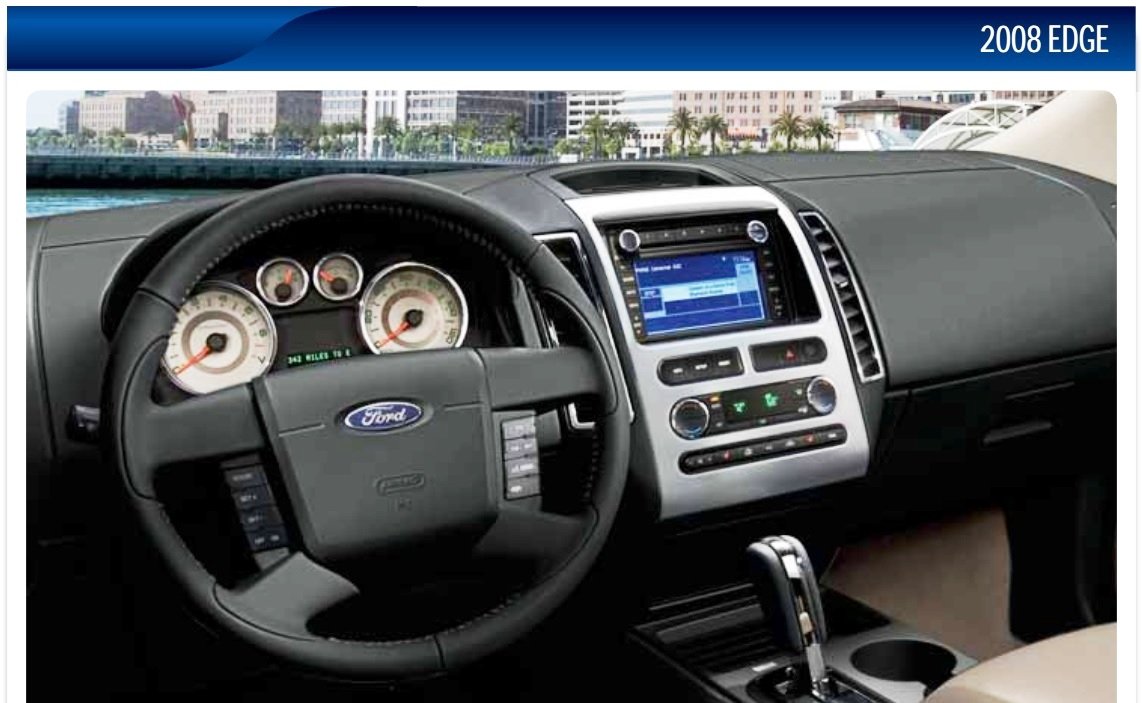
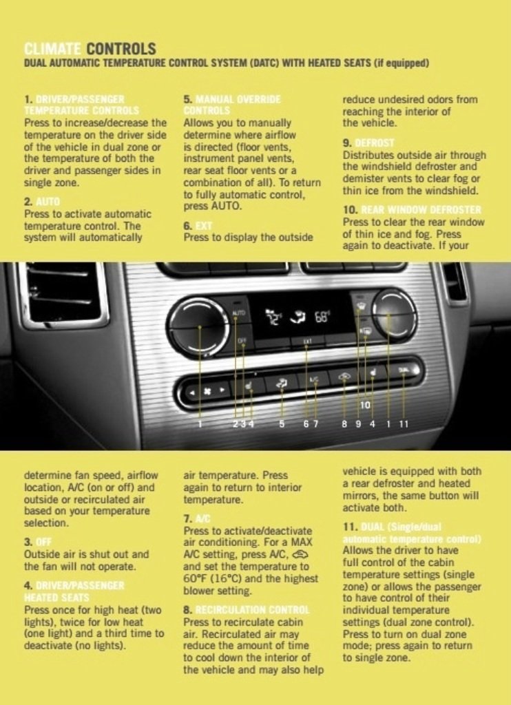
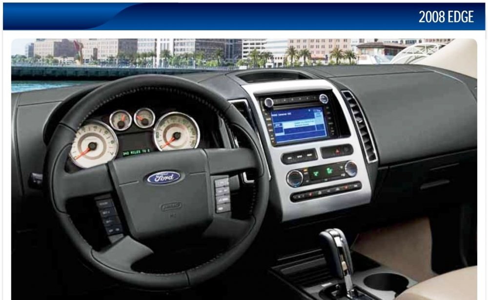
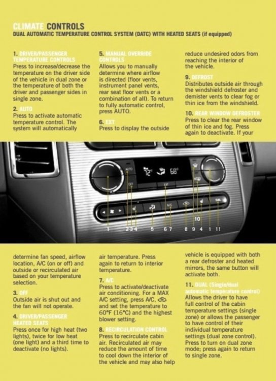
Or are you asking if any Forum member has converted their GEN 1 Edge from this... ...to this?... Good luck!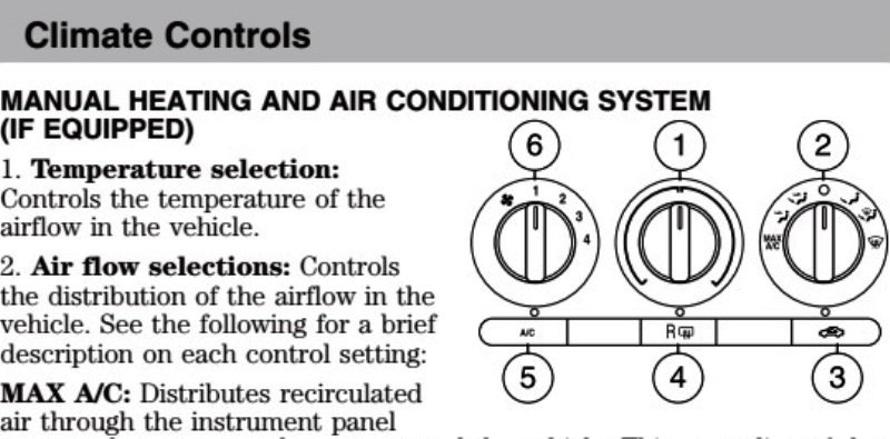
-
Below are PDF download links for documents relating to Ford Accessories PowerCode GEN 2 Remote Start/ Remote Keyless Entry/Security systems, circa 2007 model year. Ford Accessories - PowerCode GEN-2 2007 Model Year Installation & Technical Reference Manual.pdf Ford Accessories - PowerCode Gen-2 Installation Wiring Guide 2007 Edge-MKX - Version 1.pdf Ford Accessories - PowerCode Gen-2 Installation Wiring Guide 2007 Edge-MKX - Version 2.pdf Ford Accessories - PowerCode Programming Instructions.pdf Ford Accessories - PowerCode Remote Start System Diagnosis Guide - 2007 Edge.pdf Presuming we are not on one of those hidden-camera comedy shows, I will ask -- What the heck is a blow box? Good luck!
- 3 replies
-
- 1
-

-
- blow box
- remote start
- (and 3 more)
-
It was interesting to see, in the PDF download linked 2008 MY document below, that the PCM is the only listed module that employs Adaptive Learning... Module Configuration and Parameter Chart Module Name Reprogram/ Flash Capable Requires PMI Requires Adaptive Learning Requires Calibration Available Programmable Parameters ABS module Yes Yes No IVD initialization None APIM Yes Yes No No None ACM Yes Yes No No Phone module DSP module Yes Yes No No None DSM Yes Yes No No Easy entry/exit DCSM Yes Yes No No None Headlamp control module (HCM) Yes No No No None HVAC module Yes No No No None IC Yes Yes No No Belt-Minder® Overspeed warning Transit mode Liftgate/trunk module (LTM) Yes No No No None Occupant classification system module (OCSM) Yes No No OCS re-zero None PAM No Yes No No None PCM Yes Yes Yes No Axle ratio Tire size Speed control present RETM Yes Yes No No Language English/ Spanish/French SDARS RCM Yes Yes No No Driver seat Belt-Minder® Passenger seat Belt-Minder® SDARS module Yes Yes No No None SJB Yes Yes No Tire pressure monitoring system (TPMS) sensor training Autolocks Auto un-locking Daytime running lamps (DRL) Perimeter lighting mode Stoplamp outage enable/disable Steering angle sensor module (SASM) Yes No No No None 4X4 control module Yes No No No None Module Configuration - 2008 Edge Workshop Manual.pdf Good luck!
-
What symptom or Diagnostic Trouble Code (DTC) is your 2008 Edge exhibiting that causes you to want to force Powertrain Control Module (PCM) adaptive learning? Good luck!
-
SSM 50959 - 2019-2022 Edge/Nautilus, 2018-2022 Expedition/Navigator, 2020-2022 Explorer/Aviator - Family Entertainment System - Audio/Video Not Synced Using Vehicle Speakers Some 2019-2022 Edge/Nautilus, 2018-2022 Expedition/Navigator, 2020-2022 Explorer/Aviator vehicles equipped with a family entertainment system may experience the audio is not synchronized with the video display when using the vehicle speakers. To correct this condition, contact the VOXX Customer Service Department at 1-866-869-7888. For claiming, refer to the Warranty and Policy manual for Ford Licensed Accessories.
-
SSM 50960 - 2019-2022 Various Vehicles - 2.0L/2.3L EcoBoost - Light To Moderate Ticking Type Noise At Idle (600-700 RPM) Some 2019 MKC, 2019-2022 Edge/Nautilus/Escape/Ranger/Explorer, 2020-2022 Corsair, 2021-2022 Bronco Sport and 2022 Maverick vehicles equipped with 2.0L and 2.3L EcoBoost engines may exhibit a light to moderate ticking type noise at idle (600-700 RPM). The noise is usually more prominent in the area of the high-pressure fuel pump, located on the top of the engine just behind the number 4 ignition coil. This noise is not detrimental to engine function and has no effect on engine durability. This is an operating characteristic of these engines and no repairs should be attempted.
-
Heated/cooled seats not working. 2016 titanium
Haz replied to BlackTitanium's topic in Interior, A.C., Heat, Interior Trim
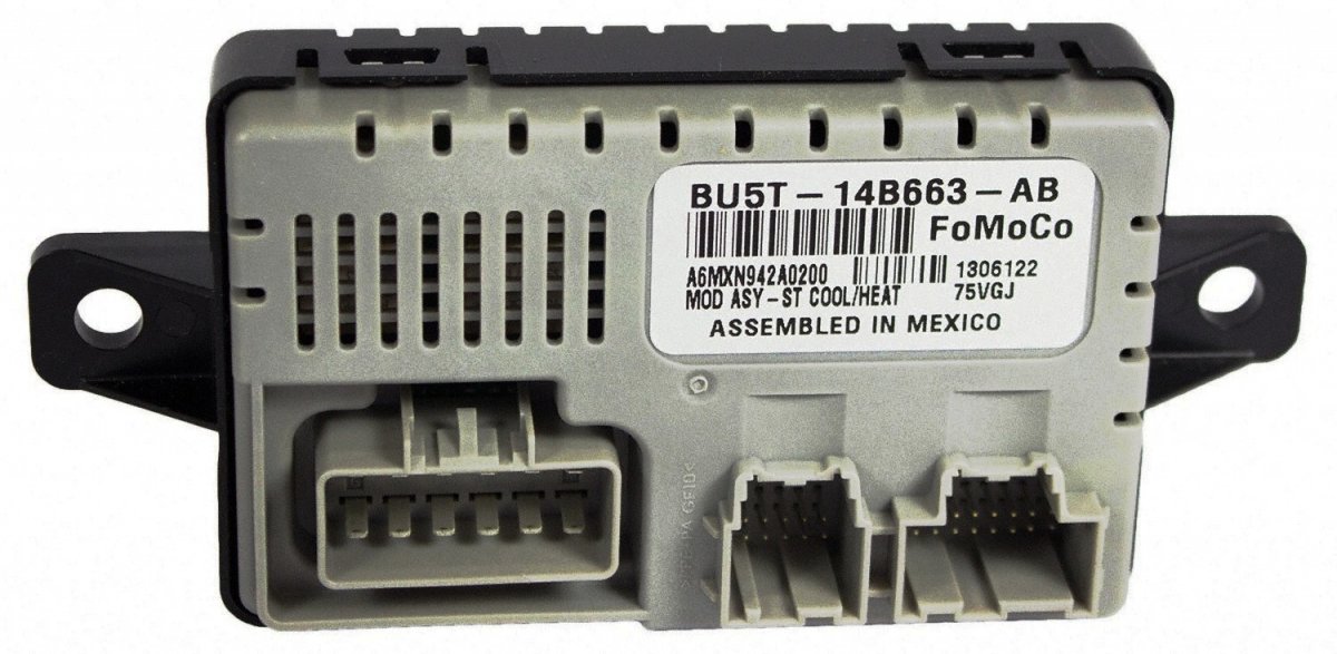
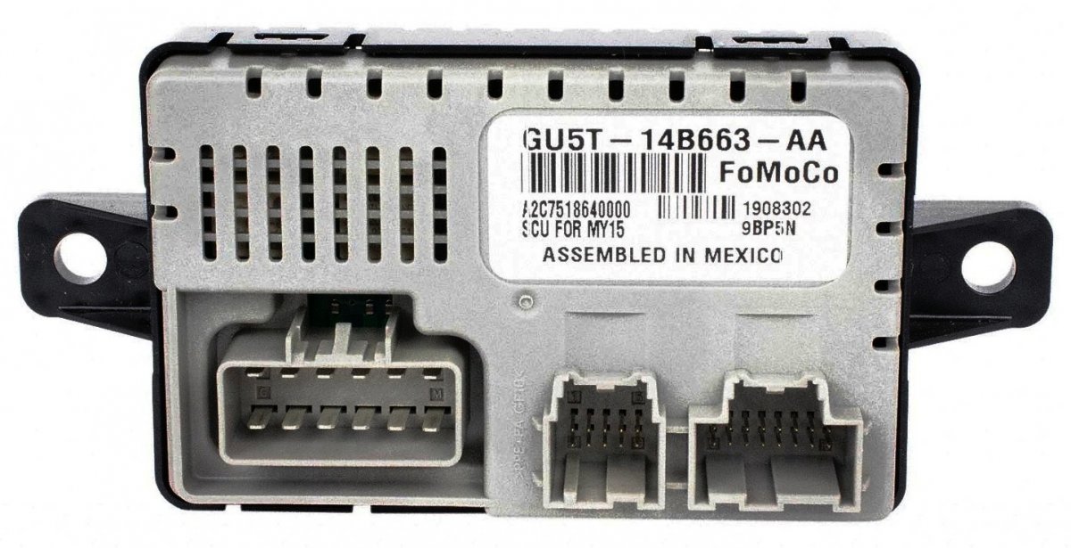
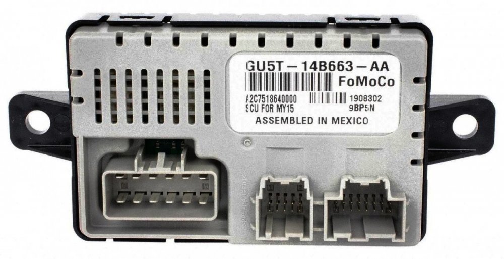
FordParts.com images for potential part number reference to Edge Build Date... Edge Usage 01-19-2015 - 07-20-2016, Edge 2015-, With Pass Heated And Cooled Seat, With Drivers Heated And Cooled Seat Edge Usage 07-20-2016 - 09-06-2018, Edge 2015-, With Pass Heated And Cooled Seat, With Drivers Heated And Cooled Seat Ford's FordParts.com site has a VIN-based search function that would be helpful toward identifying the appropriate part... As a double-check, you could take a camera-phone photo beneath the forward underside of the passenger seat to determine the current SCME's part number. Then, if the dealer hasn't obtained the replacement part yet, you could passive-agressively ask them what part number it was that they ordered. Good luck!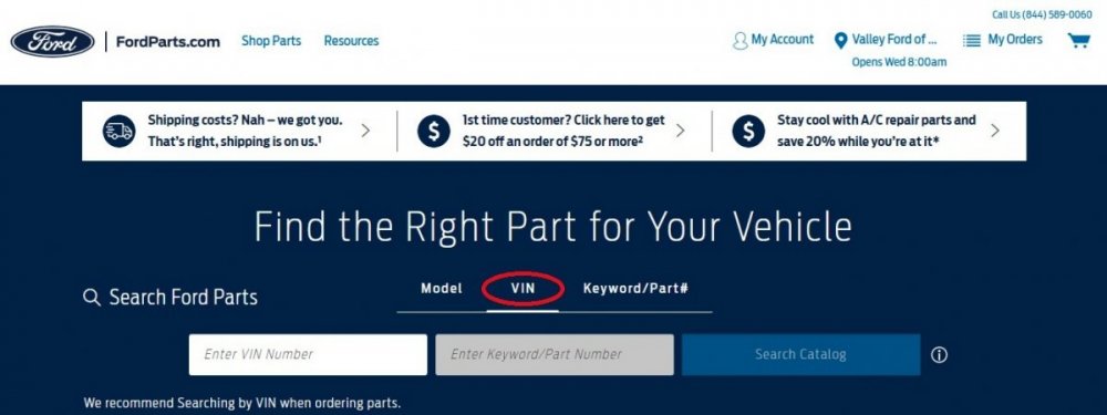

-
Heated/cooled seats not working. 2016 titanium
Haz replied to BlackTitanium's topic in Interior, A.C., Heat, Interior Trim
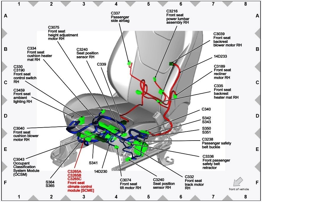
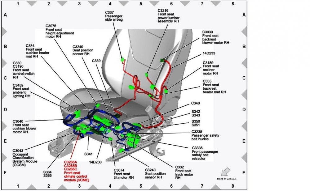
It sounds as though the dealer is not a Ford dealership, which I expect would perform diagnostic testing to ensure the part was actually faulty before they ordered its replacement. The following description of how the heated/cooled seats operate is from the 2016 Edge Workshop Manual. Where acronyms exist in the text, such as SCME, (which designates the Front Seat Climate Control Module which the dealer should be referring to), if you put your cursor over the acronym, its meaning should show up on your computer screen... Good luck! Climate Controlled Seat Operation The driver and passenger climate controlled seat buttons are selected from the FCIM and FDIM (touchscreen). The climate controlled seat system functions independently from the vehicle's climate control system. The seat cushion and backrest are each equipped with a blower motor assembly. As cabin air is drawn through each blower motor, a Thermo-Electric Device (TED) heats or cools the air, which is then directed into the foam pad where it is distributed along the surface of the cushion and backrest of the seat. Once the system is activated, the SCME uses a set of flexible algorithms to control the heating/cooling modes and the blower speed dependent on the commanded climate controlled seat settings. The SCME monitors seat cushion temperature while it supplies voltage and ground to both blower motors. The SCME also supplies a variable voltage signal to control the blower speed. Cabin air enters the blower through an integrated filter attached to the blower motor housing. Heated or cooled air exits the blower motor and flows through the foam pad. Climate Controlled Seat Heating Characteristics In heat mode, the blower motor can add up to 40–60° C (72–108° F) to the ambient inlet air temperature. The system control settings are indicated next to each climate controlled seat heat switch button on the touchscreen. The first setting is HIGH (3 indicators), the second setting is MED (2 indicators) and the third is LOW (1 indicator) then OFF (no indicators). When heating, the SCME varies the speed of the blower motors and the duty cycle of the integral Thermo-Electric Device (TED) in order to reach and maintain the desired temperature determined by the system control settings. Climate Controlled Seat Cooling Characteristics In cool mode, the blower motors can remove up to 8° C (14° F) from the ambient air temperature entering the system. The system control settings are based on the 3 indicators next to each climate controlled seat cool switch button on the touchscreen. The first setting is HIGH (3 indicators), the second setting is MED (2 indicators) and the third is LOW (1 indicator) then OFF (no indicators). When cooling, the SCME maintains a constant blower motor speed and a constant Thermo-Electric Device (TED) supply voltage (duty cycle is determined by the switch setting) in COOL mode. Climate Controlled Seat Recovery Mode NOTE: The presence of overtemperature faults (Diagnostic Trouble Codes (DTCs) B2729, B2730, B272A and B272B) can be induced by incorrectly operating the climate controlled seat system after an initial heat setting has been attained. If a heat setting is repeatedly turned off and on in an attempt to increase the seat temperature or repeatedly toggled between heat and cool modes, an overtemperature condition can result and the Diagnostic Trouble Codes (DTCs) may be set. If the temperature of one of the blower motors rises above 110° C (229.8° F) in the heat mode or 65° C (148.9° F) in the cool mode for more than 4 seconds, the SCME records an over-temperature DTC , removes voltage from the Thermo-Electric Devices (TEDs) (part of the blower motor assembly) and goes into recovery mode (blower only) for 30 seconds to cool down the blower motor. The same occurs if a temperature difference of 60° C (108° F) or greater is detected between the backrest and cushion blower motors on either front seat. The SCME continues to monitor the blower motors while in recovery mode. If the temperature of the Thermo-Electric Devices (TEDs) do not drop to 105° C (220.8° F) in the heat mode or 60° C (139.9° F) in the cool mode after 30 seconds, the system continues to cool the blower motors in recovery mode for up to 5 minutes. If the Thermo-Electric Devices (TEDs) cool down after 30 seconds, but before 5 minutes (checked at 4 second intervals), the system is operating normally. An over-temperature DTC is still recorded even if the system recovers and is operating normally. This is more likely to occur during extreme cabin temperatures with significant seat back sun load. If the system does not recover within 30 seconds in heat mode or within 5 minutes in cool mode, the SCME disables that seat (fault mode) and remains off until the ignition is cycled. Also, if the SCME detects a temperature differential fault twice during the same ignition cycle, the SCME disables the seat. When a fault causes a shutdown, the climate controlled seat indicators turn off and that seat is not operational until the next ignition cycle. Remote Start Climate Operation Different climate control modes/preferences can be selected when the vehicle is started using the remote start feature. This can be accessed through the message center. For additional information on how to set the remote start preferences, refer to the Owner's Literature. When the driver seat and/or passenger seat is set to AUTO mode, the driver/passenger heated/climate controlled seat activates in full heat mode when the outside temperature is less than 0° C (32° F) and full cool mode (climate controlled seats only) when outside temperature is greater than 27° C (80° F) any time the vehicle is started using the remote start feature. No heated/climate controlled seat adjustments are recognized during remote start operation. Once the ignition is cycled ON, the heated/climate controlled seat turns off. SCME Location Beneath Passenger Seat Front Seat Climate Control Module [SCME] Removal NOTE: This step is only necessary when installing a new component. NOTE: The PMI process must begin with the current SCME installed. If the current SCME does not respond to the diagnostic scan tool, the tool may prompt for As-Built Data as part of the repair. Using a diagnostic scan tool, begin the PMI process for the SCME following the on-screen instructions. NOTE: The SCME outboard mounting tab is located under the front seat front shield. Remove the screws and position the SCME aside. Remove the SCME . Release the locking wedges. Disconnect the electrical connectors. Installation To install, reverse the removal procedure. NOTE: This step is only necessary when installing a new component. Using a diagnostic scan tool, complete the PMI process for the SCME following the on-screen instructions Please notice that a new SCME cannot be installed and be expected to function without the original module's digital code being programmed into the new module after its installation. If the original code is not retrieved before the SCME is replaced, it is still possible to obtain the digital coding via so-called 'As Built Data' which is readily available through several sources. An appropriately equipped owner -- with computer awareness, a laptop computer, no-cost temporarily licensed Forscan software, and an OBDII adapter -- can cautiously accomplish this new-SCME programming task, referred to above as the PMI process. Listings on Ford's online parts site show the build date of the vehicle determines which SCME is needed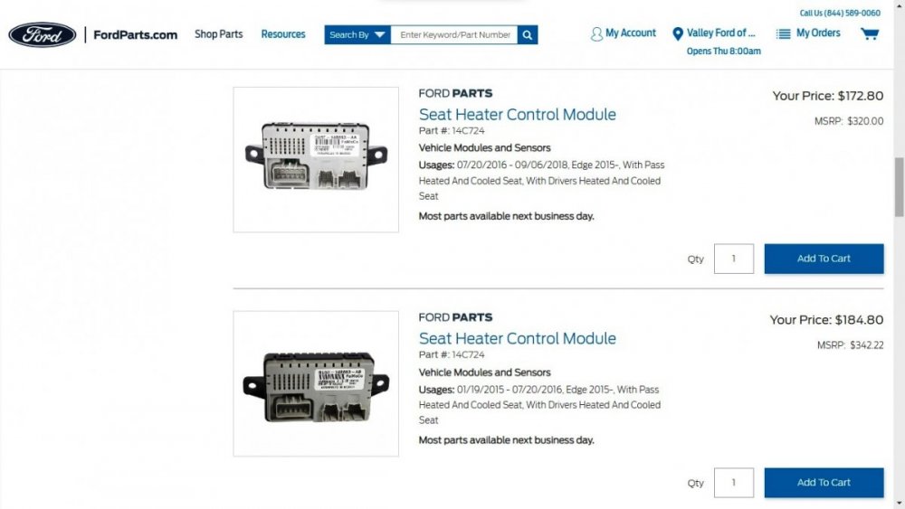
-
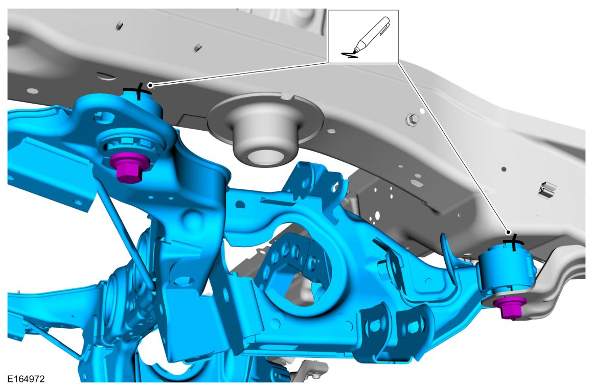
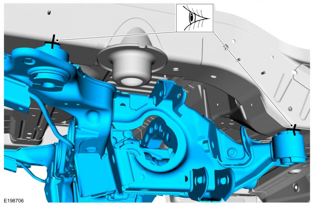
No experience, just information. I pulled a VIN-specific Historical Vehicle Bill of Materials (HVBoM) report on your Edge, which shows the components associated with the originally-installed Rear Subframe Assembly. The HVBoM report listed parts shown in the illustration you posted, and it also shows Bushing part numbers... Original Part Service Part Quantity Part Number Number Required Description E1GC5872AA E1GZ5872A 2 BUSHING F2GC5873AB F2GZ5872A 2 BUSHING In the HVBoM report, when an assembly component is not individually available for purchase, it will carry a 'PIA' designation, meaning it is 'provided in the assembly' only. In the case of the listing for Rear Subframe Assembly bushings, no PIA was shown. I searched the above bushing part numbers on Ford's FordParts.com site and came up with nothing for Edge, though the base part number 5872 does resolve to parts described as bushings for other models. If your Parts Counter contact didn't have these part numbers, see if they are helpful at the dealership. The 2017 Edge Workshop Manual includes the following images showing the Rear Subframe front & rear mounts where you believe the bushings reside... If the bushings are unavailable except in a new Rear Subframe, it would probably be a long shot, perhaps you could do a search of Salvage Yards for a low-miles wreck from which to scavenge the bushings -- if that's possible. And finally, I don't expect your skin will crawl any less, after you review the Workshop Manual procedures involved in Rear Subframe removal and installation, included below as a PDF download link... Rear Subframe - AWD - Removal and Installation - 2017 Edge Workshop Manual.pdf Good luck!

-
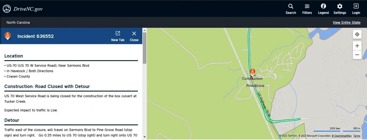
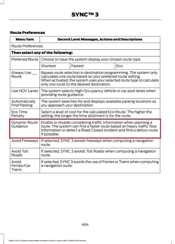
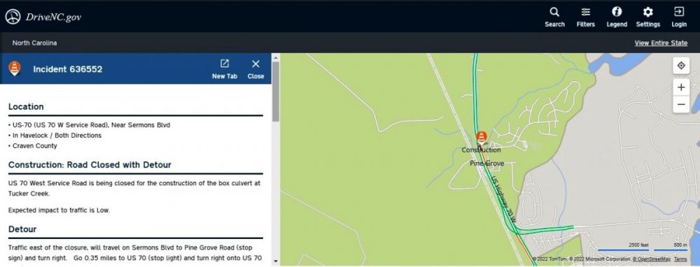
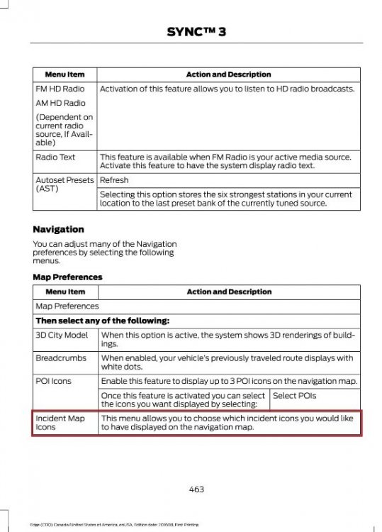
So, in both cases -- presuming you have selected Incident Icons to appear on your Map -- there are no icons showing an incident that may be affecting the Dynamic Routing outcomes, perhaps explaining the purple-colored US 70/New Bern map segment? Good luck!
-
Forgive me for my reverse pun at the opening, which I did not clearly announce. On the road segment you characterized as a Construction Zone, what Incident Icons are showing as faulty or potentially triggering the re-route? Asked another way, while they are not the same place, what road segment color and/or Incident Icons show on the US 70 stretch in Havelock that NC DOT reports as being a closure with detour?... Good luck!
-
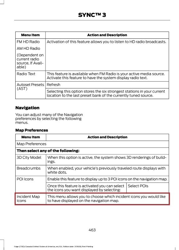
Your Edge's navigation issue is not-at-all Sirius. The Sync 3 Navigation route-making behavior is likely the result of the Dynamic Route Planning Route Preference being set as 'Enabled', per this description in the 2017 Edge Owner's Manual... Disabling Dynamic Route Guidance should cause subsequent routes planned according to your Edge's other Navigation preferences, without any pre-consideration given to the Sirius Traffic & Incident data. The Sirius-informed Construction Zone color-change to purple may denote lane restrictions in both directions of that stretch of road. You can check this by changing Navigation Map Preferences and selecting Incident Map Icons to stay informed about what's happening on your route, per the 2017 Edge Owner's Manual... And, in the word's of actor Michael Conrad as Sgt. Phil Esterhaus in Hill Street Blues, "Let's be careful out there." Good luck!

-
Climate Fan repeatedly turns all the way up!
Haz replied to ab50228's topic in Interior, A.C., Heat, Interior Trim