Haz
-
Posts
1,460 -
Joined
-
Last visited
-
Days Won
392
Content Type
Profiles
Forums
Gallery
Everything posted by Haz
-
Clips holding grille to bumper - how to undo them?
Haz replied to gibbey531's topic in Accessories & Modifications
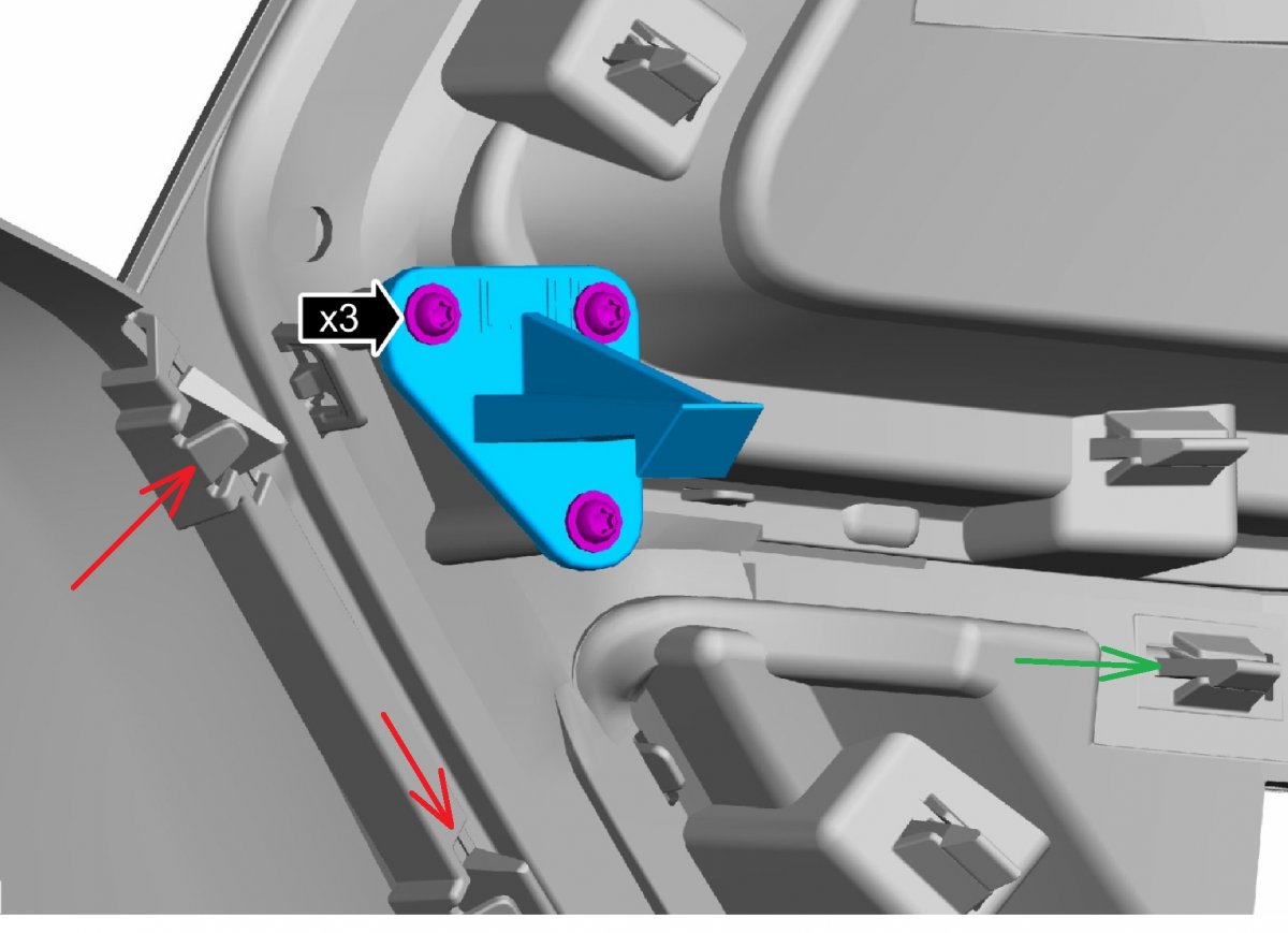
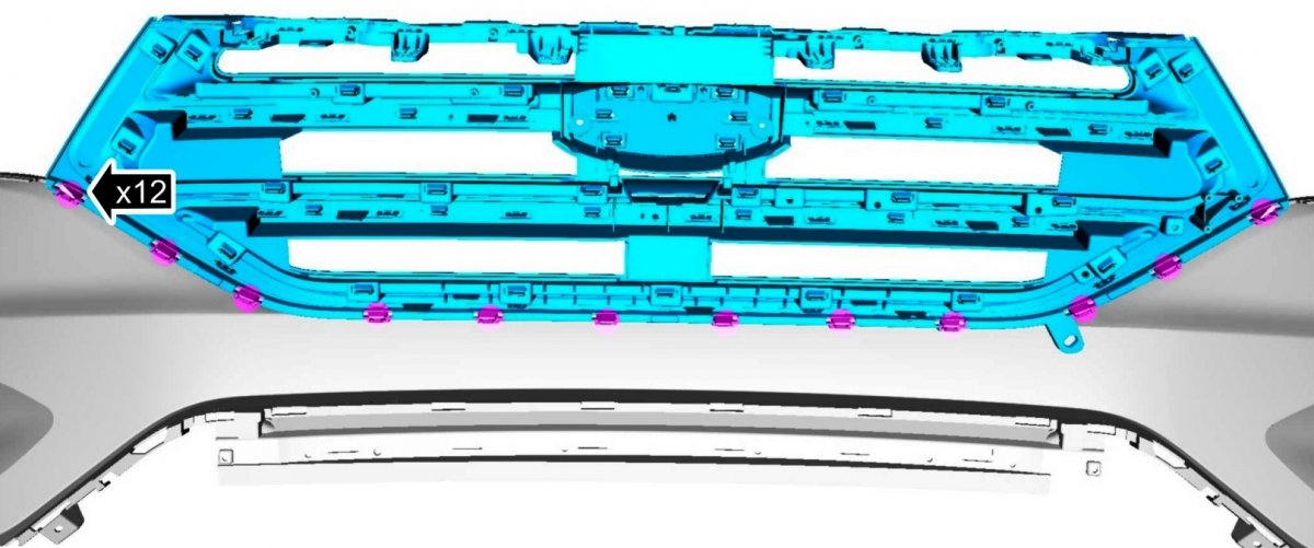
Welcome to the Forum, gibbey531! The 2017 Edge Workshop Manual description regarding separating the grille from the bumper cover lists no special-tool need and advises to "Release the tabs and remove the upper radiator grille"... In this high-resolution Workshop Manual illustration, it appears that the grille is retained by its twelve J-hooked rectangular posts (red arrows) which insert through slots in the bumper cover and latch over the bumper cover material, comparable in design to the green-arrowed post retaining an applique on the grille's front face... Hopefully, once you remove the bumper cover assembly, the grille removal will be easier that you expect, since no special tool or replacement clips are specified as necessary in the procedure. Document download links> Front Bumper Cover - Removal and Installation - 2017 Edge Workshop Manual.pdf Front Bumper Cover - Component Removal and Installation - 2017 Edge Workshop Manual.pdf Good luck!

- 1 reply
-
- 2
-

-

-
Best way to get scratch out of console?
Haz replied to gibbey531's topic in Appearance - Detailing, Wash & Wax
As long as the visual defect is from the disturbance of the stipple finish and not the result of color-change within the furrow of the scratch... I'd be tempted to try overlaying the entire shelf-face with touchscreen protective film, which is fairly rigid, available in non-glare finish, would resist future scratches, and should be easily removable if it didn't work out. Hopefully, the continuity of the protective film's surface would eliminate the visibility of the scratches. Web-searching touchscreen protective film yields a variety of sources of tablet & laptop sized self-adhering sheets, which could be trimmed to size using a satisfactory self-created template. Good luck! -
Passenger seat, no heat or a/c
Haz replied to enigma-2's topic in Interior, A.C., Heat, Interior Trim
From the Ford Media Center, January 26, 2023... FORD ANNOUNCES NATIONWIDE EXPANSION OF COMPLIMENTARY PICKUP & DELIVERY, MOBILE SERVICE FOR ALL FORD CUSTOMERS Ford is expanding and enhancing its remote experiences offerings to make complimentary Pickup & Delivery and Mobile Service appointments available to all Ford Service customers The nationwide acceleration is part of Ford’s commitment to improve the ownership experience by providing convenient, seamless options for vehicle service, from simple oil changes to recall repairs Increasing access to remote experiences is fueled by positive sentiment, brand loyalty and customer demand for more personalized service options DEARBORN, Mich., Jan. 26, 2023 – Ford customers nationwide now can enjoy complimentary Pickup & Delivery as well as expanded mobile services from participating dealers as part of the company’s increased commitment to enhancing the ownership experience. According to the J.D. Power 2022 U.S. Customer Service Index (CSI) Study, data shows that customers who utilize remote experiences for vehicle repair are more likely to recommend their brand to a friend or family member. “Customers who’ve experienced Pickup & Delivery and Mobile Service love the convenience and flexibility,” said Todd Rabourn, North America Regional CX Director. “This program increases the access customers have to remote service options, so whether you’re due for an oil change or need to resolve a recall, it’s easier to have your vehicle serviced with less disruption to your life, and the activities and people you care about.” The expanded program provides dealers with additional support to offer the complimentary remote services. “We’ve been working with multiple teams at Ford to offer our customers more ways to personalize vehicle service,” said Tim Hovik, National Dealer Council Chairperson. “By expanding the remote experiences offerings, we can accelerate our ability to be there for customers whenever and wherever they need us.” With Pickup & Delivery, the customer’s preferred Ford dealer will come to their home or place of business, pick up their vehicle and return it when the repair has been completed. This adds convenience and choice to the service experience while minimizing downtime. For light repairs and routine maintenance, a Mobile Service van can be dispatched with a trained technician to perform service at an eligible location of the customer’s choice. Participating dealers have the ability to set their own service and mileage limits for each type of remote experience. Rabourn says that Ford customers appreciate the time savings and consistently rate their satisfaction and willingness to recommend the Ford brand higher as a result of offering remote experiences. The remote experiences program is voluntary for dealers and all Ford Service customers can take advantage of complimentary Pickup & Delivery and Mobile Service appointments from participating dealers including retail, fleet, commercial and government customers. -
From the 2013 Edge Workshop Manual... Specifications Material Item Specification Fill Capacity Motorcraft® A/C System Flushing Solvent YN-23 — — Motorcraft® PAG Refrigerant Compressor Oil YN-12-D WSH-M1C231-B 118 ml (4 fl oz) Motorcraft® R-134a Refrigerant YN-19 (US); CYN-19-R (Canada); MYN-19 (Mexico) WSH-M17B19-A 0.54 kg (19 oz) (1.19 lb) Stay-Brite® R-134a Leak Detection Dye 164-R6060 (Rotunda) — — Climate Control System WARNING: Take the following precautions when repairing an air conditioning system containing R-134a: Always wear safety goggles. Avoid contact with liquid refrigerant R-134a. R-134a vaporizes at approximately -25°C (-13°F) under atmospheric pressure and will freeze skin tissue. Never allow refrigerant R-134a gas to escape in quantity in an occupied space. It will displace the oxygen needed to support life. Never use a torch in an atmosphere containing R-134a gas. R-134a is non-toxic at all normal conditions, but it decomposes when exposed to high temperatures such as a torch flame. During decomposition it releases irritating and toxic gasses (as described in the Material Safety Data Sheet from the manufacturer). Decomposition products are hydrofluoric acid, carbon dioxide and water. Failure to follow these instructions may result in serious personal injury. NOTICE: To avoid damaging the vehicle or Air Conditioning (A/C) components, observe the following precautions. Identify and analyze the A/C refrigerant of all vehicles prior to refrigerant charging. Failure to do so can contaminate the shop bulk refrigerant and other vehicles. Do not add R-12 refrigerant to an A/C system that uses R-134a refrigerant. These 2 types of refrigerant must never be mixed. Doing so can damage the A/C system. To prevent refrigerant slugging from damaging the A/C compressor, charge the A/C system with R-134a refrigerant gas while the engine is running only at the low-pressure side. Use only R-134a refrigerant. Due to environmental concerns, when the A/C system is drained, the refrigerant must be collected using refrigerant recovery/recycling equipment. Federal, State/Provincial and/or local laws REQUIRE that R-134a be recovered into appropriate recovery equipment and the process be conducted by qualified technicians who have been certified by an approved organization, such as Automotive Service Excellence (ASE) or Mobile Air Conditioning Society (MACS) . Use of a recovery machine dedicated to R-134a reduces the possibility of oil and refrigerant incompatibility concerns. Refer to the instructions provided by the equipment manufacturer when removing refrigerant from or charging the A/C system. R-134a refrigerant must not be mixed with air for leak testing or used with air for any other purpose above atmospheric pressure. R-134a is combustible when mixed with high concentrations of air and higher pressures. A number of manufacturers are producing refrigerant products that are described as direct substitutes for refrigerant R-134a. The use of any unauthorized substitute refrigerant can severely damage the A/C components. If repair is required, use only new or recycled refrigerant R-134a. NOTICE: To avoid contamination of the Air Conditioning (A/C) system, observe the following precautions. Never open or loosen a connection before recovering the refrigerant. When loosening a connection, if any residual pressure is evident, allow it to leak out before opening the fitting. Evacuate a system that has been opened to install a new component or one that has discharged through leakage before charging. Seal open fittings with a cap or plug immediately after disconnecting a component from the system. Clean the outside of the fittings thoroughly before disconnecting a component from the system. Do not remove the sealing caps from a new component until ready to install. Refrigerant oil absorbs moisture from the atmosphere if left uncapped. Do not open an oil container until ready to use and install the cap immediately after using. Store the oil in a clean, moisture-free container. Install a new O-ring seal before connecting an open fitting. Coat the fitting and O-ring seal with PAG oil before connecting. When installing a refrigerant line, avoid sharp bends. Position the line away from the exhaust or any sharp edges that can chafe the line. Tighten threaded fittings only to specifications. The steel and aluminum fittings used in the refrigerant system will not tolerate overtightening. When disconnecting a fitting, use a wrench on both halves of the fitting to prevent twisting of the refrigerant lines or tubes. Do not open a refrigerant system or uncap a new component unless it is as close as possible to room temperature. This prevents condensation from forming inside a component that is cooler than the surrounding air. Fluorescent Dye Detection NOTE: Ford Motor Company vehicles are produced with R-134a fluorescent dye installed in the refrigerant system from the factory. The location of leaks can be pinpointed by the bright yellow-green glow of the fluorescent dye under a UV lamp. Since more than one leak can exist, make sure to inspect each component, line and fitting in the refrigerant system for a leak. Check for leaks using a Rotunda-approved UV lamp. Inspect all components, lines and fittings of the refrigerant system. If a leak is found, recover the refrigerant. For additional information, refer to Air Conditioning (A/C) System Recovery, Evacuation and Charging in this section. Repair the refrigerant system leak(s). Evacuate and charge the refrigerant system. For additional information, refer to Air Conditioning (A/C) System Recovery, Evacuation and Charging in this section. After the leak(s) is/are repaired, remove any traces of fluorescent dye with a general purpose oil solvent. Verify the repair by running the vehicle for a short period of time and rechecking the area of the leak with a Rotunda-approved UV lamp. NOTE: Fluorescent refrigerant system dye is added to the refrigerant system at the factory to assist in refrigerant system leak diagnosis using a Rotunda-approved ultraviolet blacklight. It is not necessary to add additional dye to the refrigerant system before diagnosing leaks, even if a significant amount of refrigerant has been removed from the system. Additional refrigerant system dye should only be added if more than 50% of the refrigerant system lubricant capacity has been lost due to a fitting separation, hose rupture or other damage. Good luck!
-
Document download links> 2024 Lincoln Nautilus Order Guide.pdf 2024 Lincoln Nautilus Technical Specifications.pdf Link to Lincoln Media Center press release with photos.
-
It might be useful to see if Forscan shows a Select-Shift enable/disable function for your Edge, versus needing to manually program the PCM As-Built entries -- perhaps after comparing your non-Select-Shift Edge's PCM As-Built data to a comparably equipped Select-Shift Edge's PCM As-built data. Wiring diagrams, connector details & locations, a few component removal and installation procedures for you to contemplate... Document download links> Clockspring - 8F35 Trans With Adaptive Steering - Connector C218E Details - 2022 Edge.pdf Clockspring - 8F35 Trans Without Adaptive Steering - Connector C218A Details - 2022 Edge.pdf Clockspring - 8F35 Trans Without Adaptive Steering - Connector C218A Location - 2022 Edge.pdf Clockspring - 8F35 Trans Without Adaptive Steering - Connector C218B Details - 2022 Edge.pdf Clockspring - 8F35 Trans Without Adaptive Steering - Connector C218G Details - 2022 Edge.pdf Clockspring - Removal and Installation - 2022 Edge Workshop Manual.pdf Clockspring + Other Steering Wheel Connectors Locations - 2022 Edge.pdf Upshift Paddle Switch - Connector C2428 Details - 2022 Edge.pdf Downshift Paddle Switch - Connector C2429 Details - 2022 Edge.pdf Paddle Shift - With Adaptive Steering - Wiring Diagram - 2022 Edge Workshop Manual.pdf Paddle Shift - Without Adaptive Steering - Wiring Diagram - 2022 Edge Workshop Manual.pdf Powertrain Control Module (PCM) - Connector 1381B Details - 2022 Edge.pdf Powertrain Control Module (PCM) - Connector 1381B Location, Rear RH Side Engine Compartment - 2022 Edge.pdf Powertrain Control Module (PCM) - Removal and Installation - 2022 Edge Workshop Manual.pdf Powertrain Control Module (PCM) to Internal Transmission Controls - Wiring Diagram 1 - 2022 Edge.pdf Powertrain Control Module (PCM) to Internal Transmission Controls - Wiring Diagram 2 - 2022 Edge.pdf Powertrain Control Module (PCM) to Internal Transmission Controls - Wiring Diagram 3 - 2022 Edge.pdf Powertrain Control Module (PCM) to Steering Wheel Transmission Controls - Inline Connector C238 Details - 2022 Edge.pdf Powertrain Control Module (PCM) to Steering Wheel Transmission Controls - Inline Connector C238 Location - 2022 Edge.pdf Powertrain Control Module (PCM) to Steering Wheel Transmission Controls - Wiring Diagram - 2022 Edge.pdf STEERING COLUMN CONTROL MODULE (SCCM) - 8F35 Trans Without Adaptive Steering - Connector C226 Details - 2022 Edge.pdf STEERING COLUMN CONTROL MODULE (SCCM) - 8F35 Trans Without Adaptive Steering - Connector C226 Location - 2022 Edge.pdf Steering Column Control Module (SCCM) - Removal and Installation - 2022 Edge Workshop Manual.pdf Good luck!
-
Can nav be added to a 2022 Edge with Sync 4A?
Haz replied to JohnCT's topic in Audio, Backup, Navigation & SYNC
Ford released the following Special Service Message to dealerships on August 26, 2022... SSM 51055 Adding/Removing Features Using Programmable Parameters Due To Vehicle Modifications Ford and Lincoln vehicle owners may request modifications to their vehicle such as enabling daytime running lamps (DRL), adding navigation, changing tire/axle sizes, and/or adding trailer brake control modules. A list of programmable parameters that are available for alteration is shown in Workshop Manual (WSM), Section 418-01A > Module Configuration. Parameters available for alteration will vary by model and model year. If the desired parameter is not listed in the right column of the Module Configuration and Parameter Chart, alteration of that parameter is not supported by Ford Motor Company. A list of supported parts that can be added to the vehicle is available at accessories.ford.com. Adding/removing accessories and/or programming vehicle features is not warrantable. 2014 was the final Model Year for Navigation to be shown as an approved dealer-programmable APIM/SYNC Module parameter for Edge/MKX vehicles. At the dealership level, a vehicle's SYNC Service Report in Ford's OASIS database includes the serial number of the originally installed APIM/SYNC module, as well as a last-recorded software list which shows if Navigation was previously present. With Ford's software servers releasing OTA updates by vehicle VIN, I wonder how SYNC and map updates would occur, though the Internet-at-large is a possible source. To update the old saying: Where there's a will -- and enough money -- there's a way. And it will likely void some portion of Ford's warranty. Good luck! -
From the Ford Powertrain Control/Emissions Diagnosis (PC/ED) Manual for 2008 Gasoline Engines... P0340 - Camshaft Position Sensor A Circuit (Bank 1 or single sensor) Description: The test fails when the powertrain control module (PCM) can no longer detect the signal from the camshaft position (CMP) sensor on bank 1. Possible Causes: CMP circuit open CMP circuit short to GND CMP circuit short to voltage SIG RTN open (VR sensor) CMP GND open (Hall-effect sensor) CMP circuit short to CMP2 circuit (if equipped) CMP incorrectly installed (Hall-effect sensor) Damaged CMP sensor shielding Damaged CMP sensor Damaged PCM Diagnostic Aids: Harness routing, harness alterations, incorrect shielding, or electrical interference from other systems may have an intermittent impact on the CMP signal. Application Key On Engine Off Key On Engine Running Continuous Memory All GO to Pinpoint Test DR. P0344 - Camshaft Position Sensor A Circuit Intermittent (Bank 1 or single sensor) Description: The test fails when the powertrain control module (PCM) detects an intermittent signal from the camshaft position (CMP) sensor. Possible Causes: Intermittent open circuit Intermittent short circuit Damaged sensor shielding Damaged sensor Diagnostic Aids: Harness routing, harness alterations, incorrect shielding, or electrical interference from other systems may have an intermittent impact on the CMP signal. Application Key On Engine Off Key On Engine Running Continuous Memory All — — GO to Pinpoint Test DR. Pinpoint Test DR: Camshaft Position (CMP) Sensor This pinpoint test is intended to diagnose the following: camshaft position (CMP) sensor (6B288) harness circuits: CMP, CMP2, SIGRTN, VBPWR, VRSRTN, and VRSRTN2 powertrain control module (PCM) (12A650) DR1 CHECK FOR DIAGNOSTIC TROUBLE CODES (DTCS) Are DTCs P0340, P0344, P0345, or P0349 present? Yes For DTCs P0340, P0344, P0345 or P0349, GO to DR2. No For all others, GO to Section 4, Diagnostic Trouble Code (DTC) Charts and Descriptions. DR2 CONTINUOUS MEMORY DTCS P0340, P0344, P0345 AND P0349: CHECK IF THE ENGINE STARTS Attempt to start the engine. Does the engine start? Yes GO to DR3. No For symptoms without DTCs, RETURN to Section 3, Symptom Charts for further direction. For vehicles with DTCs and a no crank symptom, GO to DR19. For all others, GO to DR3. DR3 CLEAR AND ATTEMPT TO RETRIEVE THE DTC Note: If DTCs P0340, P0344, P0345, or P0349 are present, ignition, alternator noise, RFI and CKP concerns should be considered. Note: For vehicles with variable camshaft timing (VCT), concerns with the engine oil level, oil filter, oil contamination, or the VCT system may cause camshaft positioning errors. Ignition ON, engine OFF. Clear the PCM DTCs. Ignition ON, engine running. Increase engine speed to greater than 1,500 RPM for 10 seconds. Repeat this 3 times. Carry out the PCM self-test. Are DTCs P0340, P0344, P0345 or P0349 present? Yes GO to DR4. No GO to Pinpoint Test Z. DR4 CHECK THE GENERATOR FOR EXCESSIVE ELECTRICAL NOISE Note: If the generator/regulator is electrically noisy, the noise decreases when the B+ connector is disconnected. PCM connector connected. CMP Sensor connector connected. Ignition ON, engine running. Monitor the generator for an audible electric noise. Ignition OFF. Generator/regulator B+ connector disconnected. Ignition ON, engine running. With the engine running, determine if the generator is still noisy. Does the noise remain constant when the B+ connector is disconnected? Yes For continuous memory DTCs P0340 or P0344, GO to DR5. For continuous memory DTCs P0345 or P0349, GO to DR13. No REFER to the Workshop Manual Section 414-00, Charging System to diagnose the generator is noisy symptom. DR5 DETERMINE THE CMP SENSOR PHYSICAL TYPE Ignition OFF. Is the CMP sensor a synchronizer (gear driven) type? Yes GO to DR6. No GO to DR7. DR6 VERIFY THE CORRECT INSTALLATION OF THE CMP SENSOR Note: A CMP sensor identifies the cylinder 1 power stroke. A sensor that is improperly installed/indexed can identify the wrong cylinder as 1, produce a tip-in hesitation and generate DTC P0340. Is the CMP sensor installed correctly? Yes GO to DR7. No INSTALL the CMP sensor correctly. REFER to the Workshop Manual Section 303-14, Electronic Engine Controls for the Camshaft Synchronizer removal and installation procedures. CLEAR the DTCs. REPEAT the self-test. DR7 DETERMINE THE CMP SENSOR ELECTRONIC TYPE Note: The variable reluctance (VR) sensors have 2-wire connectors, Hall-effect sensors have 3-wire connectors. Is the CMP sensor a VR type? Yes GO to DR8. No The CMP sensor is a Hall-effect type. GO to DR19. DR8 CONTINUOUS MEMORY DTCS P0340 AND P0344: CHECK THE CMP SENSOR RESISTANCE Note: For vehicles with 2-pin CMP sensors, measure the circuits listed in the table that apply to 2-pin sensors. Ignition OFF. CMP Sensor connector disconnected. Measure the resistance between: ( + ) CMP Sensor Connector, Component Side ( - ) CMP Sensor Connector, Component Side CMP SIGRTN CMP VRSRTN Vehicle Minimum Resistance (ohms) Maximum Resistance (ohms) Edge, MKX 586 2,033 Is the resistance within specification? Yes GO to DR9. No INSTALL a new CMP sensor. REFER to the Workshop Manual Section 303-14, Electronic Engine Controls. CLEAR the DTCs. REPEAT the self-test. DR9 CHECK THE CMP CIRCUIT FOR A SHORT TO VOLTAGE IN THE HARNESS PCM connector disconnected. Ignition ON, engine OFF. Measure the voltage between: ( + ) CMP Sensor Connector, Harness Side ( - ) Vehicle Battery CMP Negative terminal Is the voltage less than 1 V? Yes GO to DR10. No REPAIR the short circuit. CLEAR the DTCs. REPEAT the self-test. DR10 CHECK THE CMP AND SIGRTN OR VRSRTN CIRCUITS FOR AN OPEN IN THE HARNESS Note: For vehicles with 2-pin CMP sensors, measure the circuits listed in the table that apply to 2-pin sensors. Ignition OFF. Measure the resistance between: ( + ) PCM Connector, Harness Side ( - ) CMP Sensor Connector, Harness Side CMP CMP SIGRTN SIGRTN VRSRTN VRSRTN Are the resistances less than 5 ohms? Yes GO to DR11. No REPAIR the open circuit. CLEAR the DTCs. REPEAT the self-test. DR11 CHECK FOR A SHORT IN THE HARNESS BETWEEN THE PCM AND THE CMP SENSOR Note: For vehicles with 2-pin CMP sensors, measure the circuits listed in the table that apply to 2-pin sensors. Measure the resistance between: ( + ) CMP Sensor Connector, Harness Side ( - ) CMP Sensor Connector, Harness Side CMP SIGRTN CMP VRSRTN Measure the resistance between: ( + ) CMP Sensor Connector, Harness Side ( - ) Vehicle Battery CMP Negative terminal SIGRTN Negative terminal VRSRTN Negative terminal Are the resistances greater than 10K ohms? Yes GO to DR12. No REPAIR the short circuit. CLEAR the DTCs. REPEAT the self-test. DR12 CHECK THE CMP SENSOR OUTPUT Note: For vehicles with 2-pin CMP sensors, measure the circuits listed in the table that apply to 2-pin sensors. For vehicles with 3-pin CMP sensors, measure the circuits listed in the table that apply to 3-pin sensors. Refer to connector end views at beginning of pinpoint test. Ignition OFF. Generator/regulator B+ connector connected. CMP Sensor connector disconnected. Ignition ON, engine running. Digital multimeter (DMM) on low voltage AC scale. Measure the voltage between: ( + ) CMP Sensor Connector, Component Side ( - ) CMP Sensor Connector, Component Side CMP SIGRTN CMP VRSRTN Run the engine at approximately 2,500 RPM. Is the voltage greater than 0.25 V? Yes GO to DR26. No INSTALL a new CMP sensor. REFER to the Workshop Manual Section 303-14, Electronic Engine Controls. CLEAR the DTCs. REPEAT the self-test. DR13 CONTINUOUS MEMORY DTCS P0345 AND P0349: CHECK THE CMP2 SENSOR RESISTANCE Note: For vehicles with 2-pin CMP sensors, measure the circuits listed in the table that apply to 2-pin sensors. Ignition OFF. CMP2 Sensor connector disconnected. Measure the resistance between: ( + ) CMP2 Sensor Connector, Component Side ( - ) CMP2 Sensor Connector, Component Side CMP2 SIGRTN CMP2 VRSRTN CMP2 VRSRTN2 Vehicle Minimum Resistance (ohms) Maximum Resistance (ohms) Edge, MKX 586 2,033 Is the resistance value(s) within specifications? Yes GO to DR14. No INSTALL a new CMP2 sensor. REFER to the Workshop Manual Section 303-14, Electronic Engine Controls. CLEAR the DTCs. REPEAT the self-test. DR14 CHECK THE CMP2 CIRCUIT FOR A SHORT TO VOLTAGE IN THE HARNESS PCM connector disconnected. Ignition ON, engine OFF. Measure the voltage between: ( + ) CMP2 Sensor Connector, Harness Side ( - ) Vehicle Battery CMP2 Negative terminal Is the voltage less than 1 V? Yes GO to DR15. No REPAIR the short circuit. CLEAR the DTCs. REPEAT the self-test. DR15 CHECK THE CMP2 AND SIGRTN, VRSRTN, OR VRSRTN2 CIRCUITS FOR AN OPEN IN THE HARNESS Note: For vehicles with 2-pin CMP sensors, measure the circuits listed in the table that apply to 2-pin sensors. Ignition OFF. Measure the resistance between: ( + ) PCM Connector, Harness Side ( - ) CMP2 Sensor Connector, Harness Side CMP2 CMP2 SIGRTN SIGRTN VRSRTN VRSRTN VRSRTN2 VRSRTN2 Are the resistances less than 5 ohms? Yes GO to DR16. No REPAIR the open circuit. CLEAR the DTCs. REPEAT the self-test. DR16 CHECK FOR A SHORT IN THE HARNESS BETWEEN THE PCM AND THE CMP2 SENSOR Note: For vehicles with 2-pin CMP sensors, measure the circuits listed in the table that apply to 2-pin sensors. Measure the resistance between: ( + ) CMP2 Sensor Connector, Harness Side ( - ) CMP2 Sensor Connector, Harness Side CMP2 SIGRTN CMP2 VRSRTN CMP2 VRSRTN2 Measure the resistance between: ( + ) CMP2 Sensor Connector, Harness Side ( - ) Vehicle Battery CMP2 Negative terminal SIGRTN Negative terminal VRSRTN Negative terminal VRSRTN2 Negative terminal Are the resistances greater than 10K ohms? Yes GO to DR17. No REPAIR the short circuit. CLEAR the DTCs. REPEAT the self-test. DR17 CHECK FOR A SHORT BETWEEN THE CMP AND THE CMP2 CIRCUITS CMP Sensor connector disconnected. CMP2 Sensor connector disconnected. Measure the resistance between: ( + ) PCM Connector, Harness Side ( - ) PCM Connector, Harness Side CMP CMP2 Is the resistance greater than 10K ohms? Yes GO to DR18. No REPAIR the short circuit. CLEAR the DTCs. REPEAT the self-test. DR18 CHECK THE CMP2 SENSOR OUTPUT Note: For vehicles with 2-pin CMP sensors, measure the circuits listed in the table that apply to 2-pin sensors. Ignition OFF. Generator/regulator B+ connector connected. CMP2 Sensor connector disconnected. Ignition ON, engine running. DMM on low voltage AC scale. Measure the voltage between: ( + ) CMP2 Sensor Connector, Component Side ( - ) CMP2 Sensor Connector, Component Side CMP2 SIGRTN CMP2 VRSRTN CMP2 VRSRTN2 Run the engine at approximately 2,500 RPM. Is the voltage greater than 0.25 V? Yes GO to DR26. No INSTALL a new CMP2 sensor. REFER to the Workshop Manual Section 303-14, Electronic Engine Controls. CLEAR the DTCs. REPEAT the self-test. DR19 CONTINUOUS MEMORY DTCS P0340 AND P0344: CHECK THE VOLTAGE TO THE CMP SENSOR Note: For vehicles with 2-pin CMP sensors, measure the circuits listed in the table that apply to 2-pin sensors. CMP Sensor connector disconnected. Ignition ON, engine OFF. Measure the voltage between: ( + ) CMP Sensor Connector, Harness Side ( - ) Vehicle Battery VPWR Negative terminal VBPWR Negative terminal Is the voltage greater than 10 V? Yes GO to DR21. No For F-150, REPAIR the open circuit. Clear the PCM DTCs. REPEAT the self-test. For all others, GO to DR20. DR20 CHECK THE VBPWR CIRCUIT FOR A SHORT TO GROUND Note: For circuit DTCs set as a result of a concern with more than one component, refer to the Wiring Diagrams Manual Electronic Engine Controls Cell and identify the common cause, such as SIGRTN, VREF, VPWR or VBPWR. Ignition OFF. Measure the resistance between: ( + ) CMP Sensor Connector, Harness Side ( - ) VBPWR Ground Is the resistance greater than 10K ohms? Yes REPAIR the open circuit. Clear the PCM DTCs. REPEAT the self-test. No REPAIR the short to ground. Clear the PCM DTCs. REPEAT the self-test. DR21 CHECK THE PWRGND OR SIGRTN CIRCUIT FOR AN OPEN CIRCUIT IN THE HARNESS Note: For vehicles with 2-pin CMP sensors, measure the circuits listed in the table that apply to 2-pin sensors. Ignition OFF. Measure the voltage between: ( + ) Vehicle Battery ( - ) CMP Sensor Connector, Harness Side Positive terminal PWRGND Positive terminal SIGRTN Is the voltage greater than 10 V? Yes GO to DR22. No REPAIR the open circuit. CLEAR the DTCs. REPEAT the self-test. DR22 CHECK THE CMP CIRCUIT FOR A SHORT TO VOLTAGE IN THE HARNESS PCM connector disconnected. Ignition ON, engine OFF. Measure the voltage between: ( + ) CMP Sensor Connector, Harness Side ( - ) Vehicle Battery CMP Negative terminal Is the voltage less than 1 V? Yes GO to DR23. No REPAIR the short circuit. CLEAR the DTCs. REPEAT the self-test. DR23 CHECK FOR AN OPEN CIRCUIT BETWEEN THE PCM AND CMP SENSOR Ignition OFF. CMP Sensor connector disconnected. Measure the resistance between: ( + ) CMP Sensor Connector, Harness Side ( - ) PCM Connector, Harness Side CMP CMP Is the resistance less than 5 ohms? Yes GO to DR24. No REPAIR the open circuit. CLEAR the DTCs. REPEAT the self-test. DR24 CHECK THE CMP CIRCUIT FOR A SHORT TO PWRGND OR SIGRTN IN THE HARNESS Note: For vehicles with 2-pin CMP sensors, measure the circuits listed in the table that apply to 2-pin sensors. Note: The measurement may be taken at the PCM or CMP connector, whichever is easier to access. Measure the resistance between: ( + ) CMP Sensor Connector, Harness Side ( - ) CMP Sensor Connector, Harness Side CMP PWRGND CMP SIGRTN Is the resistance greater than 10K ohms? Yes GO to DR25. No REPAIR the short circuit. CLEAR the DTCs. REPEAT the self-test. DR25 CHECK THE CMP SENSOR FOR CORRECT OPERATION Note: For vehicles with 2-pin CMP sensors, measure the circuits listed in the table that apply to 2-pin sensors. PCM connector connected. Connect a 5 amp fused jumper wire between the following: Point A CMP Sensor Connector, Harness Side Point B CMP Sensor Connector, Component Side VPWR VPWR VBPWR VBPWR SIGRTN SIGRTN PWRGND PWRGND Ignition ON, engine running. DMM on low voltage DC scale. Measure the voltage between: ( + ) CMP Sensor Connector, Component Side ( - ) Vehicle Battery CMP Negative terminal Does the voltage switch between LOW (less than 2 volts DC) and HIGH (greater than 8 volts DC)? Yes GO to DR27. No INSTALL a new CMP sensor. REFER to the Workshop Manual Section 303-14, Electronic Engine Controls. CLEAR the DTCs. REPEAT the self-test. DR26 CHECK THE VARIABLE CAMSHAFT TIMING (VCT) SYSTEM Note: Only diagnose the bank indicated by the DTC. Check the VCT system for correct operation. Is a concern present? Yes REPAIR as necessary. CLEAR the DTCs. REPEAT the self-test. No GO to DR27. DR27 CHECK FOR CORRECT PCM OPERATION Disconnect all the PCM connectors. Visually inspect for: pushed out pins corrosion Connect all the PCM connectors and make sure they seat correctly. Carry out the PCM self-test and verify the concern is still present. Is the concern still present? Yes INSTALL a new PCM. REFER to Section 2, Flash Electrically Erasable Programmable Read Only Memory (EEPROM), Programming the VID Block for a Replacement PCM. No The system is operating correctly at this time. The concern may have been caused by a loose or corroded connector. © Copyright 2023, Ford Motor Company. Document download links> CAMSHAFT POSITION SENSOR - Connector C1366 Details - 2008 Edge 3.5L Duratec.pdf CAMSHAFT POSITION SENSOR 2 - Connector C1367 Details - 2008 Edge 3.5L Duratec.pdf Generator - Removal and Installation - Shows B+ Connector Location For Pnpt Test Step DR4 - 2008 Edge Workshop Manual.pdf Good luck!
-
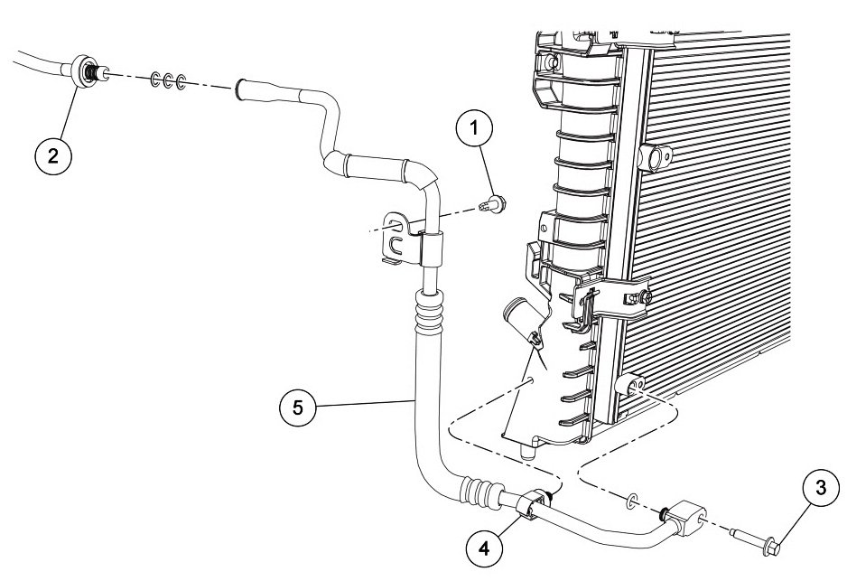
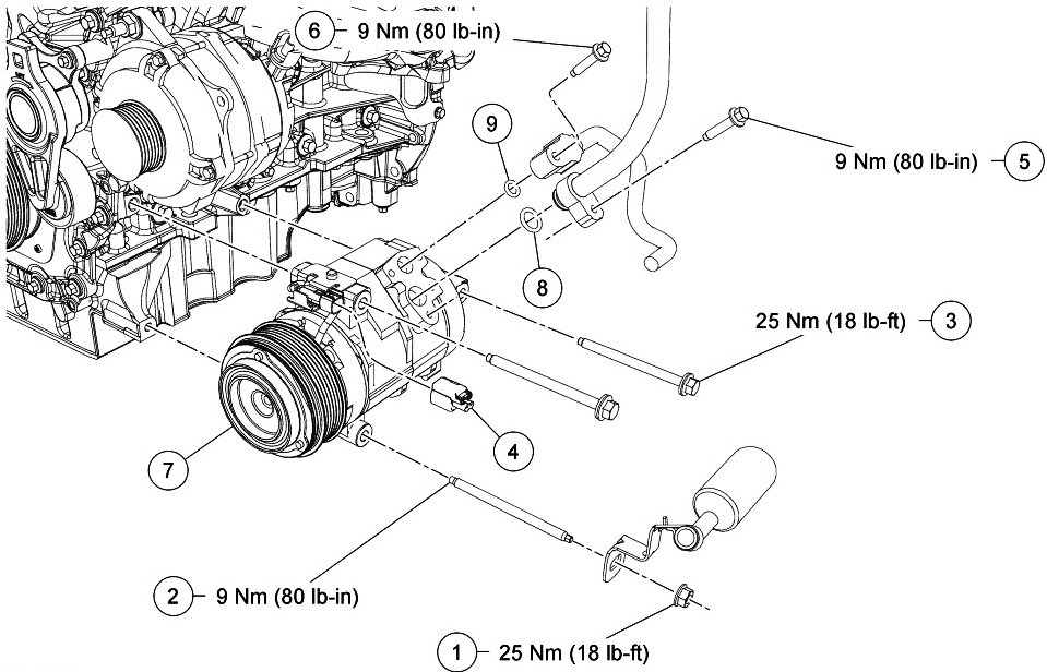
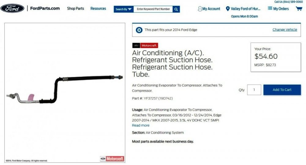
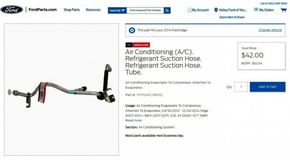
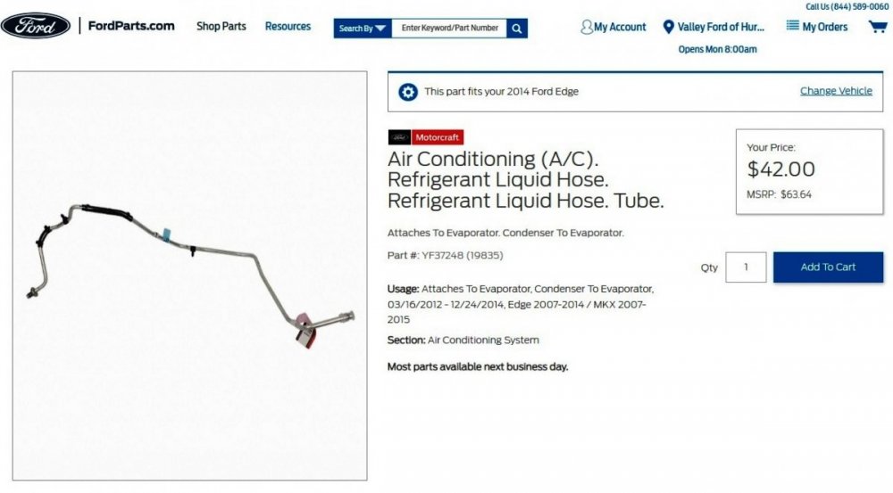
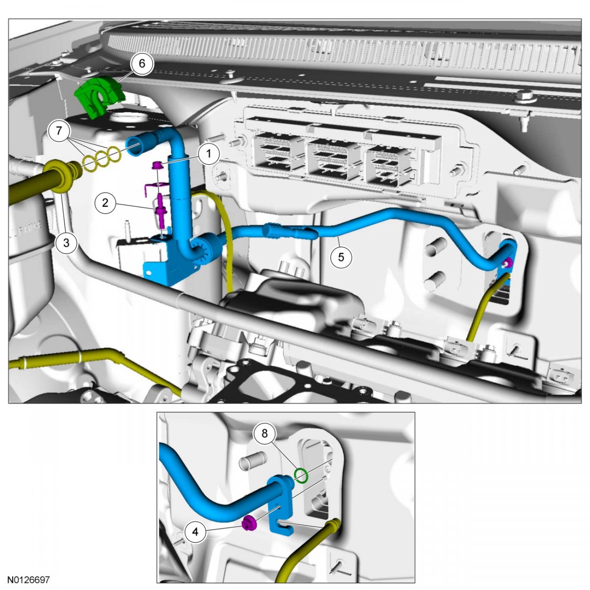
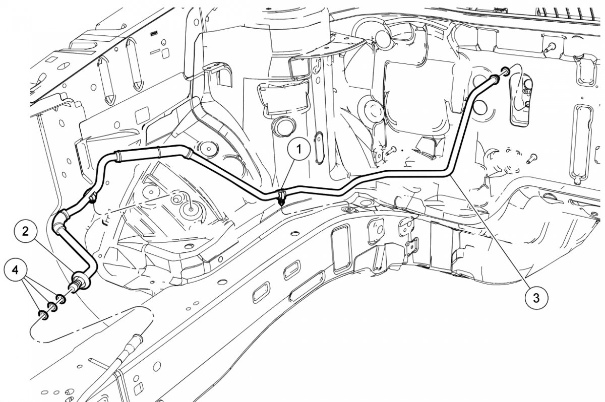
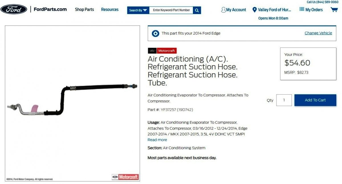
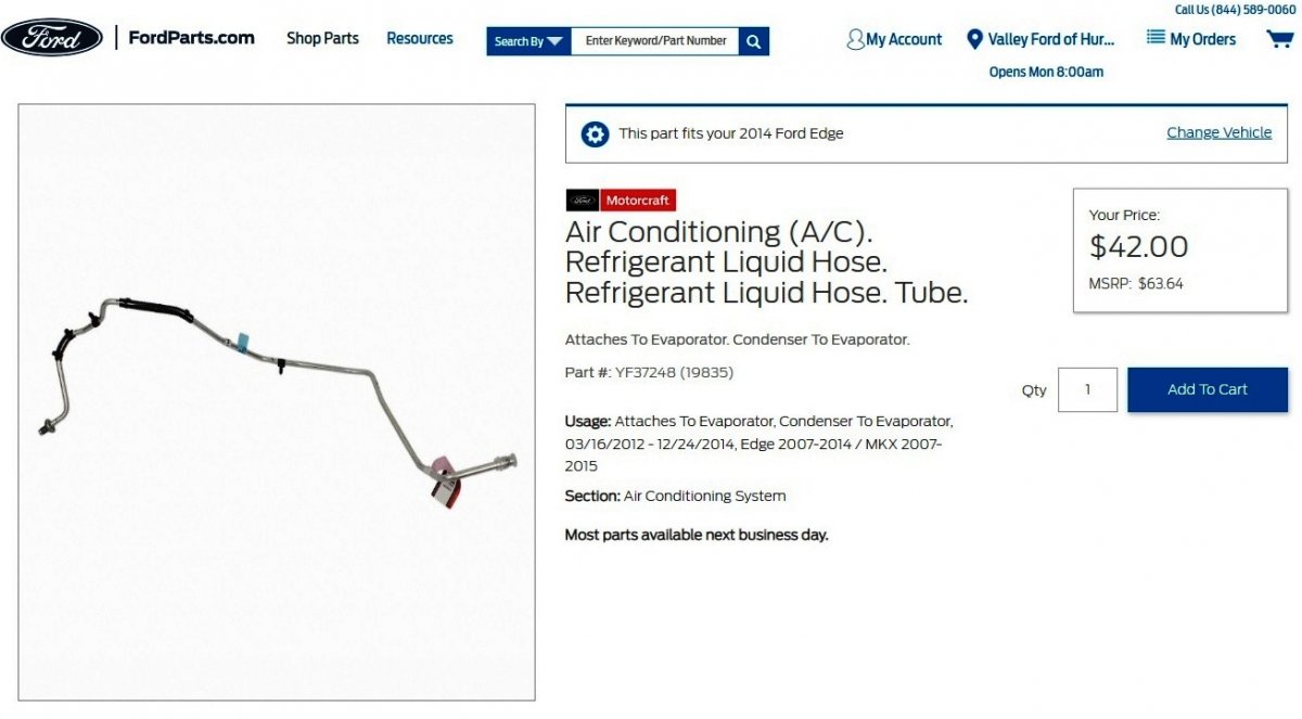
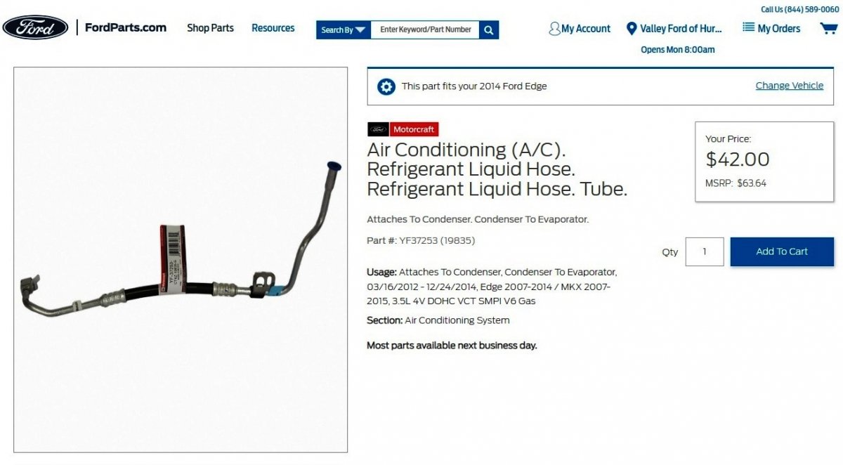
Welcome to the Forum, Mardogs! dabangsta is correct that there are two 2-piece line components conveying refrigerant to and from your Edge's A/C Evaporator... Condenser-Side Condenser-to-Evaporator Line Item Part Number Description 1 W707399 Condenser-to-evaporator line bracket bolt 2 — Condenser-to-evaporator line spring lock coupling (part of 19835) 3 W500215 Condenser outlet fitting bolt 4 W704005 Condenser-to-evaporator line radiator clip 5 19835 Condenser side condenser-to-evaporator line Link this Ford parts website page Evaporator-Side Condenser-to-Evaporator Line Item Part Number Description 1 19D721 Condenser-to-evaporator line clip (2 required) 2 — Condenser-to-evaporator line spring lock coupling (part of 19835) 3 19835 Evaporator side condenser-to-evaporator line 4 19E889 O-ring seal (4 required) Link this Ford parts website page Evaporator-Side Evaporator-to-Compressor Line Item Part Number Description 1 W520413 Ground strap nut 2 N806925 Evaporator outlet line bracket stud bolt 3 — Evaporator outlet line spring lock coupling (part of 19835) 4 W707142 Thermostatic Expansion Valve (TXV) fitting nut 5 19835 Evaporator outlet line 6 19E746 Spring lock coupling secondary latch 7 19E889 O-ring seal (3 required) 8 19E889 O-ring seal Link this Ford parts website page Compressor-Side Evaporator-to-Compressor Line Item Part Number Description 1 W520413 A/C compressor nut 2 W712610 A/C compressor stud 3 W712611 A/C compressor bolt (2 required) 4 12B637 Clutch field coil electrical connector 5 W500215 A/C compressor suction fitting bolt 6 W500215 A/C compressor discharge fitting bolt 7 19703 A/C compressor 8 19E889 Compressor suction fitting O-ring seal 9 19E889 Compressor discharge fitting O-ring seal Link this Ford parts website page Because you've already had a dealer diagnose your Edge's air conditioning issue, and you are not experienced in A/C systems, perhaps you are interested in price-shopping, to ensure that your dealer is being fair to you on the cost of the part(s) you're going to have them replace. If so, the above-pictured webpages are from Ford's own online parts-selling site, though the discounted pricing shown varies by dealer -- in this case, the dealer in my area that I designated offers discount pricing. Other dealers in my area charge list price for parts they supply and install. I mention this because you can use the FordParts website to survey pricing among your local Ford dealers to see if the dealer you may be prepared to do the repair will price-match the discounted parts pricing of a nearby dealer, or another online parts seller. On the other hand, maybe you're prepared to buy the needed part(s) -- which clearly you don't know what you need at the moment, but you can determine that from the dealer. If a problem develops with the part(s) you supply, then it's you -- and not the dealer -- who will be returning the part(s) and possibly paying installation & removal labor cost, since it wasn't the dealer who supplied the faulty or incorrect part(s). I had the fortunate experience of deciding to have my dealership supply an upgraded radiator for my MKX, which arrived and was a leaker out-of-the-box. I was uninvolved while the dealer had to order another radiator, drain the installed coolant, remove the faulty radiator, and complete the radiator upgrade work after the second upgrade radiator arrived. For me, paying the dealer a few more dollars for the upgraded radiator was worth it. Please report back on how things work out for you and your Edge. Good luck!


-
AM Band on Radio Has Ticking Sound
Haz replied to Dmtaurus's topic in Audio, Backup, Navigation & SYNC
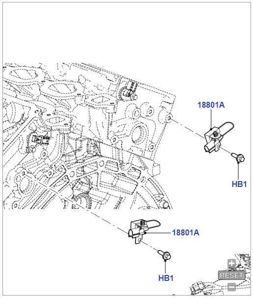
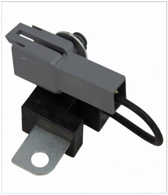
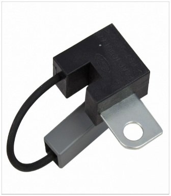
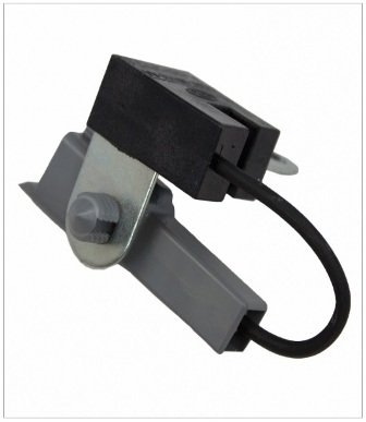
Looking to DILLARD000's 2008 model year, Ford's online parts site shows this listing for engine-mounted capacitors, though it indicates for Gen1/Gen1+ model years, but not for your 2015/Gen2 Edge... Good luck!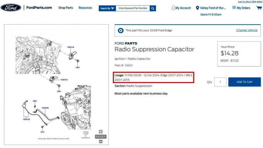
-
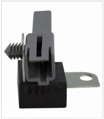
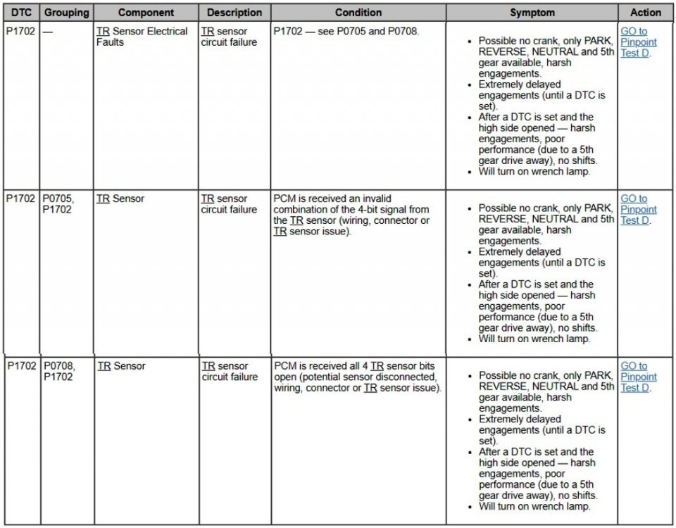
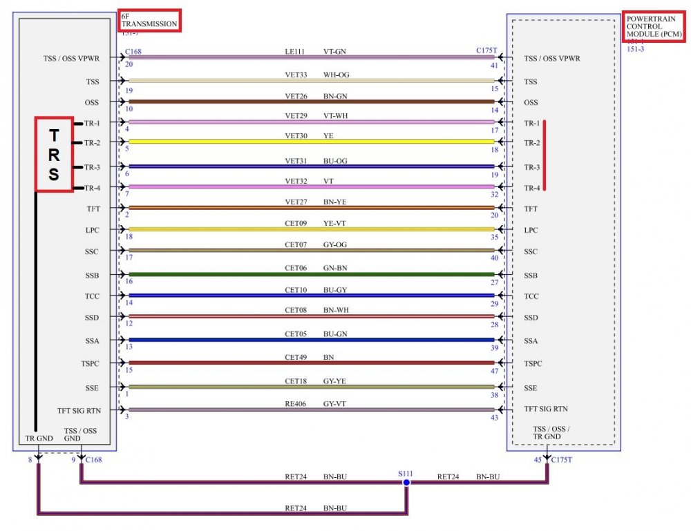
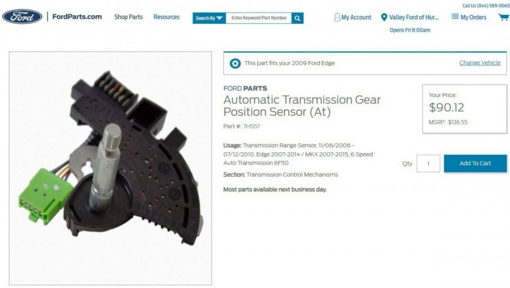
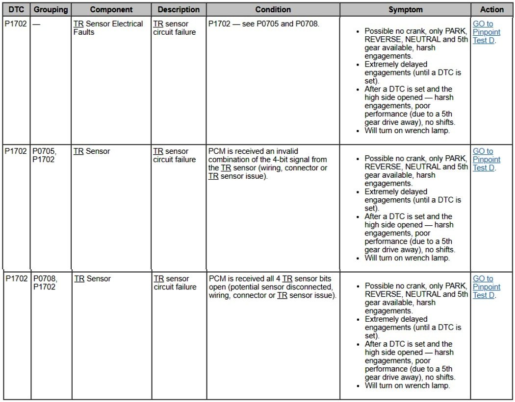
Per the Powertrain Diagnostic Trouble Code (DTC) chart in the 2009 Edge Workshop Manual, your Edge's behavior is consistent with P1702 Transmission Range Sensor circuit failure, which can limit transmission operation to Park, Neutral, Reverse, and 5th Gear only, with harsh engagements... The TR Sensor is internal to the transmission and it communicates with the Powertrain Control Module (PCM), per this TRS-augmented wiring diagram... The advice on how to proceed offered by Forum Moderator 1004ron is a large part of the Workshop Manual's Transmission Range Sensor Pinpoint Test D diagnostic procedure, which is supported by documents detailing Gear Selector Cable Adjustment, inspecting involved external electrical connectors, using an OBDII data link scan tool to monitor TR Sensor PIDs and evaluate TR Sensor & PCM operation, checking the PCM-TR Sensor wiring harness for open circuits and shorted to ground or power circuits. And if all these external tests yield no problems, then the final TR Sensor internal evaluation is conducted after prepping & opening the Transmission's Main Cover. Fulfilling all the external diagnostic steps ensures that you are not needlessly performing the rather extensive work of opening the transmission case to directly inspect & test the TR Sensor and its connector, as described in the TR Sensor Removal and Installation document. Should the TR Sensor fail its direct internal testing, Ford's online parts site offers this replacement... Document download links> 6F50 Transmission, 3.5L Duratec - Electronic Controls Wiring Diagram - 2009 Edge Workshop Manual.pdf Transmission Range Sensor - Pinpoint Test D - 2009 Edge Workshop Manual.pdf 6F50 Transmission - Selector Lever Cable Adjustment - 2009 Edge Workshop Manual.pdf 6F50-6F55 Transmission - Selector Lever Cable Adjustment - 2014 Edge Workshop Manual.pdf 6F50 Transmission, 3.5L Duratec - Electronic Controls Connector C168 Details - 2009 Edge Workshop Manual.pdf 6F50 Transmission, 3.5L Duratec - Electronic Controls Connector C168 Location - 2009 Edge Workshop Manual.pdf POWERTRAIN CONTROL MODULE (PCM) - Connector C175T Details - 2009 Edge.pdf POWERTRAIN CONTROL MODULE (PCM) - Connector C175T Location - 2009 Edge.pdf Powertrain Control Module (PCM) - For Firewall Location Illustration - 2009 Edge Workshop Manual.pdf Transmission Range (TR) Sensor - Removal and Installation - 2009 Edge Workshop Manual.pdf Transmission Range (TR) Sensor Connector Details Pin Number Circuit Function 1 Transmission Range (TR) Ground 2 TR 4 3 TR 3 4 TR 2 5 TR 1 6 Empty Solenoid Body-to-Transmission Range (TR) Sensor Internal Circuit Diagram Connector Details Solenoid Body Main Connector Pin Number TR Sensor Pin Number Circuit Function 4 5 Transmission Range (TR) 1 5 4 TR 2 6 3 TR 3 7 2 TR 4 8 1 TR Ground — 6 Empty You may want to review the documents, and your available tools -- including a scanner and multimeter for the diagnostics, and perhaps get a price for TR Sensor diagnosis, removal & replacement, and then make the decision on how you might proceed. Good luck!
SensorConnectorIllustration.jpg.96b58f77e8ff8d878e2d767ef931dfef.jpg)
SensorInternalCircuitDiagramConnectorsIllustration.jpg.b3d574293ba0fffad81b1c4d6c7992ea.jpg)
-
AM Band on Radio Has Ticking Sound
Haz replied to Dmtaurus's topic in Audio, Backup, Navigation & SYNC
On the 2015 Edge, for all engines, the Powertrain Control Module (PCM) grounds terminate underhood on the vehicle's right hand side at G110, per the below wiring diagram and wiring location illustration... Good luck!-GroundsTerminateatG110-WiringDiagram-2015Edgeallengines.thumb.jpg.8d004a9038d835898be928da8e9d5704.jpg)
-GroundsTerminateatG110-LocationIllustration-2015Edgeallengines.thumb.jpg.391336d3418b8795e7ee5ce7d4a389b5.jpg)
-
Your Edge certainly developed an odd confluence of symptoms. Congratulations on finding a knowledgeable technician to successfully address the issues. Good luck!
-
AM Band on Radio Has Ticking Sound
Haz replied to Dmtaurus's topic in Audio, Backup, Navigation & SYNC
Partial diagnostic test from the 2015 Edge Workshop Manual, and supplemental document download links below... PINPOINT TEST A: POOR RECEPTION OR CONTINUOUS SEEK OR SCAN - AM (AMPLITUDE MODULATION) / FM (FREQUENCY MODULATION) A1 CHECK THE AUDIO SYSTEM RECEPTION WITH THE ENGINE RUNNING Operate the audio system in AM / FM mode. Check the reception with the engine running, and with the engine off. Is poor reception only present with the engine running? Yes GO to A2 No GO to A4 A2 CHECK THE GENERATOR Ignition OFF. NOTICE: Do not allow the generator B+ cable terminal to make contact with a conductive surface. Failure to follow this instruction may result in personal injury or damage to the vehicle. Disconnect: Generator B+ Cable C102C. (3.5L Duratec shown, 2.0L EcoBoost similar) Start the engine. Operate the audio system in AM / FM mode. Is the reception OK? Yes INSTALL a new generator. • For vehicles with the 2.0L EcoBoost (184kW/250PS), REFER to: Generator - 2.0L EcoBoost (184kW/250PS) – MI4 (414-02 Generator and Regulator, Removal and Installation). • For vehicles with the 2.7L EcoBoost (238kW/324PS), REFER to: Generator - 2.7L EcoBoost (238kW/324PS) (414-02 Generator and Regulator, Removal and Installation). • For vehicles with the 3.5L Duratec (212kW/278PS), REFER to: Generator - 3.5L Duratec (212kW/278PS) (414-02 Generator and Regulator, Removal and Installation). No GO to A3 A3 CHECK THE IGNITION CIRCUITS Ignition OFF. Connect: Generator B+ Cable C102C. (3.5L Duratec shown, 2.0L EcoBoost similar) Visually inspect the engine compartment and make sure all ignition coils are correctly and securely connected, and that there are no visible cracks in the coil housings. Inspect all the wiring harnesses and connectors for damaged insulation and loose or broken conditions. Are the ignition components OK? Yes USE a jumper cable to temporarily ground various parts of the vehicle (examples include: engine, fenders, quarter panels, body sheet metal) to the frame. When the noise is eliminated, PROVIDE a permanent ground where necessary. No REPAIR the ignition system as necessary. Document download links> Ignition Coil-On-Plug - Removal and Installation - 2.0L EcoBoost - 2015 Edge Workshop Manual.pdf Ignition Coil-On-Plug - Removal and Installation - 3.5L Duratec - 2015 Edge Workshop Manual.pdf Good luck!

-
Document download links> Air Cleaner Outlet Pipe - Removal and Installation - 2.0L EcoBoost - 2016 Edge Workshop Manual.pdf Heated Oxygen Sensor (HO2S) - Removal and Installation - 2.0L EcoBoost - 2016 Edge Workshop Manual.pdf Catalyst Monitor Sensor - Removal and Installation - 2.0L EcoBoost - 2016 Edge Workshop Manual.pdf Heated Oxygen Sensor (HO2S) - Wiring Diagram - 2.0L EcoBoost - 2016 Edge Workshop Manual.pdf Heated Oxygen Sensor (HO2S) - Connectors C1631 & C1632 Locations - 2.0L EcoBoost - 2016 Edge Workshop Manual.pdf Universal Heated Oxygen Sensor (HO2S) #11 - Connector C1631 Details - 2.0L EcoBoost - 2016 Edge Workshop Manual.pdf Heated Oxygen Sensor (HO2S) #12 - Connector C1632 Details - 2.0L EcoBoost - 2016 Edge Workshop Manual.pdf Powertrain Control Module (PCM) - Connector C1361B Details - 2.0L EcoBoost - 2016 Edge.pdf Heated Oxygen Sensor (HO2S) - Description and Operation - Ford Powertrain Control-Evaporative Diagnosis Manual - 2016 Gasoline.pdf TSB 18-2212 - 2.0L EcoBoost - Illuminated Malfunction Indicator Lamp (MIL) with Diagnostic Trouble Code (DTC) P0036 - Built On Or Before 12-Mar-2018.pdf Rear Driveshaft - Removal and Installation - 2016 Edge Workshop Manual.pdf Muffler and Tailpipe - Removal and Installation - 2.0L EcoBoost - 2016 Edge Workshop Manual.pdf Good luck!
-
Document download links> Camshaft Position Sensors - Wiring Diagram - 3.5L - 2008 Edge.pdf Powertrain Control Module (PCM) - Connector C175E Details - 3.5L - 2008 Edge.pdf Powertrain Control Module (PCM) - Connector C175E Location - 3.5L - 2008 Edge.pdf Camshaft Position Sensors - Inline Connectors C139 Male & Female Details - 3.5L - 2008 Edge.pdf Camshaft Position Sensors - Inline Connectors C139 Male & Female Location - 3.5L - 2008 Edge.pdf Camshaft Position Sensors - Inline Connectors C139 + Camshaft Sensor Locations - 3.5L - 2008 Edge.pdf Good luck!
-
Welcome to the Forum, Booker ! Document download links> 6-Speaker Audio Wiring Diagram - 2019 Edge.pdf 9-Speaker Audio Wiring Diagram #1 - 2019 Edge.pdf 9-Speaker Audio Wiring Diagram #2 - 2019 Edge.pdf 12-Speaker Audio Wiring Diagram #1 - 2019 Edge.pdf 12-Speaker Audio Wiring Diagram #2 - 2019 Edge.pdf 12-Speaker Audio Wiring Diagram #3 - 2019 Edge.pdf 12-Speaker Audio Wiring Diagram #4 - 2019 Edge.pdf AUDIO FRONT CONTROL MODULE (ACM) - Connector C240A Details - 2019 Edge.pdf AUDIO FRONT CONTROL MODULE (ACM) - Connector C240A Location - 2019 Edge.pdf Good luck!
-
Welcome to the Forum, fcasontoo ! Please be aware that some procedural instructions in the following document may appear on the page preceding the illustration relating to the described action-step... Document download links> Generator - 2.0L EcoBoost - Removal and Installation - 2019 Edge Workshop Manual.pdf Air Conditioning Compressor Belt - 2.0L EcoBoost - Removal and Installation - 2019 Edge Workshop Manual.pdf Battery Disconnect and Connect - General Procedures - 2019 Edge Workshop Manual.pdf Good luck!
-
One additional document download link, to supplement the files shared offline... Cabin Heater Coolant Pump - 2.0L EcoBoost - Removal and Installation - 2015 Edge Workshop Manual.pdf Good luck!
-
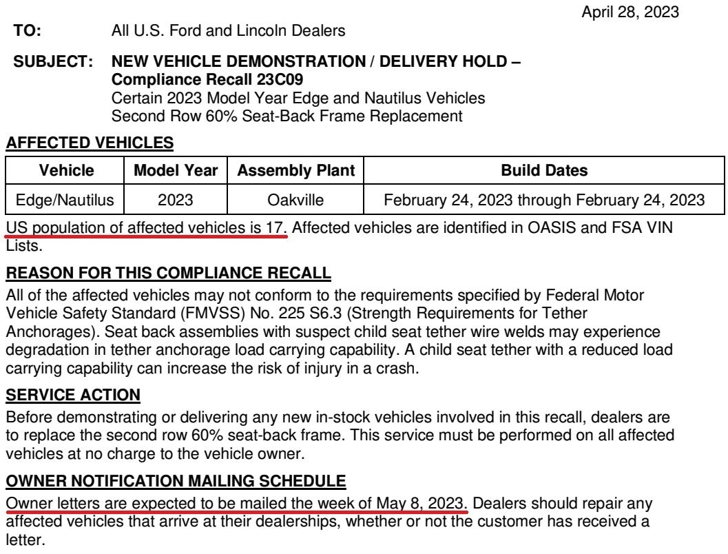
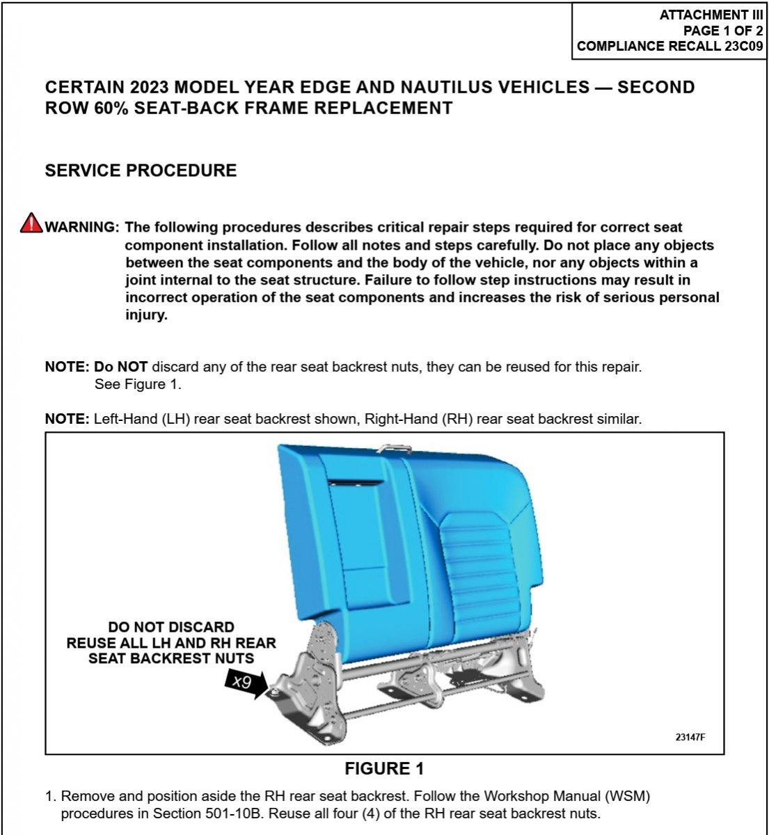
Dealer bulletin and technical repair info released, affected population reduced to 17 vehicles...


- 1 reply
-
- 3
-
-
You may want to consider submitting a sample of the drained engine oil to Blackstone Labs, to see how much and what types of metal it may contain. Forum member macbwt has many informative oil testing videos on his MACTFordEdge YouTube page. Good luck!
-
These documents may also be helpful... Power Distribution-BCM - Wiring Diagram - Cell 013, Page 2 - 2012 Edge Workshop Manual.pdf COOLING FAN MODULE - Wiring Diagram - 2012 Edge Workshop Manual.pdf COOLING FAN MODULE - Connector C1554 Details - 2012 Edge Workshop Manual.pdf COOLING FAN MODULE - Connector C1554 Locator - 2012 Edge Workshop Manual.pdf Cooling Fan and Shroud - 3.5L, 3.7L - 2012 Edge Workshop Manual.pdf Good luck!
-
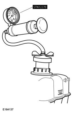
Welcome to the Forum, JayTheWorldsHero! TSB 22-2229 - 2015-2018 Edge + Other Models, 2.0L EcoBoost - Coolant In Cylinders, White Exhaust Smoke And_Or Illuminated MIL.pdf (document download link) describes these various applicable warranty coverages... Warranty Status: Eligible under provisions of New Vehicle Limited Warranty (NVLW)/Emissions Warranty/Service Part Warranty (SPW)/Special Service Part (SSP)/Extended Service Plan (ESP) coverage. Limits/policies/prior approvals are not altered by a TSB. NVLW/Emissions Warranty/SPW/SSP/ESP coverage limits are determined by the identified causal part and verified using the OASIS part coverage tool. For repairs covered by the NVLW, completion of the procedure outlined in this TSB does not require obtaining Prior Approval or completion of a Cost Cap. Your Edge's 7-year/100,000 miles Certified Pre-Owned (CPO) Powertrain coverage falls under the TSB's "Extended Service Plan (ESP)" coverage category, and your Edge's CPO Powertrain generic covered- parts list should be... Engine: Cylinder block and internal lubricated parts, seals and gaskets, the cylinder heads, manifold (exhaust, intake and bolts), factoryinstalled turbocharger/supercharger units, timing chain (gears or belt), fywheel, valve covers, oil pan, timing chain cover, oil pump, water pump, thermostat, thermostat housing. (Exceptions: fuel injection components are not covered.) Transmission: Transmission case and all internal parts, including torque converter and transfer case (all internal parts), seals, gaskets and transmission control module. Front-Wheel Drive: Front drive housing and rear axle housing for AWD (including all internal parts), universal and constant velocity joints, axle shafs, locking rings (four-wheel-drive vehicles), seals and gaskets, and automatic front locking hubs (four-wheel drive). Rear-Wheel Drive: Drive axle housings and front axle housing for 4x4 (including all internal parts), universal and constant velocity joints, axle shafts, seals and gaskets, and driveshafts. As dabangsta mentioned, a 5-hour coolant system pressure test exhibiting a 4 psi leak-down is among the TSB's necessary qualifying symptoms. If you're a curious do-it-yourself owner -- or your dealer's Service scheduling is seriously backed up -- your neighborhood auto parts store may offer a cooling system pressure tester through their tool loaning program that may require a refundable deposit equal to the tool's full purchase price. If that interests you, the following is Ford's procedure from the 2018 Edge Workshop Manual... Cooling System Pressure Test WARNING: Always allow the engine to cool before opening the cooling system. Do not unscrew the coolant pressure relief cap when the engine is operating or the cooling system is hot. The cooling system is under pressure; steam and hot liquid can come out forcefully when the cap is loosened slightly. Failure to follow these instructions may result in serious personal injury. NOTE: Vehicles have a pressure relief cap on the degas bottle and no radiator cap. Turn the engine OFF. Check the engine coolant level and adjust as necessary. Remove the degas bottle cap. Inspect the degas bottle cap and degas bottle for any issues that would cause improper sealing, such as for cross-threading, burrs, damaged o-ring, etc. If any issues are found, INSTALL a new cap and/or degas bottle. Attach the Pressure Tester (Stant 12270 or equivalent) and adaptor (Snap-On TA53 or equivalent), to the degas bottle cap. The cap must hold pressure of 145 kPa +/- 21 kPa (21 PSI +/- 3 PSI). If any issues are found, INSTALL a new cap. Attach the Pressure Tester (Stant 12270 or equivalent) and adaptor (Snap-On TA52, AST ASSFZ-47, Redline RDL95-0750 or equivalent) to the degas bottle. NOTICE: Do not pressurize the cooling system beyond the maximum pressure listed in the specifications table in this section, or cooling system components can be damaged. NOTE: If the plunger of the pressure tester is pressed too fast, an erroneous pressure reading will result. To pressurize the engine cooling system, slowly press the plunger of the pressure test pump and increase the pressure to between 124 - 138 kPa (18 - 20 PSI). Observe the gauge reading for approximately 2 minutes. Pressure should not drop during this time. If the pressure drops within this time, inspect for leaks and repair as necessary. Allow the vehicle to sit for a minimum of 5 hours, or overnight. NOTE: 2-4 psi of pressure drop is normal and expected after engine cool down. If the pressure drops more than the expected range of 2-4 psi and no leaks are found and the pressure drops, the leak may be internal to the engine. Inspect the coolant for engine oil and the engine oil for coolant. REFER to: Engine (303-00 Engine System - General Information, Diagnosis and Testing). If the pressure does not drop, remove the cooling system Pressure Tester and adaptor from degas bottle. Install the degas bottle cap until it contacts the hard stop. And finally, before your Edge reaches its CPO 100,000 mile Powertrain coverage limit, you have the opportunity to renew with FordProtect PowertrainCare coverage without any inspection requirement. Document download links> Cooling System Pressure Test - 2018 Edge Workshop Manual.pdf Ford Certified Pre-Owned (CPO) Consumer Brochure - October 2018.pdf FordProtect PowertrainCARE Brochure - October 2022.pdf Good luck!
-
Adding Adaptive suspension to my ST
Haz replied to johnmarkp's topic in Brakes, Chassis & Suspension
The Vehicle Dynamics Control Module (VDM) processes an impressive array of inputs to do its job... Document download links> Vehicle Dynamic Suspension - System Operation and Component Description - 2019 Nautilus Workshop Manual.pdf Vehicle Dynamic Suspension - Component Location - 2019 Nautilus Workshop Manual.pdf Vehicle Dynamic Suspension - Wiring Diagram, Cell 041 Page 1 - 2019 Nautilus Workshop Manual.pdf Vehicle Dynamic Suspension - Wiring Diagram, Cell 041 Page 2 - 2019 Nautilus Workshop Manual.pdf Vehicle Dynamic Suspension - Wiring Diagram, Cell 041 Page 3 - 2019 Nautilus Workshop Manual.pdf Vehicle Dynamics Control Module (VDM) - Connector C4396C Details - 2019 Nautilus Workshop Manual.pdf Vehicle Dynamics Control Module (VDM) - Connector C4396D Details - 2019 Nautilus Workshop Manual.pdf Vehicle Dynamics Control Module (VDM) - Connectors C4396C & C4396D Location - 2019 Nautilus Workshop Manual.pdf Vehicle Dynamics Control Module (VDM) - Removal and Installation - 2019 Nautilus Workshop Manual.pdf Vehicle Dynamic Suspension - Diagnosis and Testing - 2019 Nautilus Workshop Manual.pdf Front Suspension Height Sensor - Removal and Installation - 2019 Nautilus Workshop Manual.pdf Front Strut and Spring Assembly - Removal and Installation - 2019 Nautilus Workshop Manual.pdf Rear Suspension Height Sensor - Removal and Installation - 2019 Nautilus Workshop Manual.pdf Rear Shock Absorber - Removal and Installation - 2019 Nautilus Workshop Manual.pdf Good luck! -
Windshield Replacement
Haz replied to 1004ron's topic in Glass, Lenses, Lighting, Mirrors, Sunroof (BAMR), Wipers
The 2015-2023 Edge Workshop Manuals all provide a single, generalized Fixed Glass procedure, carrying a 11/21/2019 revision date... Document download links> Fixed Glass - General Procedures - 2017 Edge Workshop Manual.pdf Interior Rear View Mirror - Removal and Installation - 2017 Edge Workshop Manual.pdf Image Processing Module A (IPMA) Camera Heated Windshield Element - Removal and Installation - 2017 Edge Workshop Manual.pdf A-Pillar Trim Panel - Removal and Installation - 2017 Edge Workshop Manual.pdf B-Pillar Trim Panel - Removal and Installation - 2017 Edge Workshop Manual.pdf Headliner, Lowering - Removal and Installation - 2017 Edge Workshop Manual.pdf Good luck!


-GroundsTerminateatG110-WiringDiagram-2015Edgeallengines.jpg.0b8e648db4546e74089714c889d5f524.jpg)
-GroundsTerminateatG110-LocationIllustration-2015Edgeallengines.jpg.cbaf00cc01fe679dcaf80ce030732478.jpg)