


Haz
-
Posts
1,476 -
Joined
-
Last visited
-
Days Won
395
Content Type
Profiles
Forums
Gallery
Everything posted by Haz
-
2007 Edge Coolant reservior hose changeout
Haz replied to SD40-2's topic in Alarms, Keyless Entry, Locks & Remote Start
@SD40-2: Because the 2007 Edge Workshop Manual does not offer specific procedures for coolant hose replacement, attached below as PDF documents are Cooling System sections that may provide you insights toward your desired outcome... Good luck! Cooling System Draining, Filling and Bleeding - General Procedures - 2007 Edge Workshop Manual.pdf Radiator - Removal and Installation - 2007 Edge Workshop Manual.pdf Degas Bottle - Removal and Installation - 2007 Edge Workshop Manual.pdf Engine Cooling - Description and Operation - 2007 Edge Workshop Manual.pdf Engine Cooling - Specifications - 2007 Edge Workshop Manual.pdf Cooling Fan Motor and Shroud - Removal and Installation - 2007 Edge Workshop Manual.pdf Engine Cooling - Diagnosis and Testing - 2007 Edge Workshop Manual.pdf Thermostat - Removal and Installation - 2007 Edge Workshop Manual.pdf Intake Air System Components — Exploded View - Removal and Installation - 2007 Edge Workshop Manual.pdf Air Cleaner Outlet Pipe - Removal and Installation - 2007 Edge Workshop Manual.pdf Thermostat Housing - Removal and Installation - 2007 Edge Workshop Manual.pdf -
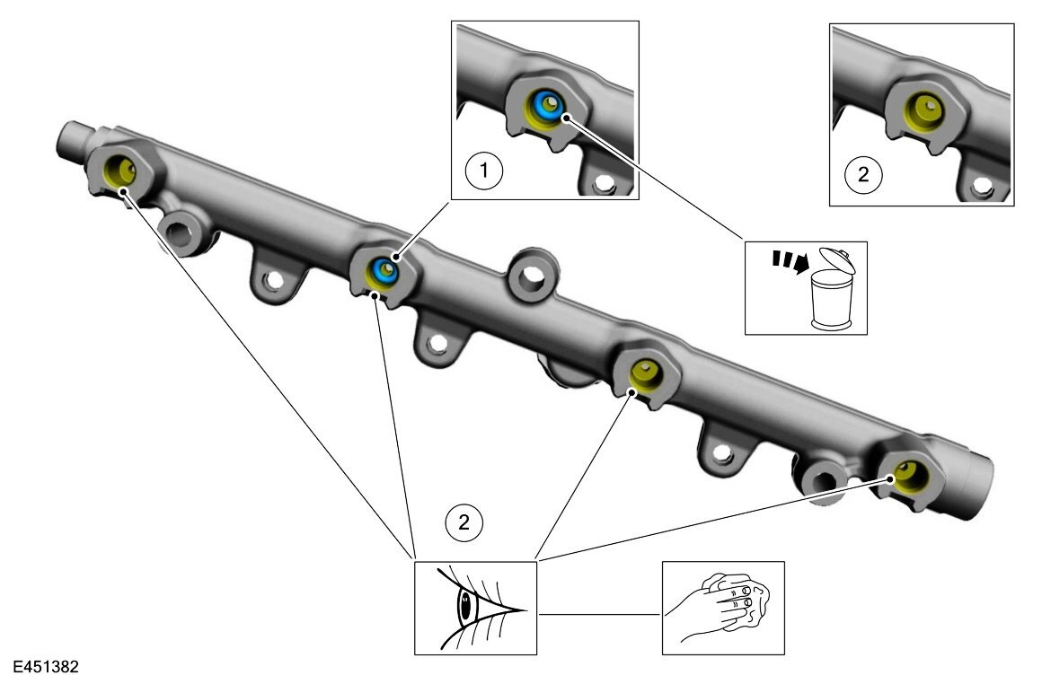
SSM 53443 2024-2025 Nautilus - Direct Injection Fuel Injector Removal Or Replacement 2024-2025 Nautilus vehicles require inspection and removal and discard of O-rings or debris that may be stuck in the direct injection fuel rail injector bores when removing or replacing the injectors for any reason. Workshop Manual (WSM), Section 303-04 Direct Fuel Injection Rail Removal and Installation has been updated to address this condition. The revised step from the referenced Workshop Manual removal and installation procedure... NOTICE: Check the fuel rail at fuel injector seating area for any sign of O-ring or its debris is present. Remove the O-ring and clean the injector bores. Inspect the fuel rail for any O-ring stuck in the injector bore. Remove O-ring. Clean the injector bores.

-
Welcome to the Forum @Killacam714! Model Year ? Edge, MKX, or Nautilus ? Trim Level ? Engine: 3.5L or 3.7L Duratec or 2.0L or 2.7L EcoBoost ? Good luck!
-
Welcome to the Forum @Shanejohn13! Attached below as PDF documents are Roof Opening Panel Front Trim removal & installation procedures for 2007-2014 Edge, 2015-2017 Edge, and 2018-2024 Edge... Good luck! Roof Opening Panel Trim — Front - Removal and Installation - 2007-2014 Edge Workshop Manual.pdf Roof Opening Panel Front Trim - Removal and Installation - 2015-2017 Edge Workshop Manual.pdf Roof Opening Panel Front Trim - Removal and Installation - 2018-2024 Edge Workshop Manual.pdf
-
Problem with camera heating
Haz replied to Iroga's topic in Glass, Lenses, Lighting, Mirrors, Sunroof (BAMR), Wipers
The following information applies to 2019-2024 Edges, and most of it is different from the previously posted 2015-2018 Edge documents. @Iroga: While you have indicated no Diagnostic Trouble Codes (DTCs) are present in the Image Processing Module A (IPMA), it may be useful for you to perform diagnostic Pinpoint Test C to assess the circuits and modules involved with the Camera Windshield Defrost Heater operation, especially noting this guidance... NOTE: Before replacing the camera windshield defrost heater, windshield or IPMA for a camera windshield defrost heater concern, verify the integrity of the wiring, connectors and terminals on the camera windshield defrost heater jumper harness. Lane Keeping Symptom Chart (partial) Diagostic Trouble Codes DTC B120C:11, DTC B120C:13 Refer to Wiring Diagram for schematic and connector information. Normal Operation and Fault Conditions The IPMA supplies voltage and ground to the camera windshield defrost heater. The IPMA uses input from the front camera and the ambient air temperature data from the PCM to command the heater on and off. The heater may be commanded on if the ambient temperature is below 5°C (41°F). Possible Causes Wiring, terminals or connectors Camera windshield defrost heater IPMA DTC Fault Trigger Conditions DTC Description Fault Trigger Conditions B120C:11 Heater for Windshield Mounted Sensor: Circuit Short To Ground An on-demand and continuous memory DTC that sets in the IPMA if an excessive current draw is detected on the heater output circuit. B120C:13 Heater for Windshield Mounted Sensor: Circuit Open An on-demand and continuous memory DTC that sets in the IPMA if a lower than expected current draw is detected on the heater output circuit. Visual Inspection and Diagnostic Pre-Checks Inspect the integrity of the wiring, terminals and connectors on the jumper harness between the vehicle harness and the camera windshield defrost heater. PINPOINT TEST C DTC (DIAGNOSTIC TROUBLE CODE) B120C:11, DTC (DIAGNOSTIC TROUBLE CODE) B120C:13 NOTICE: Use the correct probe adapter(s) when making measurements. Failure to use the correct probe adapter(s) may cause damage to the connector. Use only Rotunda Flex Probes (NUD105-R025D) NOTE: Before replacing the camera windshield defrost heater, windshield or IPMA for a camera windshield defrost heater concern, verify the integrity of the wiring, connectors and terminals on the camera windshield defrost heater jumper harness. C1 CHECK THE IPMA (IMAGE PROCESSING MODULE A) DIAGNOSTIC TROUBLE CODES (DTCS) Ignition ON. Using a diagnostic scan tool, perform the IPMA self-test. Is DTC B120C:11 or DTC B120C:13 present? Yes For DTC B120C:11, GO to C2 For DTC B120C:13, GO to C5 No The system is operating correctly at this time. INSPECT the connectors, wiring and the camera windshield defrost heater for damage or poor connections. C2 CHECK FOR SHORT TO GROUND WITH THE IPMA (IMAGE PROCESSING MODULE A) CAMERA HEATED WINDSHIELD ELEMENT DISCONNECTED Ignition OFF. Disconnect: Rain Sensor Module C914A. Ignition ON. Using a diagnostic scan tool, clear the IPMA Diagnostic Trouble Codes (DTCs). Perform the IPMA self-test. Is DTC B120C:11 present? Yes GO to C3 No INSTALL a new windshield. REFER to: Fixed Glass (501-11 Glass, Frames and Mechanisms, General Procedures). C3 CHECK THE IPMA (IMAGE PROCESSING MODULE A) CAMERA HEATED WINDSHIELD ELEMENT OUTPUT CIRCUIT FOR A SHORT TO GROUND Ignition OFF. Disconnect: IPMA C9224. Measure: Positive Lead Measurement / Action Negative Lead C9224 Pin 8 Ground Is the resistance greater than 10,000 ohms? Yes GO to C4 No REPAIR the circuit. After the repair, CLEAR the DTC , CYCLE the ignition, and RUN the IPMA on-demand self-test to re-enable the circuit. C4 CHECK IPMA (IMAGE PROCESSING MODULE A) CAMERA HEATED ELEMENT CIRCUITS FOR A SHORT TOGETHER Measure: Positive Lead Measurement / Action Negative Lead C9224 Pin 8 C9224 Pin 1 Is the resistance greater than 10,000 ohms? Yes GO to C5 No REPAIR the circuits. After the repair, CLEAR the DTC , CYCLE the ignition, and RUN the IPMA on demand self-test to re-enable the circuit. C5 CHECK FOR DTC (DIAGNOSTIC TROUBLE CODE) B120C:13 WITH THE IPMA (IMAGE PROCESSING MODULE A) CAMERA HEATED ELEMENT CIRCUITS JUMPERED TOGETHER Ignition OFF. Disconnect: Rain Sensor Module C914A. Connect: Lead 1 Measurement / Action Lead 2 C914A Pin 1 C914A Pin 3 Ignition ON. Using a diagnostic scan tool, clear the IPMA Diagnostic Trouble Codes (DTCs). Perform the IPMA self-test. Is DTC B120C:11 present? Yes REMOVE the fused jumper wire. INSTALL a new windshield. REFER to: Fixed Glass (501-11 Glass, Frames and Mechanisms, General Procedures). No REMOVE the fused jumper wire. GO to C6 C6 CHECK THE IPMA (IMAGE PROCESSING MODULE A) CAMERA HEATED WINDSHIELD ELEMENT CIRCUITS FOR AN OPEN Ignition OFF. Disconnect: IPMA C9224. Measure: Positive Lead Measurement / Action Negative Lead C9224 Pin 8 C914A Pin 3 C9224 Pin 1 C914A Pin 1 Are the resistances less than 3 ohms? Yes GO to C7 No REPAIR the affected circuit. C7 CHECK FOR CORRECT IPMA (IMAGE PROCESSING MODULE A) OPERATION Disconnect and inspect all IPMA connectors and related in-line connectors. Repair: corrosion (install new connector or terminals - clean module pins) damaged or bent pins - install new terminals/pins pushed-out pins - install new pins as necessary Reconnect the IPMA connectors and related in-line connectors. Make sure they seat and latch correctly. Operate the system to determine if the concern is still present. Is the concern still present? Yes CHECK OASIS for any applicable Technical Service Bulletins (TSBs). If a TSB exists for this concern, DISCONTINUE this test and FOLLOW the TSB instructions. If no Technical Service Bulletins (TSBs) address this concern, INSTALL a new IPMA REFER to: Image Processing Module A (IPMA) (419-07 Lane Keeping System, Removal and Installation). No The system is operating correctly at this time. The concern may have been caused by module connections. ADDRESS the root cause of any connector or pin issues. Related information is attached below as PDF documents... Good luck! IMAGE PROCESSING MODULE A (IPMA) - Removal and Installation - 2019 Edge Workshop Manual.pdf Interior Rear View Mirror - Removal and Installation - 2019 Edge Workshop Manual.pdf Rain Sensor - Removal and Installation - 2019 Edge Workshop Manual.pdf Body Control Module (BCM) - Fuse F36 (15 amp) Location Red-Box Highlighted - 2019 Edge.pdf RAIN SENSOR - Heater Pwr-Gnd Circuits Depicted In This Wiring Diagram - 2019 Edge.pdf RAIN SENSOR - Connector C914A Location - 2019 Edge.pdf RAIN SENSOR - Connector C914A Pinout - 2019 Edge.pdf IMAGE PROCESSING MODULE A (IPMA) - Heater Pwr-Gnd Supplied Via Rain Sensor Conector C914 Pins 1 & 3 - Wiring Diagram - 2019 Edge.pdf IMAGE PROCESSING MODULE A (IPMA) - Power Distribution Wiring Diagram - 2019 Edge.pdf Rain Sensor, IPMA, Heater - Ground Termination G304 Location - 2019 Edge.pdf Rain Sensor, IPMA, Heater - Ground Splices S912 & S913 Location - 2019 Edge.pdf IMAGE PROCESSING MODULE A (IPMA) - Ground Wiring Diagram - 2019 Edge.pdf IMAGE PROCESSING MODULE A (IPMA) - Connector C9224 Pinout - 2019 Edge.pdf IMAGE PROCESSING MODULE A (IPMA) - Connector C9224 Location - 2019 Edge.pdf
-HeaterPwr-GndSuppliedViaRainSensorConectorC914Pins13-WiringDiagram-2019Edge.thumb.jpg.0684fb3d51c7ec4fbeb834cb56b733e0.jpg)


-
Problem with camera heating
Haz replied to Iroga's topic in Glass, Lenses, Lighting, Mirrors, Sunroof (BAMR), Wipers
Welcome to the Forum @Iroga! Absent you mentioning your Edge's model year, I pulled the following 2015-2018 Edge documents to supplement @Wubster100's research... Good luck! Body Control Module (BCM) - Fuse F36 (15 amp) Location Red-Box Highlighted - 2015 Edge.pdf Lane Keeping System - Component Location - Description and Operation - 2015 Edge Workshop Manual.pdf Body Control Module (BCM) - Fuse F36 (15 amp) Power Distribution Wiring Diagram - 2015 Edge.pdf Interior Rear View Mirror - Removal and Installation - 2015 Edge Workshop Manual.pdf Image Processing Module A (IPMA) Camera Heated Windshield Element - Removal and Installation - 2015 Edge Workshop Manual.pdf Body Control Module (BCM) - Conector-Fuse-Relay Locations Illustration - 2015 Edge.pdf AUTO-DIMMING INTERIOR MIRROR - Connector C9012 Loction- 2015 Edge.pdf AUTO-DIMMING INTERIOR MIRROR - Connector C9012 - 2015 Edge.pdf CAMERA WINDSHIELD DEFROST HEATER - Connectors C9048A & C9048B Loction - 2015 Edge.pdf CAMERA WINDSHIELD DEFROST HEATER - Connector C9048A - 2015 Edge.pdf CAMERA WINDSHIELD DEFROST HEATER - Connector C9048B - 2015 Edge.pdf IPMA-Camera Windshield Defrost Heater - Wiring Diagram - 2015 Edge.pdf -
Windshield Replacement
Haz replied to 1004ron's topic in Glass, Lenses, Lighting, Mirrors, Sunroof (BAMR), Wipers
@Wubster100: Requested information is attached below as PDF documents... Good luck! Rain Sensor Module - Connector C914 Pinout - 2021 Edge.pdf Rain Sensor Module - Connector C914 Location - 2021 Edge.pdf Rain Sensor Module - Power Distribution Wiring Diagram - 2021 Edge.pdf Rain Sensor Module - Grounds Wiring Diagram - 2021 Edge.pdf Rain Sensor Module with Adaptive Cruise - Wiring Diagram - 2021 Edge.pdf IMAGE PROCESSING MODULE A (IPMA) - Connector C9224 Pinout - 2021 Edge.pdf Rain Sensor Module - Wiring Diagram - 2021 Edge.pdf Wipers and Washers - Rain Sensor Wiring Diagram 81-2 Extension - 2021 Edge.pdf Wipers and Washers - Rain Sensor Wiring Diagram 81-1 Extension - 2021 Edge.pdf -
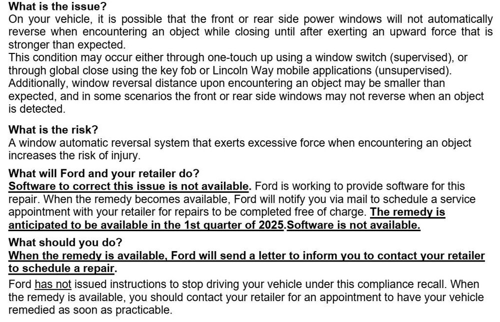
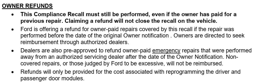
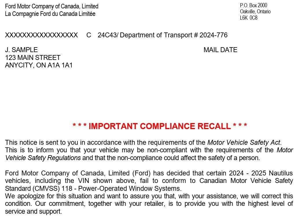
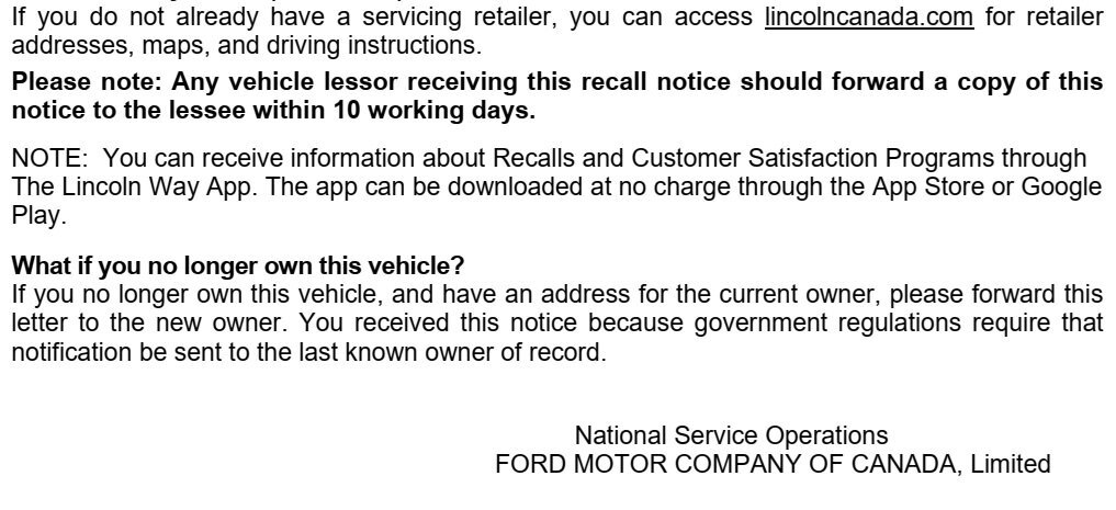
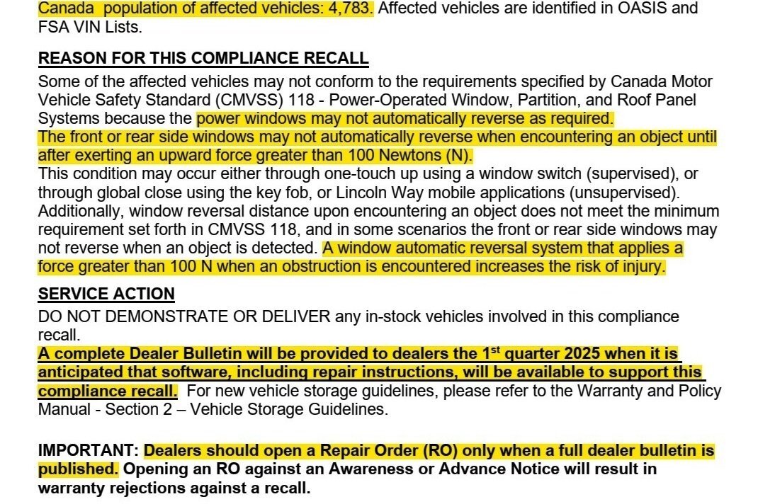
** The complete Canadian Dealer Bulletin and tentative Letter to Owners have been released. Technical Instructions are identical ** Tentative Letter To Owners


-
Good luck! 360 Camera - Wiring Diagram 2 - 2024 Edge - China.pdf 360 Camera - Wiring Diagram 1 - 2024 Edge - China.pdf Parking Aid - Component Location - Description and Operation - 2024 Edge Workshop Manual - China.pdf Side Parking Aid Camera - Removal and Installation - 2024 Edge Workshop Manual - China.pdf

-
Welcome to the Forum @RedMtDave! While their inventory status could be faulty, these online OEM Ford Parts sellers show a Right Hand and a Left Hand as being in stock and available to ship. Good luck!
-
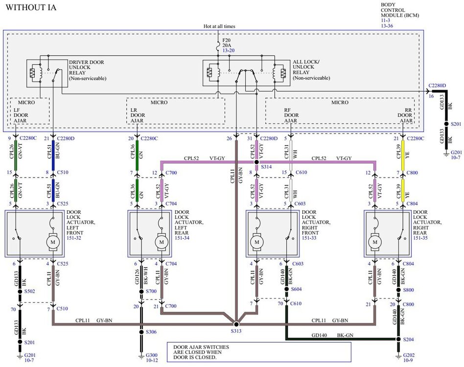
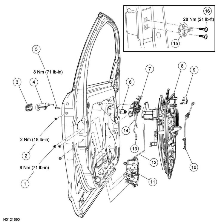
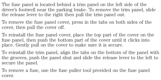
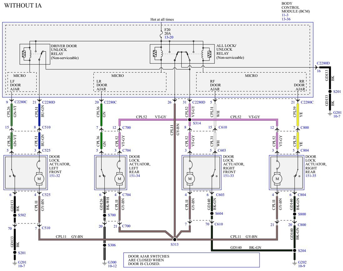
Welcome to the Forum @Strange locks! Since you are seeing lock plunger movement while the door remains locked, it's possible the door lock rod is binding or bent, or the door latch's power lock actuator has weakened. From the 2013 Edge Workshop Manual... Pinpoint Test B: A Single/More Than One Door Lock Is Inoperative Refer to Wiring Diagrams Cell 110 , Power Door Locks for schematic and connector information. Normal Operation The Body Control Module (BCM) supplies voltage to the lock all relay, the unlock driver door relay or unlock all relay based upon input from the door lock control switches, the Remote Keyless Entry (RKE) transmitter, or the keyless entry keypad. Upon a lock request, the BCM supplies voltage on the all door lock circuit and ground on the driver and passenger door unlock circuits. Upon an unlock request, the voltage and ground are reversed on the previously listed circuits. When the door lock and unlock relays are not energized they are connected to ground. A dedicated BCM ground circuit is provided only for the lock and unlock relays. This pinpoint test is intended to diagnose the following: Wiring, terminals or connectors Door lock actuator BCM PINPOINT TEST B : A SINGLE/MORE THAN ONE DOOR LOCK IS INOPERATIVE NOTICE: Use the correct probe adapter(s) when making measurements. Failure to use the correct probe adapter(s) may damage the connector. B1 CHECK THE DOOR LATCH FOR BINDING Lock and unlock the inoperative door lock using the door lock rod. Does the door lock and unlock? Yes GO to B3. No GO to B2. B2 CHECK THE LOCK ROD FOR BINDING Operate the door lock rod manually while observing the door lock rod for any binding or if the rod is bent. Is the door lock rod bent or binding? Yes REPAIR as necessary. TEST the system for normal operation. No INSTALL a new door latch. REFER to Front Door Latch or Rear Door Latch in this section. TEST the system for normal operation. B3 CHECK THE ALL LOCK OUTPUT CIRCUIT FOR VOLTAGE Ignition OFF. Disconnect: Inoperative Door Lock Actuator . NOTE: The BCM only supplies voltage to the actuator momentarily. It is important to monitor the meter while pressing the door lock control switch. While pressing the door lock control switch in the LOCK position, measure the voltage between the inoperative door lock actuator, harness side and ground as follows: Inoperative Door Lock Actuator Connector-Pin Circuit LH front C525 Pin 4 CPL11 (GY/BN) RH front C603 Pin 4 CPL11 (GY/BN) LH rear C704 Pin 4 CPL11 (GY/BN) RH rear C804 Pin 4 CPL11 (GY/BN) Is the voltage momentarily greater than 10 volts? Yes GO to B4. No REPAIR circuit CPL11 (GY/BN) for an open. TEST the system for normal operation. B4 CHECK THE UNLOCK OUTPUT CIRCUIT FOR VOLTAGE NOTE: The BCM only supplies voltage to the actuator momentarily. It is important to monitor the meter while pressing the door lock control switch. While pressing the door lock control switch in the UNLOCK position, measure the voltage between the inoperative door lock actuator, harness side and ground as follows: Inoperative Door Lock Actuator Connector-Pin Circuit LH front C525 Pin 3 CPL51 (BU/GN) RH front C603 Pin 3 CPL52 (VT/GY) LH rear C704 Pin 3 CPL52 (VT/GY) RH rear C804 Pin 3 CPL52 (VT/GY) Is the voltage momentarily greater than 10 volts? Yes INSTALL a new door latch. REFER to Front Door Latch or Rear Door Latch in this section. No GO to B5. B5 CHECK THE UNLOCK OUTPUT CIRCUIT FOR AN OPEN Disconnect: BCM C2280D . Measure the resistance between the BCM , harness side and the inoperative door lock actuator, harness side as follows: BCM Connector-Pin Inoperative Door Lock Actuator Connector-Pin Circuit C2280D Pin 21 LH front C525 Pin 3 CPL51 (BU/GN) C2280D Pin 31 RH front C603 Pin 3 CPL52 (VT/GY) C2280D Pin 31 LH rear C704 Pin 3 CPL52 (VT/GY) C2280D Pin 31 RH rear C804 Pin 3 CPL52 (VT/GY) Is the resistance less than 5 ohms? Yes GO to B6. No REPAIR the circuit for an open. TEST the system for normal operation. B6 CHECK FOR CORRECT BCM OPERATION Disconnect all the BCM connectors. Check for: corrosion damaged pins pushed-out pins Connect all the BCM connectors and make sure they seat correctly. Operate the system and verify the concern is still present. Is the concern still present? Yes INSTALL a new BCM . REFER to Section 419-10. TEST the system for normal operation. No The system is operating correctly at this time. The concern may have been caused by a loose or corroded connector. Additional Workshop Manual procedures are attached below as PDF documents... Good luck! Front Door Latch - Removal and Installation - 2013 Edge Workshop Manual.pdf Door Trim Panel — Front - Removal and Installation - 2013 Edge Workshop Manual.pdf


-
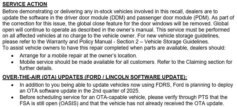
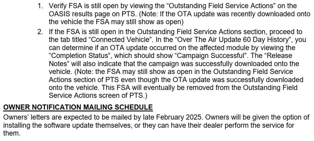
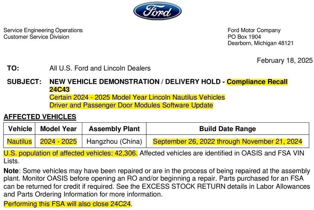
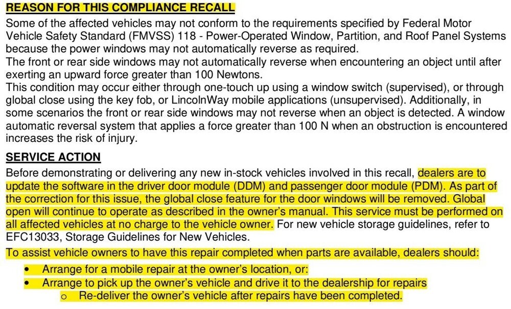
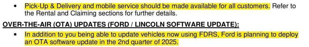
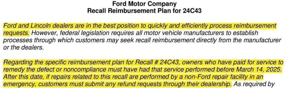
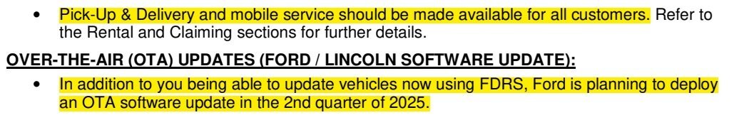
** The complete U.S. Dealer Bulletin has been released. The Canadian version will be posted when it is also released ** Compliance Recall 24C43's service procedure is described in the Technical Instructions attached below as a PDF document... Compliance Recall 24C43 - Technical Instructions.pdf

-
2024 Edge rattle noise from rear cargo trim panel
Haz replied to lasseventies's topic in 2.0L EcoBoost
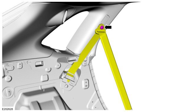
Welcome to the Forum @lasseventies! As your highlighted illustration and your comment indicates, the rear seatbelt retractor lies beneath the trim panel, and it contains a pyrotechnic (mildly explosive) device to pretension the belt in event of a crash. Because your Edge is under warranty and within its Low Time In Service (LTIS) period, during which repairs are extensively documented and reported back to Ford, you really should contact your dealer to have a professional technician diagnose and correct the noise's root cause, which may be directly related to the seatbelt retractor assembly. Good luck!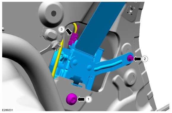
-
Welcome to the Forum @kelster! Related procedures from the 2022-2024 Edge Workshop Manual are attached below as PDF documents... Good luck! High Mounted Stoplamp - Removal and Installation - 2022-2024 Edge Workshop Manual.pdf Liftgate Trim Panel - Removal and Installation - 2022-2024 Edge Workshop Manual.pdf Rear Spoiler - Removal and Installation - 2022-2024 Edge Workshop Manual.pdf
-
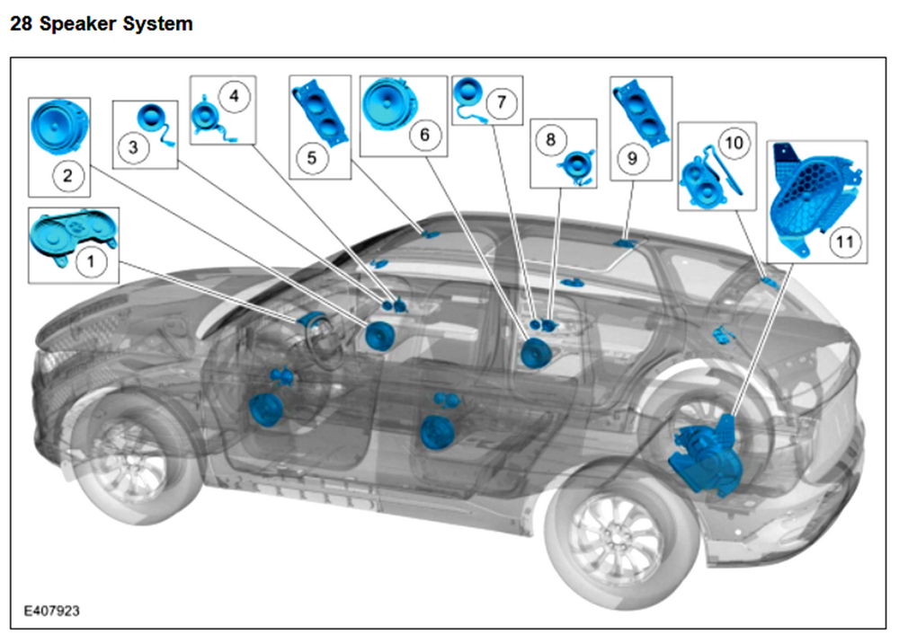
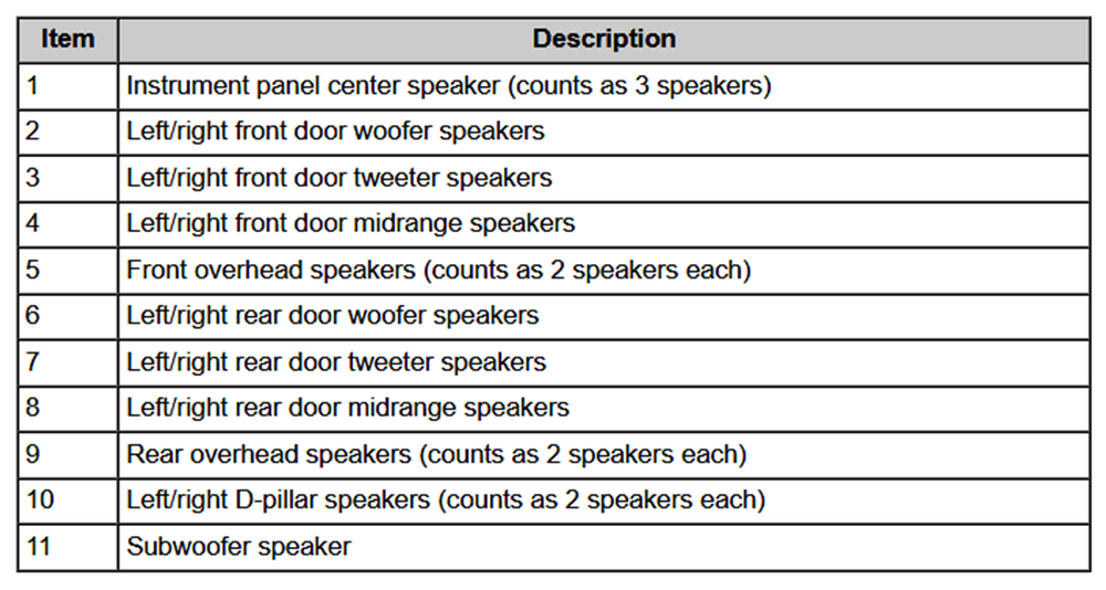
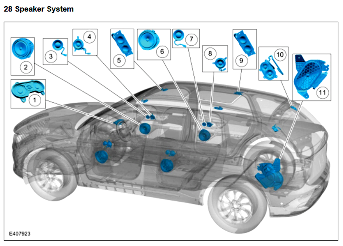
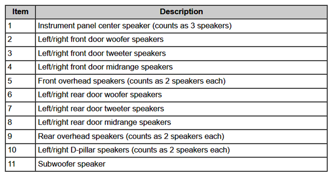
SSM 53377 2024 Nautilus, 2025 Aviator - No Audio/Sound - 24 Channel Audio Digital Signal Processing Module (DSP) (Minor Feature Code IDBBN) No Communication Some 2024 Nautilus and 2025 Aviator vehicles equipped with a 24 channel audio digital signal processing module (DSP) (minor feature code IDBBN) may exhibit a no audio/sound condition with no communication with DSP. To confirm a vehicle is built with a certain minor feature code, review the build information by double-clicking the vehicle identification number (VIN) in the upper left corner in the Professional Technician System (PTS). This concern may be due to software in the DSP. To determine if it is a software concern, remove the DSP fuse, F40 for Aviator or F138 for Nautilus, and inspect the fuse for an open and make sure the fuse has proper blade contact. After one minute, reinstall the good fuse. If the concern is still present or a fuse concern is found, continue with normal Workshop Manual diagnostics, Section 415-00 Information and Entertainment System > General Information > Diagnosis and Testing. If communication has been re-established with the DSP, reprogram the DSP using the latest software level of the Ford Diagnosis and Repair System (FDRS) scan tool. For claiming, use causal part 18B849 and applicable labor operations in Section 10 of the Service Labor Time Standards (SLTS) Manual. The involved audio system is the Revel Ultima 3D with 28-speakers, installed on 2024 Nautilus Reserve III 203A and 2024 Nautilus Black Label editions... Information and Entertainment System - Component Location Gratitude to @Bunky for the heads-up!
- 1 reply
-
- 3
-

-
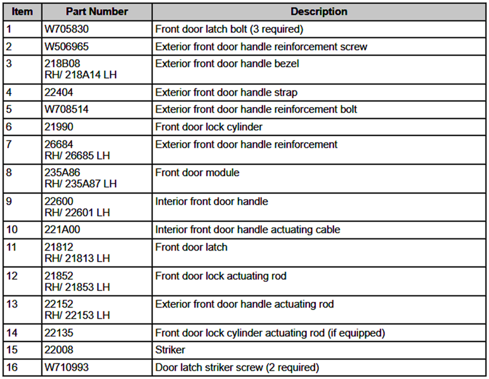
GENERAL SERVICE BULLETIN Tire Pressure Monitoring Systems (TPMS) Identification 25-7012 10 February 2025 This bulletin supersedes 23-7172. Reason for update: revised Table 1 (Figure 40) Summary This article supersedes GSB 23-7172 to update the vehicle model years affected and Service Information. This bulletin contains information on TPMS identification of Ford versus non-Ford sensors along with warrantable versus non-warrantable concerns and examples. Service Information Tires Overview Tires are designed to operate within a specific range of air pressures. The recommended inflation pressure is printed on the decal on the driver's door jamb (B-Pillar). The decal specifies the proper tire inflation. Tire pressure should be checked monthly as recommended in the Owner's Manual because all tires lose pressure over time. A tire's inflation pressure cannot be judged by appearance alone. By the time a low profile radial tire looks low, it may already be 10 to 15 PSI underinflated. The accuracy of some new inexpensive tire pressure gauges can be off by several PSI. Checking tire inflation pressure requires an accurate tire pressure gauge. TPMS Technology When the vehicle begins to move, a switch inside the sensor activates the pressure measurement and signal sending function. At about 20 mph (32 km/h), the sensor begins measuring the pressure every 30 seconds and transmits the results once each minute to the control module. The sensors transmit tire pressure data to the control module at 315 MHz or 433 MHz depending on the vehicle model year. Trailer TPMS and most export vehicles use 433 MHz. After inflating the tires to the recommended inflation pressure, the vehicle must be driven at 20 mph (32 km/h) or more for a few minutes for the light to turn off. Ford Original Equipment (OE) Sensor (Edison Housing) Markings And Part Details (Figures 1-2) Figure 1 Item Description 1 Sensor ID 2 Ford Part Number 3 Sensor Build Date (Year/Month/Day) Figure 2 Item Description 1 FoMoCo Label 2 Pressure Port 3 Do Not Discard Warning 4 FCC Identification and Frequency Ford OE Sensor (Potted Faraday) Markings And Part Details (Figures 3-4) Figure 3 Item Description 1 Sensor ID 2 Ford Part Number 3 Sensor Build Date (Year/Month/Day) Figure 4 Item Description 1 FoMoCo Label 2 Pressure Port 3 Do Not Discard Warning 4 FCC Identification and Frequency Ford OE Sensor (Faraday) Markings And Part Details (Figures 5-6) Figure 5 Item Description 1 FoMoCO Label 2 Sensor Frequency 3 Sensor Build Date (Year/Month/Day) 4 Pressure Port 5 Sensor ID 6 FCC Identification 7 Ford Part Number Figure 6 Item Description 1 Do Not Discard Warning 2 Visual Identifier (Part Specific) Ford OE Sensor (MHSSI) Markings And Part Details (Figures 7-8) Figure 7 Item Description 1 Sensor ID 2 Ford Part Number 3 Sensor Build Date (Year/Month/Day) 4 Visual Identifier (Part Specific) 5 Sensor Frequency 6 FCC Identification 7 FoMoCo Label 8 Pressure Port Figure 8 Item Description 1 Do Not Discard Warning Ford OE Sensor (Burnell) Markings And Part Details (Figure 9) Figure 9 Item Description 1 Sensor ID 2 Ford Part Number 3 Sensor Build Date (Year/Month/Day) 4 Visual Identifier (Part Specific) 5 Sensor Frequency 6 FCC Identification 7 FoMoCo Label 8 Pressure Port 9 Do Not Discard Warning Ford OE Sensor (Steel Carcass) Markings And Part Details (Figures 10-11) Figure 10 Item Description 1 Sensor ID 2 FoMoCo Label 3 Pressure Port 4 Visual Identifier (Part Specific) 5 FCC Identification 6 Sensor Frequency Figure 11 Item Description 1 Ford Part Number 2 Sensor Build Date (Year/Month/Day) 3 Do Not Discard Warning Ford OE Sensor (Trailer) Markings And Part Details (Figures 12-13) Figure 12 Item Description 1 Ford Part Number 2 Sensor Build Date (Year/Month/Day) 3 Sensor ID 4 Sensor Frequency 5 FoMoCo Label 6 FCC Identification Figure 13 Item Description 1 Pressure Port 2 Do Not Discard Warning Ford OE Sensor (Trailer Steel Carcass) Markings And Part Details (Figures 14-15) Figure 14 Item Description 1 Sensor ID 2 FoMoCo Label 3 Sensor Frequency 4 FCC Identification 5 Pressure Port Figure 15 Item Description 1 Ford Part Number 2 Sensor Build Date (Year/Month/Day) 3 Do Not Discard Warning Ford OE Sensor (Edison/Faraday) Components (Figures 16-17) NOTE: When replacing the valve, make sure to replace the valve only, not the entire sensor kit. Otherwise, this is an over-repair and not warrantable. Figure 16 Item Description 1 Cap 2 Valve Stem 3 Valve Air Port 4 Bolt Figure 17 Item Description 1 Cap 2 Valve Stem 3 Valve Air Port 4 Bolt Ford OE Sensor (Bolt-On Faraday) Components (Figure 18) NOTE: When replacing the valve, make sure to replace the valve only, not the entire sensor kit. Otherwise, this is an over-repair and not warrantable. Figure 18 Item Description 1 Cap 2 Hex Nut 3 Bolt 4 Washer 5 Valve Air Port 6 Valve Stem Ford OE Sensor (MHSSI) Components (Figure 19) NOTE: When replacing the valve, make sure to replace the valve only, not the entire sensor kit. Otherwise, this is an over-repair and not warrantable. Figure 19 Item Description 1 Cap 2 Valve Stem 3 Valve Air Port 4 Bolt Ford OE Sensor (Burnell) Components (Figure 20) NOTE: When replacing the valve, make sure to replace the valve only, not the entire sensor kit. Otherwise, this is an over-repair and not warrantable. Figure 20 Item Description 1 Cap 2 Valve Stem 3 Valve Air Port 4 Bolt Ford OE Sensor (Steel Carcass - Straight) Components (Figure 21) NOTE: When replacing the valve, make sure to replace the valve only, not the entire sensor kit. Otherwise, this is an over-repair and not warrantable. Figure 21 Item Description 1 Washer 2 Hex Nut 3 Cap 4 Valve Stem 5 Bolt 6 Valve Air Port (flows through bolt) Ford OE Sensor (Steel Carcass - Bent) Components (Figure 22) NOTE: When replacing the valve, make sure to replace the valve only, not the entire sensor kit. Otherwise, this is an over-repair and not warrantable. Figure 22 Item Description 1 Cap 2 Washer 3 Hex Nut 4 Valve Stem 5 Bolt 6 Valve Air Port (flows through bolt) Ford OE Sensor (Trailer) Components (Figure 23) NOTE: When replacing the valve, make sure to replace the valve only, not the entire sensor kit. Otherwise, this is an over-repair and not warrantable. Figure 23 Item Description 1 Cap 2 Valve Stem 3 Valve Air Port 4 Hex Nut 5 Washer Ford OE Sensor (Trailer Steel Carcass) Components (Figure 24) NOTE: When replacing the valve, make sure to replace the valve only, not the entire sensor kit. Otherwise, this is an over-repair and not warrantable. Figure 24 Item Description 1 Cap 2 Valve Stem 3 Washer 4 Hex Nut 5 Bolt 6 Valve Air Port (flows through bolt) Identifying Correct Ford OE Sensor (DE8T / Edison) For A Particular Vehicle (Figure 25) Figure 25 1 - DE8T-1A180-** Engineering Part Number Description DE8T-1A180-** 315 MHz Edison Identifying Correct Ford OE Sensor (GL3T / Faraday) For A Particular Vehicle (Figure 26) Figure 26 2 - GL3T-1A180-** Engineering Part Number Description GL3T-1A180-AA 315 MHz Faraday GL3T-1A180-CA 433 MHz Faraday Identifying Correct Ford OE Sensor (GL3T / Potted Faraday) For A Particular Vehicle (Figure 27) Figure 27 2 - GL3T-1A180-** Engineering Part Number Description GL3T-1A180-GA 315 MHz Faraday - High Speed Valve GL3T-1A180-GB 315 MHz Faraday - High Speed Valve GL3T-1A180-HA 433 MHz Faraday GL3T-1A180-HB 433 MHz Faraday Identifying Correct Ford OE Sensor (ML3T / Potted Faraday) For A Particular Vehicle (Figures 28-29) Figure 28 Figure 29 3 - ML3T-1A180-** Engineering Part Number Description ML3T-1A180-AA 315 MHz Potted Faraday ML3T-1A180-CA 433 MHz Potted Faraday (Grey Enclosure) Identifying Correct Ford OE Sensor (F2GT / Faraday) For A Particular Vehicle (Figure 30) Figure 30 4 - F2GT-1A180-** Engineering Part Number Description F2GT-1A180-AA 315 MHz Faraday - Low Speed Valve F2GT-1A180-AB 315 MHz Faraday - Low Speed Valve F2GT-1A180-AC 315 MHz Faraday - Low Speed Valve F2GT-1A180-AD 315 MHz Faraday - Low Speed Valve F2GT-1A180-AE 315 MHz Faraday - Low Speed Valve F2GT-1A180-EA 433 MHz Faraday - Low Speed Valve F2GT-1A180-EB 433 MHz Faraday - Low Speed Valve Identifying Correct Ford OE Sensor (HC3T / Faraday) For A Particular Vehicle (Figure 31) Figure 31 5 - HC3T-1A180-** Engineering Part Number Description HC3T-1A180-AA 315 MHz Faraday - High Speed Valve HC3T-1A180-AB 315 MHz Faraday - High Speed Valve HC3T-1A180-AC 315 MHz Faraday - High Speed Valve HC3T-1A180-AD 315 MHz Faraday - High Speed Valve HC3T-1A180-AE 315 MHz Faraday - High Speed Valve HC3T-1A180-GA 315 MHz Faraday - High Speed Valve HC3T-1A180-GB 315 MHz Faraday - High Speed Valve Identifying Correct Ford OE Sensor (FR3V / Bolt-On Faraday) For A Particular Vehicle (Figure 32) Figure 32 6 - FR3V-1A180-** Engineering Part Number Description FR3V-1A180-AA 315 MHz Faraday - Bolt-On Valve FR3V-1A180-AB 315 MHz Faraday - Bolt-On Valve FR3V-1A180-AC 315 MHz Faraday - Bolt-On Valve FR3V-1A180-CC 433 MHz Faraday - Bolt-On Valve FR3V-1A180-GB 315 MHz Faraday - Bolt-On Valve E-Coated Washer FR3V-1A180-HB 433 MHz Faraday - Bolt-On Valve E-Coated Washer Identifying Correct Ford OE Sensor (JX7T / MHSSI) For A Particular Vehicle (Figure 33) Figure 33 7 - JX7T-1A180-** Engineering Part Number Description JX7T-1A180-AA 315 MHz MHSSI - High Speed Valve JX7T-1A180-EA 315 MHz MHSSI - Low Speed Valve Identifying Correct Ford OE Sensor (PR3T / Burnell) For A Particular Vehicle (Figure 34) Figure 34 8 - PR3T-1A180-** Engineering Part Number Description PR3T-1A180-AB 315 MHz Burnell - Low Speed Valve PR3T-1A180-CB 433 MHz Burnell - High Speed Valve PR3T-1A180-EB 315 MHz Burnell - Bolt-On Valve PR3T-1A180-GB 433 MHz Burnell - Bolt-On Valve PR3T-1A180-KB 433 MHz Burnell - Low Speed Valve #2 PR3T-1A180-MB 433 MHz Burnell - Low Speed Valve Identifying Correct Ford OE Sensor (PC3T / Steel Carcass) For A Particular Vehicle (Figures 35-36) Figure 35 Figure 36 9 - PC3T-1A180-** Engineering Part Number Description PC3T-1A180-CA 433 MHz Steel Carcass Production Steel Wheel Valve (Bent Brass) PC3T-1A180-GB 433 MHz Steel Carcass Production Alloy Wheel Valve Identifying Correct Ford OE Sensor For Trailer TPMS (Figure 37) Figure 37 10 - HC3T-1A180-** Engineering Part Number Description HC3T-1A180-CA 433 MHz Trailer Sensor HC3T-1A180-CB 433 MHz Trailer Sensor HC3T-1A180-CC 433 MHz Trailer Sensor Identifying Correct Ford OE Sensor For Steel Carcass Trailer TPMS (Figures 38-39) Figure 38 Figure 39 11 - PC3T-1A180-** Engineering Part Number Description PC3T-1A180-JB 433 MHz Trailer Steel Carcass Sensor TPMS Identification Chart (Figure 40) The numbers in this chart identify the type of sensors for each vehicle program. The numbers are in the upper left corner of the tables in Figures 25-39. Figure 40 - TPMS Identification Chart Model 2015 2016 2017 2018 2019 2020 2021 2022 2023 2024 2025 Aviator 7 7 7 8 8 Bronco 3 3 3 3 8 Bronco Sport 4 4 4 4 8 Continental 4 4 4 4 4 C-Max 1 1 Corsair 7 7 7 7 7 7 EcoSport 4 4 4 4 Edge 4 4 5 5 2, 5 2, 4 3, 4 3, 4 3, 4 3, 4 Escape 1 1 1 1 1 7 7 7 7 7 7 E-Series 1 1 1 1 1 2, 6 2, 6 2, 3 2, 3 2, 3 8 Expedition 1 1 1 2, 5 2, 5 2 2 2, 3 3 3 8 Explorer / Police Interceptor Utility 1 4 4 4 4 7 7 7 7 8 8 F-150 4 2 2 2 2 2 3 3 3 3 3 F-150 Lightning 3 3 3 3 3 F-150 Raptor 2 2 2 2 2 3 3 3 3 3 F-Super Duty 1 1 5, 6 2, 5, 6 2, 5, 6 2, 5, 6 2, 6 2, 3, 6 3, 6 3, 6 6, 8 Fiesta 1 1 1 4 4 4 Flex 1 1 1 1 1 Focus 1 1 1 1 Ford GT * * * * * * Fusion 1 1 5 5 5 5 Maverick 4 4 4 4 8 MKC 1 1 1 5 5 MKS 1 1 MKT 1 1 1 1 1 MKX 4 4 2, 4 2, 4 MKZ 1 1 5 5 5 5 Mustang 4 4 4 4 4 4 4 4 4 4 8 Mustang Mach-E 4 4 4 8 Mustang SVT ** 6 6 6 6 6 6 6 6 6 6 Nautilus 2, 5 2, 4 3, 4 3, 4 3, 4 3, 4 3, 4 Navigator 1 1 1 2, 5 2, 5 2 2 2, 3 3 3 8 Ranger 5 5 3 3 3 3 8 Taurus / Police Interceptor Sedan 1 1 1 1 1 Transit 1 1 1 1 1 6, 7 6, 7 6, 7 6, 7 6, 7 6, 8 Transit Connect 1 1 1 4 4 4 4 4 4 8 Trailer TPMS Kit 10 10 10 10 10 10 10, 11 11 11 Figure 40 legend * Ford GT uses a specialized black anodized bolt-on valve. The part number prefix for this is HG7Z. ** Mustang SVT uses a bolt-on valve. The part number prefix for this is DR3V. TPMS Sensor Non-Warrantable Issues With the variety of sensors that come equipped on Ford/Lincoln vehicles, make sure the sensor type is carefully identified and the correct mount and dismount procedure is used for each type of TPMS sensor. Damage to the TPMS sensor is identifiable with each part being reviewed prior to warranty approval. The sensor may not respond for a number of non-warrantable reasons that require the replacement of the sensor. They are: • Damage due to improper tire mount and/or dismount procedure • Damage due to being run on a flat or severely under-inflated tire • Damage due to impact • Damage due to improper removal of the valve stem • Sensor replaced due to the use of a tire sealant • Pressure port clogged due to the use of sealants or other materials (rubber, grease, balancing materials, etc.) • Damage due to mounting on wheels not designed to accommodate TPMS sensors properly Other Non-Warrantable Conditions: • Wrong frequency parts • Wrong sensor type (both Ford and non-Ford sensors) • Over-repair (replacing the whole sensor vs replacing a valve) Good Part Examples (Figures 41-44) Figure 41 Item Description 1 Undamaged valve stem 2 Undamaged ladder area/lid 3 Undamaged sensor body Figure 42 Item Description 1 Correct Ford Part Number 2 Undamaged Sensor Body Figure 43 Item Description 1 Pressure Port Not Obstructed 2 Undamaged Valve Stem Figure 44 Item Description 1 Undamaged Valve Stem 2 Undamaged Potting Non-Ford Part Examples (Chargebacks) Different colors. North American units all use black parts. (Figures 45-46) Figure 45 Figure 46 No Ford part number (Figures 47-48) Figure 47 Figure 48 Different shapes. NOTE: North American units all use either the Edison or the Faraday profile. (Figure 49) Figure 49 Aftermarket Branding. NOTE: This could include branding such as EzSensor, Redi, and Schrader (Figure 50) Figure 50 Sensor Damage Examples (Chargebacks) Damaged valve stems (Figures 51-54) Figure 51 Figure 52 Figure 53 Figure 54 Damage to the sensor body (Figures 55-56) Figure 55 Figure 56 Avoiding Chargebacks Wrong Part Details: Things To Look For: 1. Does the sensor build date make sense for the model year of the vehicle? For example, if the sensor was built in 2019, it would not make sense to see this on a vehicle that is newer than the date on the sensor. It should be fairly close to the vehicle's production date. 2. Does the part number match what is listed in the catalog? 3. Is the part the correct frequency? Unless it is a trailer sensor the frequency for North American vehicles should be 315 MHz. Wrong Part Returned: This is the most common chargeback when it comes to TPMS. A few ways to avoid being charged back for this can include: 1. Include the sensor ID, build date, and part number within the technician comments. This will make sure that the part attached to the 700 tag is the part that is returned. 2. Verify the correct sensor using the parts catalog or this document. Sending back an Edison sensor instead of a Faraday sensor will result in a chargeback and vice versa. 3. Include a second copy of the 700 tag in the shipping box/envelope if attaching to the outside package. 4. Do not return a sensor that was made in 2009 for a vehicle that was made in 2019, as an example. If the sensor is over a year old compared to the vehicle build date then it is highly likely it is the wrong part. 5. Do not send back non-Ford TPMS sensors or other Ford parts. 6. Do not send back 433 MHz sensors if the vehicle has over 1,000 miles. North American vehicles do not use this frequency (trailer TPMS does). Sensor Damaged: This is the second most common chargeback: 1. The easiest way to avoid being charged back for this is to properly dismount the tire. Also making sure to remove the sensor from the valve stem before attempting to remove the valve stem. 2. If a sensor is damaged, and it is not caused by the plant, then do not send it back. Plant damage is easily determined upon review. 3. Do not send back a sensor if the valve stem was damaged. 4. Any defacing or intentional damaging of the part will result in a chargeback. Over Repair: This is the third most common chargeback. Examples of this include: 1. Replacing the entire sensor kit for a leaky valve. Order the proper valve kit to replace the valve. 2. Replacing the entire sensor kit for a cracked or blemished wheel. 3. Replacing all 4 sensors due to a BCM or RTM issue. 4. Replacement BCMs do not have the TPMS IDs stored in them. Non-functional RTMs will cause TPMS faults. © 2025 Ford Motor Company All rights reserved. NOTE: This information is not intended to replace or supersede any warranty, parts and service policy, workshop manual (WSM) procedures or technical training or wiring diagram information.
- 1 reply
-
- 3
-
-
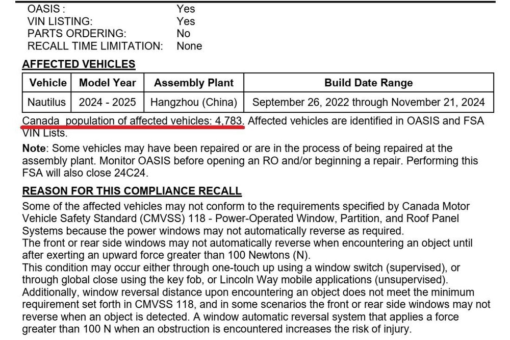
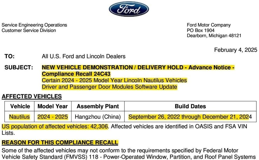
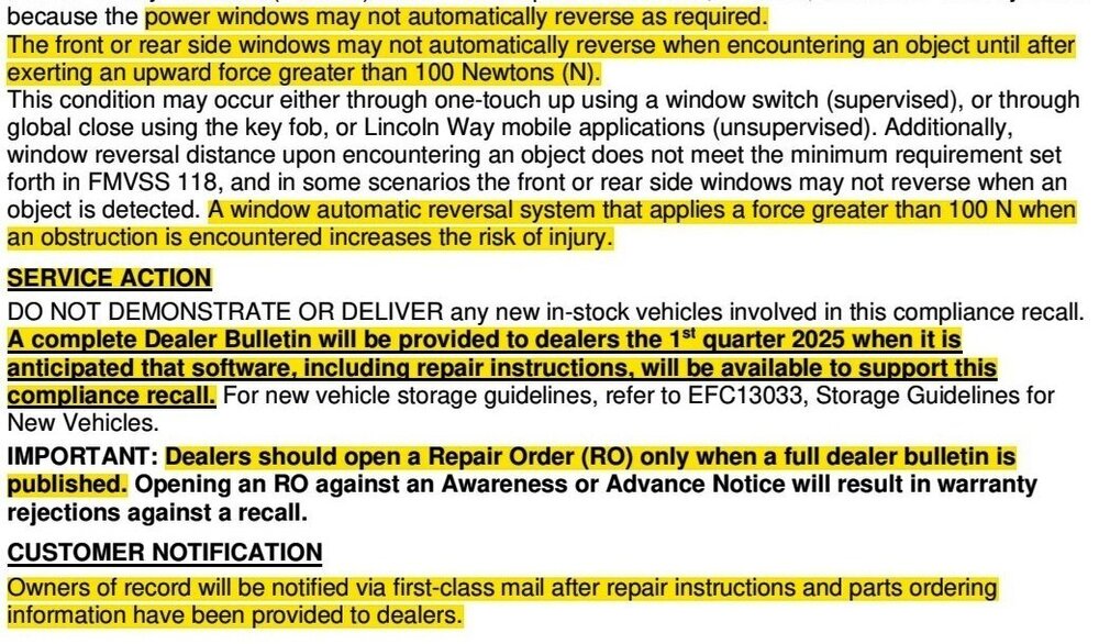
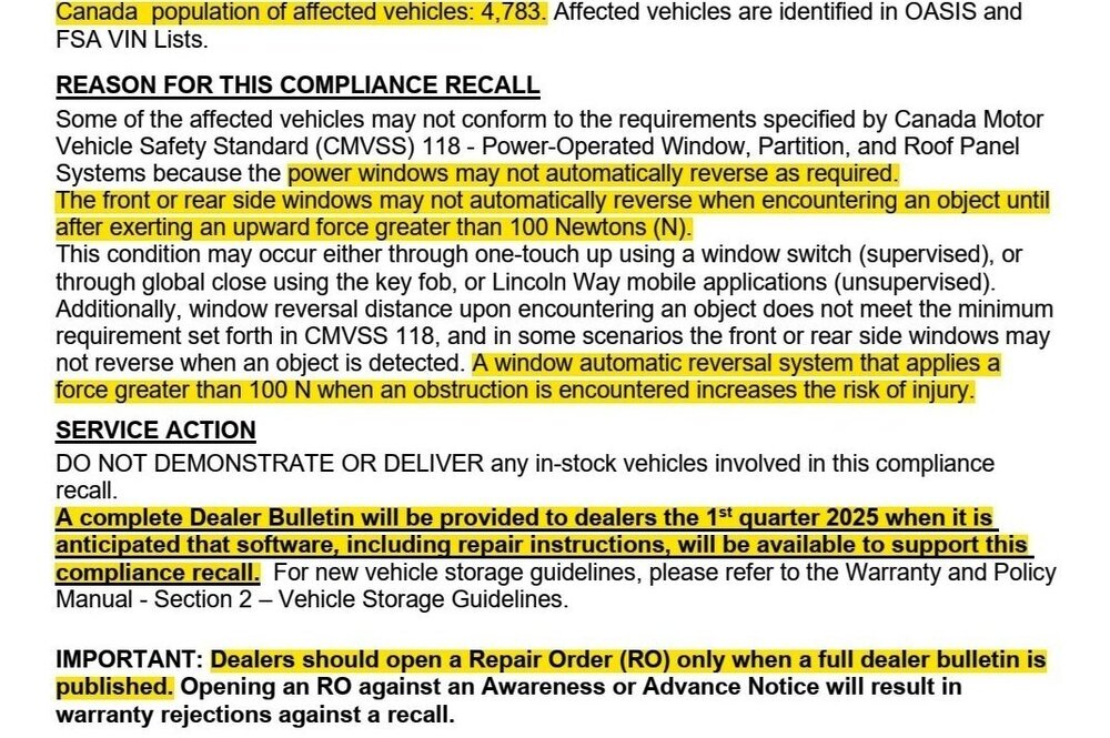
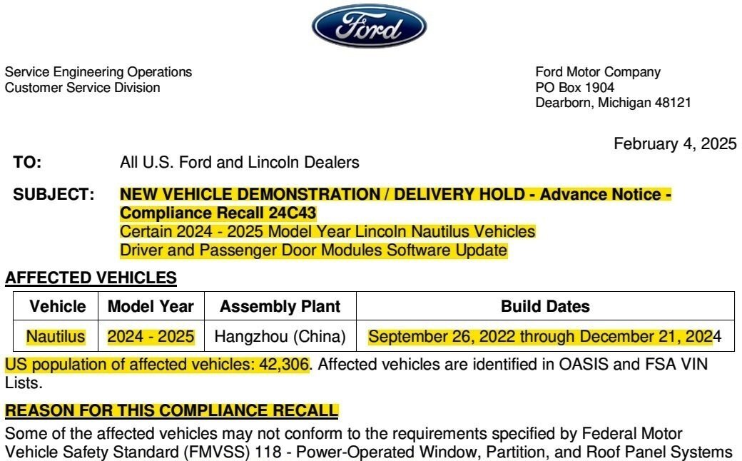
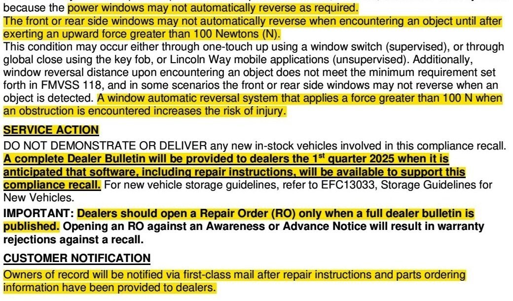
Compliance Recall 24C24 has been amended by Compliance Recall 24C43, which expands the Build Dates of affected units to include certain 2025 Nautilus vehicles. For more information, please see... Compliance Recall 24C43 - Advance Notice to Dealers - Certain 2024-2025 Nautilus - Driver and Passenger Door Modules Software Update - USA & Canada
-
**This is an Advance Notice - The Full Dealer Bulletin has been released and is posted immediately below**

-
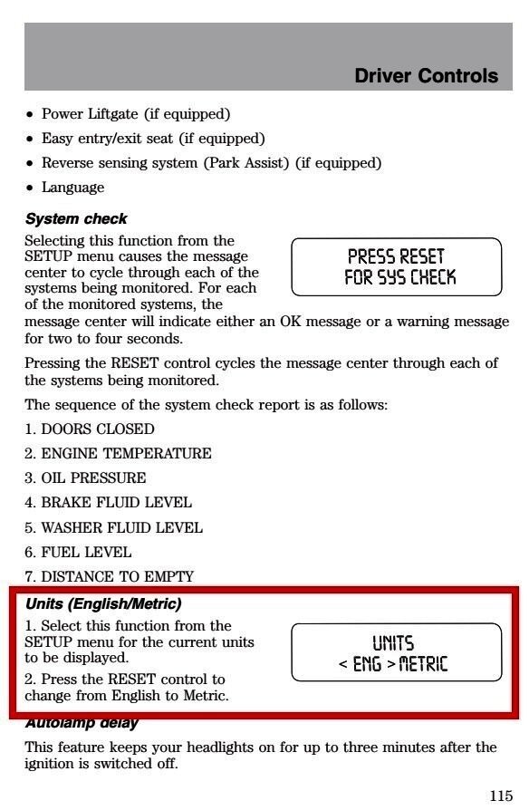
2008 Edge Limited - Changing dash display from metric to imperial
Haz replied to RobynL_328's topic in 2008 Edge & MKX
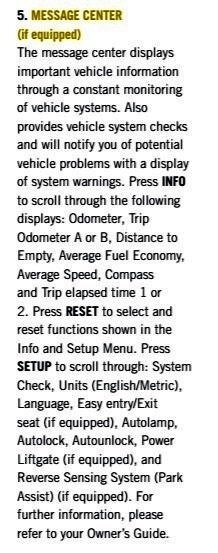
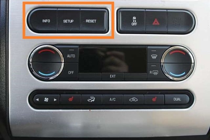
Recapping with photos: 2008 Edge Limited Instrument Cluster with Message Center digital screen... 2008 Edge Limited Instrument Panel Center Stack with Message Center control buttons, orange-boxed in this photo... Message Center Instructions on use of "Info" - "Setup" - "Reset" control buttons shown in the above photo... These instructions are contained in the 2008 Edge Quick Reference Guide, which is attached below as a PDF document... Good luck! 2008 Edge Quick Reference Guide 1st Ed.pdf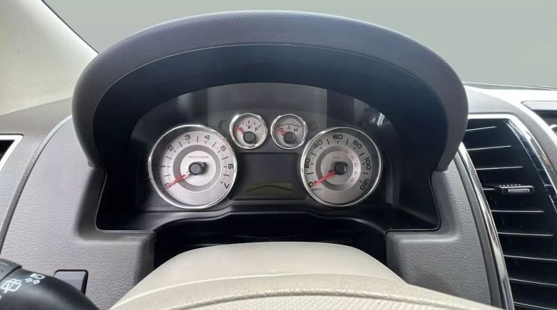
-
Welcome to the Forum, @chasityalaniz5! Your description of vehicle symptoms suggests the Park Detect Switch in the Edge's transmission shifter may need to be replaced, per the following Technical Service Bulletin 17-2219, with emphasis added... TECHNICAL SERVICE BULLETIN Push Button Start-Shift To Park Or Transmission Not in Park Message-Discharged Battery/Unable To Remove Key 17-2219 14 December 2017 This bulletin supersedes 15-0047. Reason for update: New Part/Procedure For Same Condition Model: Ford 2011-2017 Edge 2011-2017 Explorer 2011-2017 Flex 2011-2017 Police Interceptor - Sedan 2011-2017 Taurus Lincoln 2011-2016 MKS 2011-2017 MKT 2011-2015 MKX Summary The article supersedes TSB 15-0047 to direct all repairs to the updated service procedures now available through the online Workshop Manual. Issue: Some 2011-2015 MKX, 2011-2016 MKS, and 2011-2017 Edge/Explorer/MKT/Flex/Taurus built with a floor shift selector lever and push button start models may exhibit a Shift To Park message, Transmission Not In Park message displayed while the shifter is in park position, or unable to remove the integrated keyhead transmitter (IKT), or a discharged battery due to the Shift to Park light remaining illuminated. Action: Follow the Service Procedure steps to correct the condition. Parts Service Part Number Package Order Quantity Description GT4Z-3F988-B 1 Shifter Kit – Park Detect Switch, 2011-2014 Edge/2011-2015 MKX/Explorer G2GZ-3F988-B 1 Shifter Kit – Park Detect Switch, 2015-2017 Edge GA8Z-3F988-B 1 Shifter Kit – Park Detect Switch, 2011-2017 Flex GG1Z-3F988-B 1 Shifter Kit – Park Detect Switch, 2011-2017 Taurus GE9Z-3F988-B 1 Shifter Kit – Park Detect Switch, 2011-2016 MKS/2011-2017 MKT GB5Z-3F988-B 1 Shifter Kit – Park Detect Switch, 2016-2017 Explorer Warranty Status: Information Only. Service Procedure Refer to the updated service procedures located in the online Workshop Manual (WSM), Section 307-05 to service the park detect switch on push button start vehicles or shifter assembly on key start vehicles and Powertrain Control/Emission Diagnosis (PC/ED) manual. The Park Detect Switch is located in beneath the blue-highlighted protective cover highlighted in this illustration... Technical Service Bulletin 17-2219, and the Park Detect Switch replacement procedure from the 2014 Edge Workshop Manual, are attached below as PDF documents. Good luck! TSB 17-2219 - Push Button Start-Shift To Park Or Transmission Not in Park Message.pdf Park Detect Switch — Vehicles with push button ignition - Removal and Installation - 2014 Edge Workshop Manual.pdf

-
Insert for compartment located on console
Haz replied to Keith1341's topic in 2019-Current Edge & Nautilius
@Edgingage: Discussion on the components you mention can be found here... Good luck! -
2008 Edge Limited - Changing dash display from metric to imperial
Haz replied to RobynL_328's topic in 2008 Edge & MKX
From the 2008 Edge Owner's Guide, page 115... ersion Just in case your 2008 Edge is missing an Owner's Guide in its glove box, a PDF document version of the full Owner's Guide is attached below. Good luck! 2008 Ford Edge Owner Guide 1st Ed.pdf
-
2012 Edge Radio Battery Saver-Instrument Cluster Black
Haz replied to openrage's topic in Audio, Backup, Navigation & SYNC
Welcome to the Forum @openrage! From the 2012 Edge Workshop Manual... The Body Control Module (BCM) uses the battery current sensor to monitor the battery state of charge. The battery current sensor is attached to the battery ground cable. With the ignition in RUN, ACC, or OFF, a Load Shed message is sent over the CAN when the BCM determines that the battery state of charge is below 40%, 45 minutes have elapsed, or 10% of the charge has been drained. This message turns off the audio system to save the remaining battery charge. Under this condition, SYS OFF TO SAVE BATT is displayed on the center stack infotainment display to notify the driver that battery protection actions are active. To clear the Load Shed state, start the vehicle. Often, as you describe, when symptoms develop across several electronic systems, the root cause is low battery voltage, causing electronic modules to not operate properly and causing Diagnostic Trouble Codes (DTCs) to be set in them. Using a Diagnostic Scan Tool to check for DTCs can be useful toward understanding what's affecting your Edge. The stuck climate controls may be the result of a DTC that, when cleared, will restore the climate control function. You mention you have replaced the vehicle's weak battery and that the Load Shed state and messaging persists, which suggests the replacement battery also has a state of charge issue. If your replacement battery is not newly purchased -- or even if it is -- have the battery load-tested to ensure it isn't faulty or failing due to bad internal cells. For the inoperative Instrument Panel Cluster (IPC), check fuse F11 (10 amp) in the BCM... Normal Operation The Instrument Panel Cluster (IPC) receives a hot at all times voltage from the Body Control Module (BCM) fuse 11 (10A). The IPC uses a run/start input messaged from the BCM over the High Speed Controller Area Network (HS-CAN) . Please let us know the outcome of your further efforts. Good luck! Instrument Panel Cluster (IPC) - Power Distribution Wiring Diagram - 2012 Edge.pdf Body Control Module (BCM) - Fuse & Connector Locations - 2012 Edge.pdf Body Control Module (BCM) - Fuse Panel Location - 2012 Edge.pdf-Red-CircledBCMFuseF11-WiringDiagram-2012Edge.thumb.jpg.fe2fd7eb57a9a911c7b32e996ab3f5c1.jpg)
-Red-BoxedFuseF11(10amp)Location-2012Edge.thumb.jpg.8bd7ea07581e402c7c3d1a79570aefc1.jpg)
-Red-BoxedFusePanelLocation-2012Edge.thumb.jpg.90a537bd5c25f481cc0c48cdb82a97c8.jpg)
-
From the 2021 Edge Workshop Manual, attached below as PDF documents... Good luck! Accessory Protocol Interface Module (APIM) - Removal and Installation - 2021 Edge Workshop Manual.pdf Center Display Screen - Removal and Installation - 2021 Edge Workshop Manual.pdf
-
From the 2011 Edge Workshop Manual, with emphasis added... Illuminated Entry The illuminated entry requests the dimmable backlighting, the parking lamps and the courtesy lamps to illuminate when the ignition is off and a door or liftgate is opened, the RKE transmitter UNLOCK button is pressed, or the vehicle is unlocked using the keyless entry keypad. If no doors are open, the illuminated entry requests the lamps off after 25 seconds have elapsed, the ignition switched out of off, the RKE transmitter LOCK button is pressed, or the vehicle is locked using the keyless entry keypad. Illuminated Exit The illuminated exit requests the dimmable backlighting, the parking lamps, and the courtesy lamps to illuminate for 25 seconds after all doors are closed and the ignition is turned off. The illuminated exit deactivates when the ignition transitions out of off, a door or liftgate becomes ajar, or 25 seconds have elapsed. Ambient Lighting The ambient lighting subsystem provides illumination to the center console cupholders, the storage bin, the door map pockets, the door pull handles, the door release handles, and the front and rear footwells for illuminated entry or when the ignition is in run with the parking lamps on. The ambient lighting is controlled using the touch screen display in the center of the instrument panel. When the illuminated entry feature is active, the ambient lighting defaults to a pre-set color and brightness setting. When all the doors are closed and the illuminated entry is no longer active, the ambient lighting returns to the last color and brightness setting that was set by the operator. The touch screen display is used to select one of 7 color combinations or turn the ambient lighting feature on or off. The ambient lighting system retains the last color setting and brightness between uses. For vehicles with memory seats, the ambient lighting color can also be set to correspond to the Driver 1 or Driver 2 settings. Good luck!


-HeaterPwr-GndSuppliedViaRainSensorConectorC914Pins13-WiringDiagram-2019Edge.jpg.c7278596d2902a1149baa5882aafdf68.jpg)


-Red-CircledBCMFuseF11-WiringDiagram-2012Edge.jpg.464e90aedb3acb738103817c5cff4a94.jpg)
-Red-BoxedFuseF11(10amp)Location-2012Edge.jpg.7f33e0069fbdad24a54430e2dc052af2.jpg)
-Red-BoxedFusePanelLocation-2012Edge.jpg.05b1dc37b73b4cf983fc74fd6fccf191.jpg)