Haz
-
Posts
1,460 -
Joined
-
Last visited
-
Days Won
392
Content Type
Profiles
Forums
Gallery
Everything posted by Haz
-
Thickest double-sided I've found is 3M 4959, 1/8" thick, in various widths... Document download links> 3M™ VHB™ Tape - Specialty Tape 4959F Technical Data Sheet.pdf 3M VHB Family of Specialty Tapes - Technical Data Sheet.pdf Good luck!
FoamMountingTape-McMaster-Carr.thumb.jpg.84f146046275bc97c3e9913e281cfdb9.jpg)
-
check engine Check Engine Light w/ABS or Traction Ctrl
Haz replied to Sunnyorlando's topic in Brakes, Chassis & Suspension
Pending feedback on specific Diagnostic Trouble Codes (DTCs), per the 2017 Edge Workshop Manual... The Anti-Lock Brake System (ABS) module originates and The Powertrain Control Module (PCM) originates Relating to the Instrument Panel Cluster (IPC)... Networked Input Messages and Default States NOTE: Whenever a network message is suspected as missing and confirmed by a missing message DTC (U-code), it is important to look for other symptoms that can also be present in the IPC and throughout the vehicle. Once a DTC sets in the IPC , it is helpful to review the complete message list to determine which other modules also rely on the same message and run the self-test for those modules. If the message is missing from other modules, the same or similar lost communication DTC can also be set in those modules. Confirmation of missing messages common to multiple modules can indicate the originating module is the source of the concern or the communication network may be faulted. Network messages can drop out or be missing for a variety of reasons, such as high network traffic on the bus. The IPC incorporates a defined strategy for handling missing network messages based on time. The required time for a network message to be missing differs between the various gauges, indicators and message center displays. The strategy is basically the same for all indication outputs (gauges, indicators or chimes), but differs in the length of time required for the network message to be missing. If a required network message is missing or invalid for less than the programmed length of time, the gauge, indicator or message center display that requires the network message remains at the last commanded state based upon the last network message received. If the messaged input is missing for longer than the programmed length of time, the IPC output (gauge, indicator etc.) reacts according to a pre-defined default action. For example, if the stability-traction control indicator request network message is missing for less than 5 seconds, and the stability-traction control indicator (sliding car icon) was on, the indicator remains in the on state until the next network message is received. If the network message remains missing or invalid for more than 5 seconds, the IPC sets a U-code DTC and the IPC output becomes a default action for the indicator or gauge. The indicator may default on/off or the gauge may default to the rest position. The PCM setting the MIL indicator immediately after an ABS/Traction Control event could be the result of missing Communications Network messages and, given the combination of events, possibly... DTC Fault Trigger Condition-PCM DTC Description Fault Trigger Conditions U0121 Lost Communication With Anti-Lock Brake System (ABS) Control Module The PCM sets this DTC if data messages from the ABS module through the GWM are missing. Possible Sources Communications network concern ABS module BCM PCM PINPOINT TEST A: U0121 A1 VERIFY THE CUSTOMER CONCERN Ignition ON. Verify there is an observable symptom present. Is an observable symptom present? Yes GO to A2 No The system is operating normally at this time. The DTC may have been set due to high network traffic or an intermittent fault condition. A2 CHECK THE COMMUNICATION NETWORK Using a diagnostic scan tool, perform a network test. Did the ABS module pass the network test? Yes GO to A3 No REFER to: Communications Network (418-00 Module Communications Network, Diagnosis and Testing). A3 PERFORM ABS (ANTI-LOCK BRAKE SYSTEM) CONTROL MODULE SELF-TEST Using a diagnostic scan tool, perform a ABS control module self-test. Are any Diagnostic Trouble Codes (DTCs) recorded? Yes REFER to: Anti-Lock Brake System (ABS) and Stability Control (206-09 Anti-Lock Brake System (ABS) and Stability Control, Diagnosis and Testing). No GO to A4 A4 CHECK THE BCM (BODY CONTROL MODULE) DIAGNOSTIC TROUBLE CODES (DTCS) Using a diagnostic scan tool, retrieve the BCM Diagnostic Trouble Codes (DTCs). Are any Diagnostic Trouble Codes (DTCs) recorded? Yes REFER to: Body Control Module (BCM) (419-10 Multifunction Electronic Modules, Diagnosis and Testing). No GO to A5 A5 PERFORM THE PCM (POWERTRAIN CONTROL MODULE) SELF-TEST Using a diagnostic scan tool, perform the PCM self-test. Is DTC P0562 or DTC P0563 recorded? Yes REFER to PCM DTC Chart in this section. No GO to A6 A6 RECHECK THE PCM (POWERTRAIN CONTROL MODULE) DIAGNOSTIC TROUBLE CODES (DTCS) NOTE: If new modules were installed prior to the DTC being set, the module configuration may be incorrectly set during the PMI , or the PMI may not have been carried out. Using a diagnostic scan tool, clear the Diagnostic Trouble Codes (DTCs). Wait 10 seconds. Repeat the PCM self-test. Is DTC U0121 still present? Yes GO to A7 No The system is operating correctly at this time. The DTC may have been set due to high network traffic or an intermittent fault condition. A7 CHECK FOR DTC (DIAGNOSTIC TROUBLE CODE) U0121 SET IN OTHER MODULES Using a diagnostic scan tool, clear all Diagnostic Trouble Codes (DTCs). Ignition OFF. Ignition ON. Wait 10 seconds. Using a diagnostic scan tool, retrieve all Continuous Memory Diagnostic Trouble Codes (CMDTCs) from all modules. Is DTC U0121:00 set in any other module? Yes GO to A8 No GO to A9 A8 CHECK FOR CORRECT ABS (ANTI-LOCK BRAKE SYSTEM) MODULE OPERATION Ignition OFF. Disconnect and inspect all ABS control module connectors. Repair: corrosion (install new connector or terminals – clean module pins) damaged or bent pins – install new terminals/pins pushed-out pins – install new pins as necessary Reconnect all the ABS control module connectors. Make sure they seat and latch correctly. Operate the system and determine if the concern is still present. Is the concern still present? Yes CHECK OASIS for any applicable Technical Service Bulletins (TSBs). If a TSB exists for this concern, DISCONTINUE this test and FOLLOW TSB instructions. If no Technical Service Bulletins (TSBs) address this concern, INSTALL a new ABS module. REFER to: Anti-Lock Brake System (ABS) Module (206-09 Anti-Lock Brake System (ABS) and Stability Control, Removal and Installation). No The system is operating correctly at this time. The concern may have been caused by module connections. ADDRESS the root cause of any connector or pin issues. Of course, feedback of a non-"U" DTC reduces all of this information to a learning opportunity, and then, appropriate DTC-based guidance from the Workshop Manual will be shared. Good luck!

-2017EdgeWorkshopManual.thumb.jpg.486892915d60ad458f8933abc4f2ed1a.jpg)
-
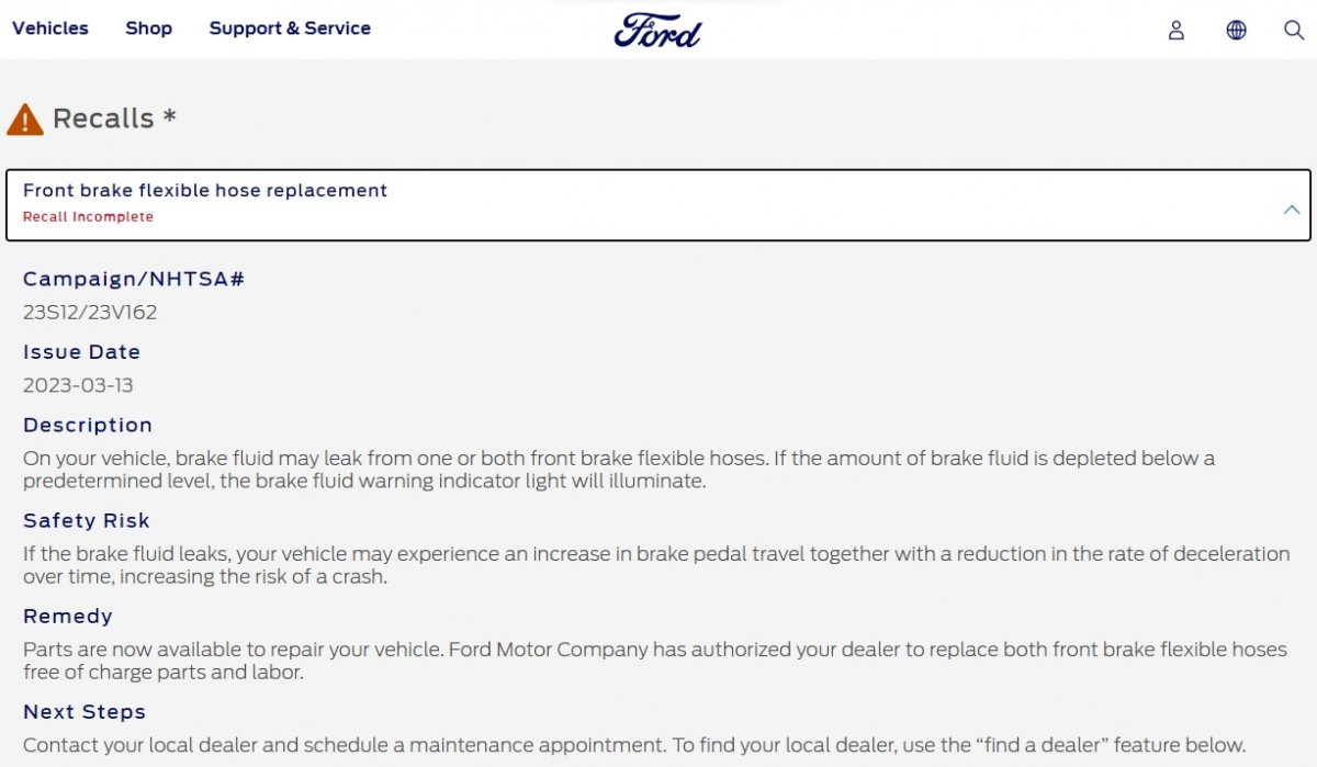
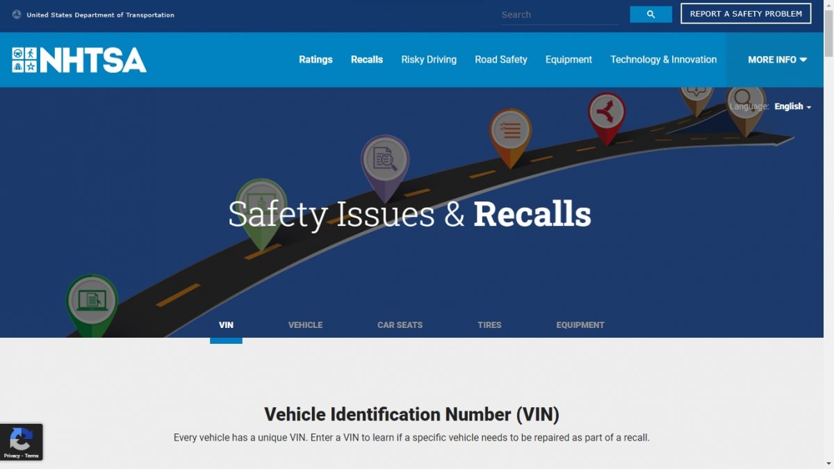
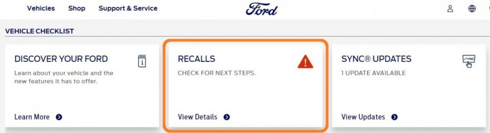
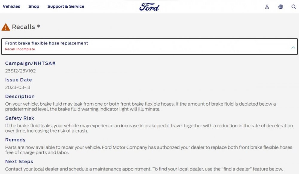
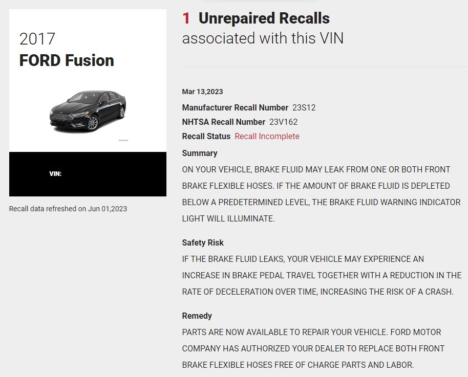
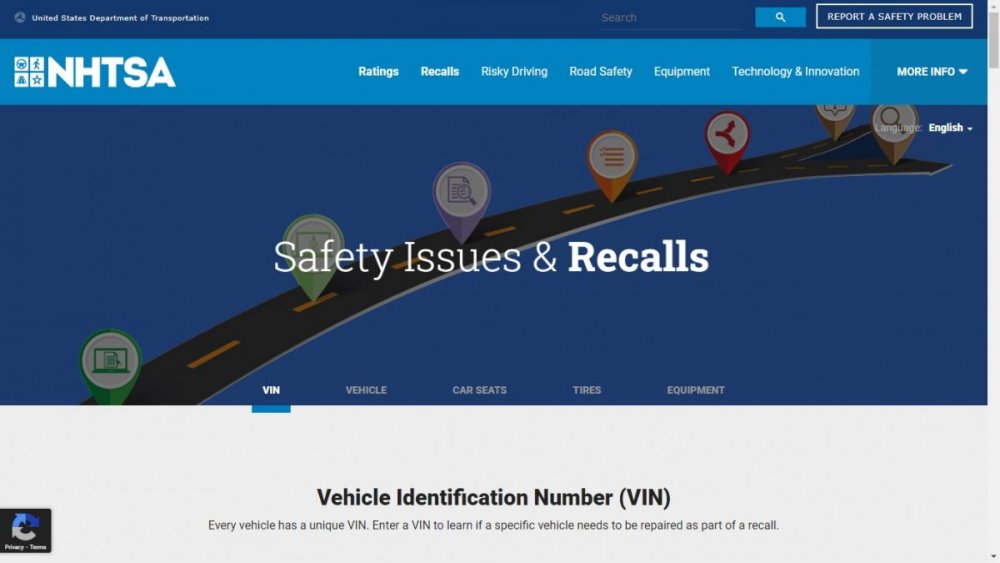
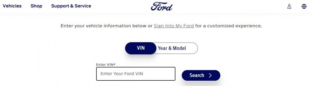
Adding visuals to support Chipster's advice, using an eligible Fusion VIN... VIN Search Page Support Dashboard Page... Recall Detail Page... Similarly, the NHTSA site provides Recall Status via VIN Search... NHTSA VIN Search Results... And finally, the dealer enters the VIN into OASIS to determine Field Service Action eligibility... It's worth noting that in OASIS and on the Ford Support site, eligibility previously shown for Customer Satisfaction Program 22N02 has been removed, and eligibility for Safety Recall 23S12 has been added. Good luck!

-
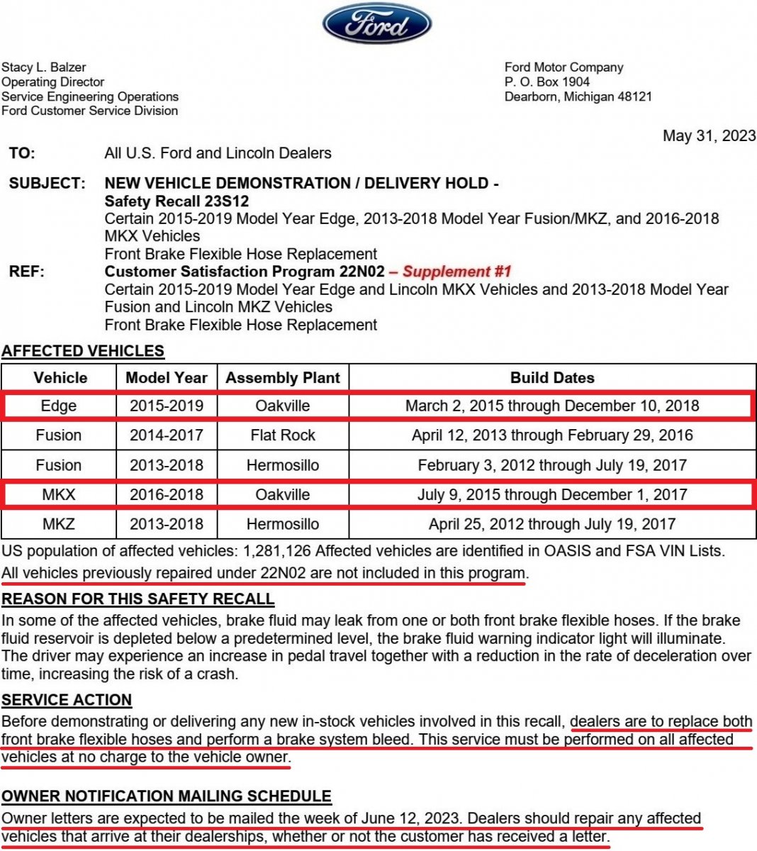
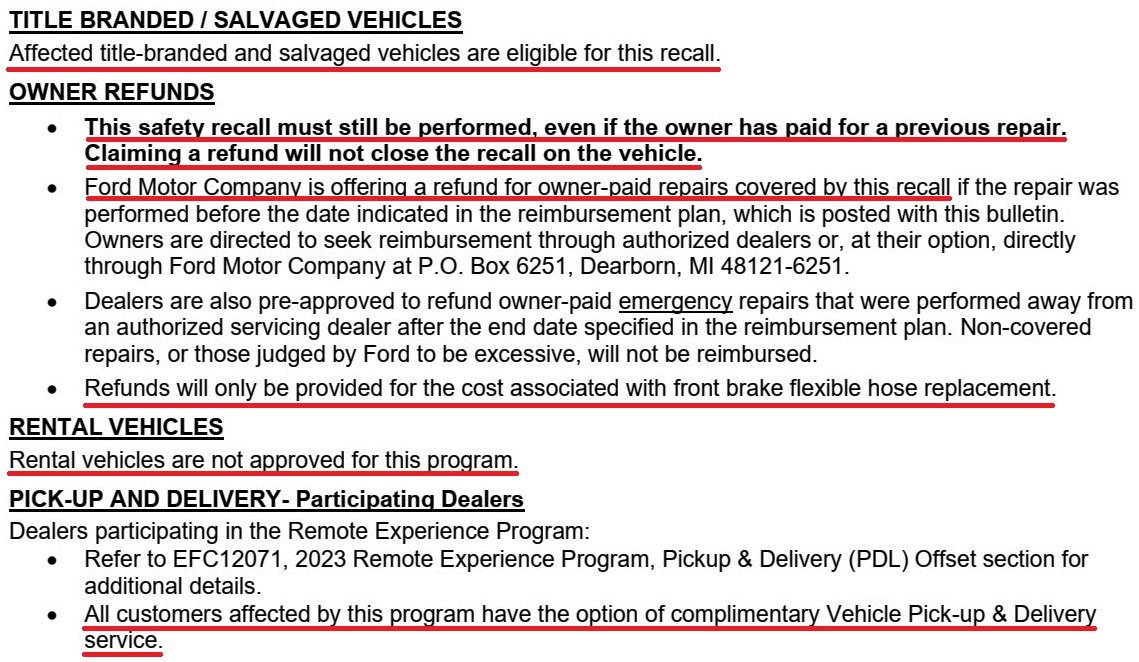
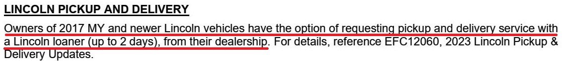
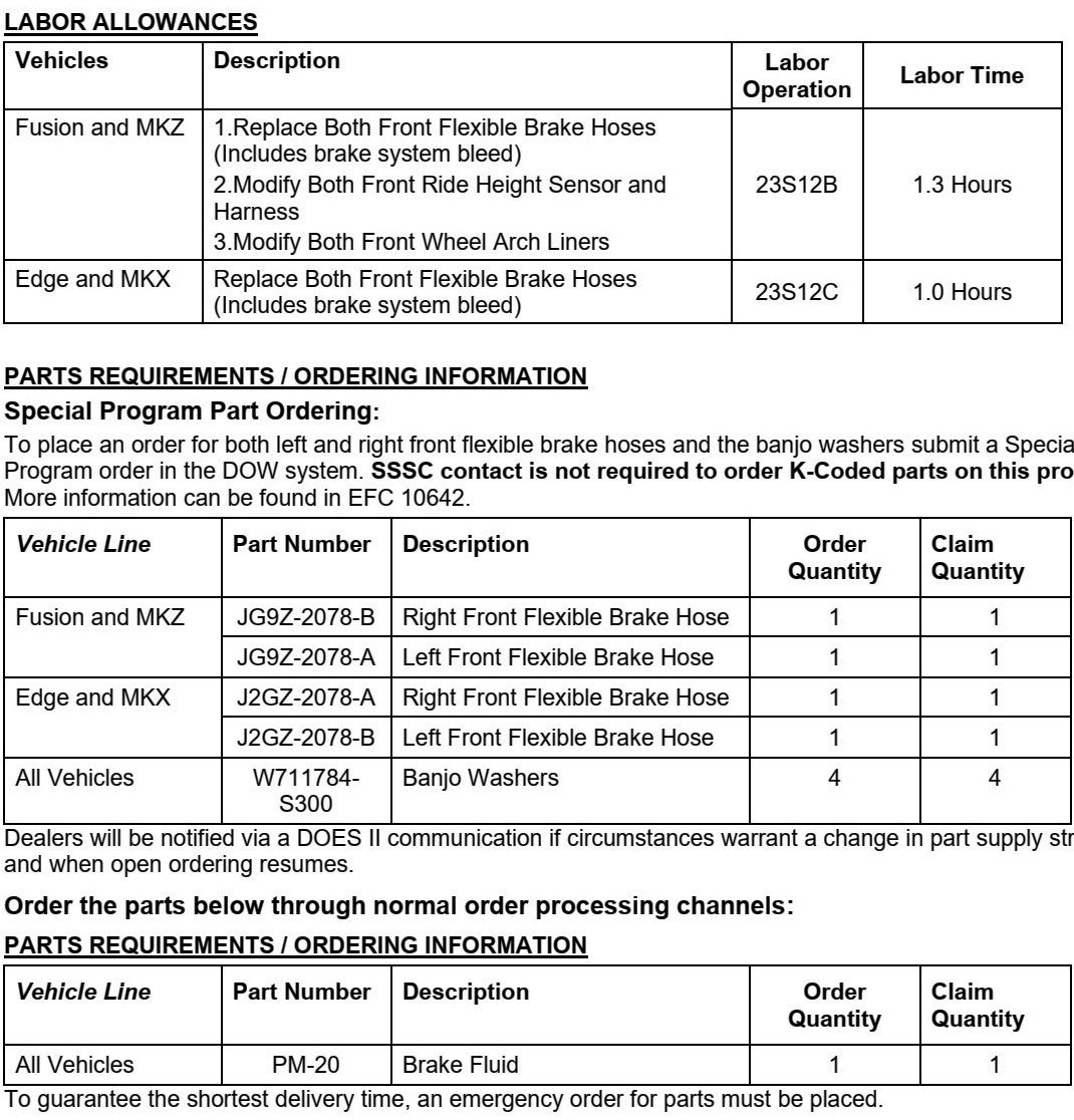
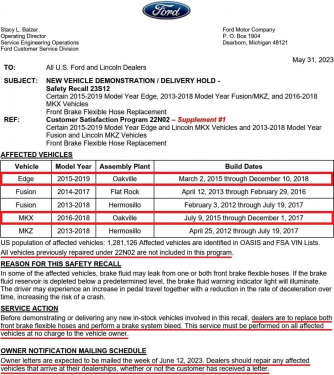
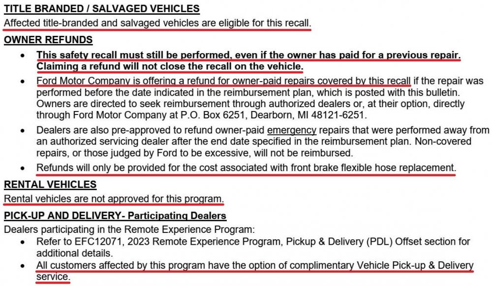
The complete Notice To Dealers letter has been released, along with Service Procedure details. Owner letters to be mailed week of June 12, 2023... Document download link> Safety Recall 23S12 - Front Flexible Brake Hose Replacement - Technical Info.pdf Good luck!

-
2007 edge se cluster swap to mkx cluster
Haz replied to rdm21740's topic in Accessories & Modifications
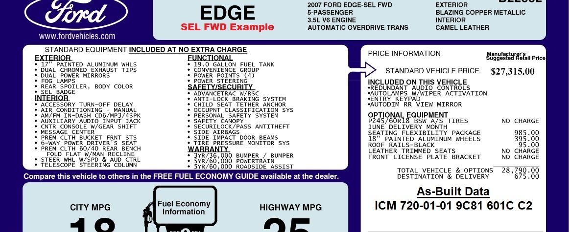
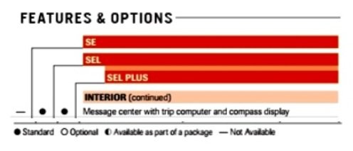
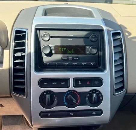
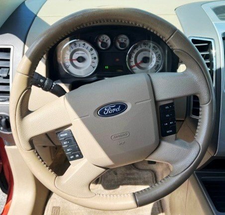
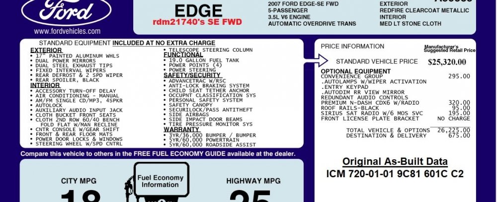
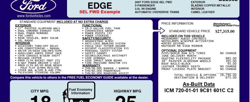
A survey of Edge sales brochures reveals that your silver-faced Message Center Instrument Cluster was installed as standard equipment in 2007-2010 Edge SELs... It's useful that you're aware the Message Center instrument cluster came from an AWD vehicle because that explains the Diagnostic Trouble Codes (DTCs) involving the Transfer Case and secondary Fuel Sensor, which are not installed on your Edge SE FWD. Similarly, the other DTCs proceed from the Message Center Instrument Cluster presently containing As-Built programming values from the AWD vehicle, directing it to communicate with other modules or features which your Edge SE FWD lacks. Using the VIN you Forum-messaged me, I pulled the Window Sticker (cropped here to eliminate VIN info) to review your Edge's options, and I also obtained the As-Built data for your Edge's originally installed Instrument Cluster... Your Edge being equipped with the Convenience Group containing the Auto-Dimming Rear View Mirror is fortunate, because that interior mirror contains the Compass Module needed for the Message Center to display compass values. The lack of U2013 DTC indicates your Edge's Compass Module is communicating with the Message Center, despite the many DTCs generated by the AWD vehicle's As-Built data in Message Center Instrument Cluster. Knowing your Edge's equipment from its Window Sticker, and that the Message Center Instrument Cluster was standard equipment in 2007-2010 Edge SELs, I surveyed comparably equipped 2007 Edge SELs offered for sale online, which yielded this vehicle... The SEL FWD vehicle's online photos confirm it is equipped with the Message Center Instrument Cluster and the same Electronic Manual Temperature Control (EMTC) as your Edge, explaining their identical As-Built data, ICM 720-01-01 9C81 601C C2... a All of this causes me to expect that, if you use Forscan to write your Edge's original Instrument Cluster As-Built data to the Message Center Instrument Cluster, use Forscan to clear all DTCs and to perform Self-Test routines on the PCM and ICM to verify no DTCs reoccur, then the Wrench light and the plethora of DTCs should be gone, and the Message Center and Climate controls should be functional. Good luck!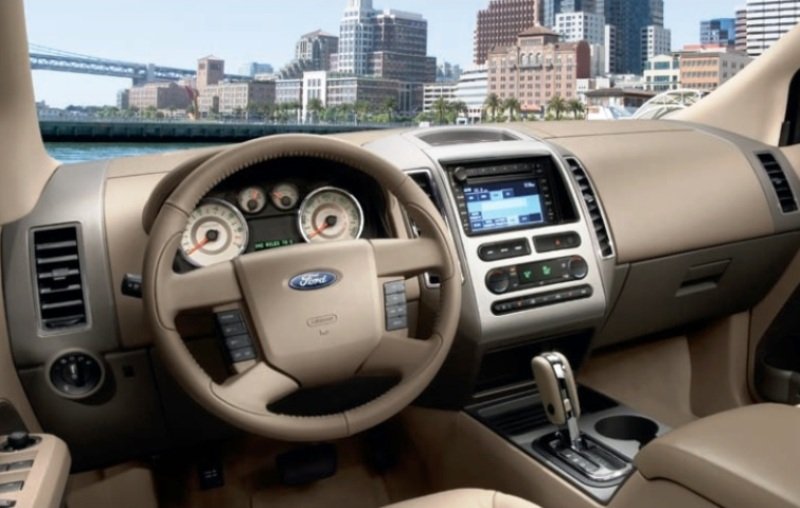
- 2 replies
-
- 3
-

-
- instrument
- cluster swap
- (and 1 more)
-
SSM 51665 - 2021-2023 Various Vehicles - 2.7L/3.0L Engines - Upper Engine Thump/Knock Noise Some 2021-2023 Ford and Lincoln vehicles equipped with a 2.7L or 3.0L engine may exhibit an upper engine thump/knock noise coming from the left cylinder head. This condition is most noticeable at idle and may lessen at higher engine speed or while driving. This condition does not affect vehicle durability and will not get worse over time. Use a stethoscope or chassis ears and listen just behind the left cylinder head intake VCT solenoid on the cam cover to determine if the thump/knock noise is coming from the cylinder head/camshaft. The left cylinder head and the camshaft roller followers are available as service parts.
-
From the 2019 Workshop Manual... The LH - RH Turn Signal Or High Beam Indicator Is Never or Always On Normal Operation and Fault Conditions See LH - RH Turn Signal Indicator or High Beam Indicator Indicator. REFER to: Instrument Panel Cluster (IPC) - System Operation and Component Description (413-01 Instrumentation, Message Center and Warning Chimes, Description and Operation). If the turn indication data or high beam status message is missing for less than 5 seconds, the IPC defaults the turn signal or high beam indicator to its last indication state (on or off), based upon the last message received. If the turn indication data or high beam status message is missing for 5 seconds or longer, the IPC defaults the turn signal or high beam indicator off. Possible Sources Turn signal concern High beam concern Communication concern BCM concern GWM concern IPC PINPOINT TEST S: THE LH (LEFT-HAND) - RH (RIGHT-HAND) TURN SIGNAL OR HIGH BEAM INDICATOR IS NEVER OR ALWAYS ON S1 DETERMINE THE FAULT CONDITION Ignition ON. Check the operation of the high beams or turn signals. Do the high beams or turn signals operate correctly? Yes GO to S2 No For high beams, REFER to: Headlamps (417-01 Exterior Lighting, Diagnosis and Testing). For turn signals, REFER to: Turn Signal and Hazard Lamps (417-01 Exterior Lighting, Diagnosis and Testing). S2 CHECK THE GWM (GATEWAY MODULE A) DIAGNOSTIC TROUBLE CODES (DTCS) Using a diagnostic scan tool, check the GWM Continuous Memory Diagnostic Trouble Codes (DTCs). Are any Diagnostic Trouble Codes (DTCs) recorded? Yes REFER to: Communications Network (418-00 Module Communications Network, Diagnosis and Testing). No GO to S3 S3 PERFORM THE IPC (INSTRUMENT PANEL CLUSTER) SELF-TEST Using a diagnostic scan tool, perform the IPC self-test. Are any Diagnostic Trouble Codes (DTCs) recorded? Yes REFER to DTC Chart: IPC in this section. No For the LH or RH turn indicator, GO to S4 For the high beam indicator, GO to S5 S4 CHECK THE LH (LEFT-HAND) AND RH (RIGHT-HAND) TURN INDICATOR OPERATION USING A DIAGNOSTIC SCAN TOOL Using a diagnostic scan tool, view the IPC Parameter Identifications (PIDs). Select the IPC RH or LH turn signal indicator (RH_TURN_L) or (LH_TURN_L) PID . Command the RH or LH turn signal indicator on and off while observing the RH or LH turn signal indicator. Does the RH or LH turn signal indicator illuminate when commanded on and turn off when commanded off? Yes DIAGNOSE all BCM Diagnostic Trouble Codes (DTCs). REFER to: Body Control Module (BCM) (419-10 Multifunction Electronic Modules, Diagnosis and Testing). No Click here to access Guided Routine (IPC). S5 CHECK THE HIGH BEAM INDICATOR OPERATION USING A DIAGNOSTIC SCAN TOOL Using a diagnostic scan tool, view the IPC Parameter Identifications (PIDs). Select the IPC high beam indicator (HIGH_BEAM) PID . Command the high beam indicator on and off while observing the high beam indicator. Does the high beam indicator illuminate when commanded on and turn off when commanded off? Yes DIAGNOSE all BCM Diagnostic Trouble Codes (DTCs). REFER to: Body Control Module (BCM) (419-10 Multifunction Electronic Modules, Diagnosis and Testing). No Click here to access Guided Routine (IPC). Guided Routine (IPC) download link> Pinpoint Test A - IPC Hardware Test - 2019 Edge Workshop Manual.pdf Additional document download link> Instrument Panel Cluster (IPC) - System Operation and Component Description - 2019 Edge Workshop Manual.pdf Let me know if you need any Diagnostic Trouble Code (DTC) diagnostics. Good luck!
- 1 reply
-
- 1
-
-
Document download links> Fuel Charging and Controls - Component Location - 3.5L Duratec - 2015 Edge Workshop Manual.pdf Fuel Rail and Injectors - Removal and Installation - 3.5L Duratec - 2015 Edge Workshop Manual.pdf Throttle Body - Removal and Installation - 3.5L Duratec - 2015 Edge Workshop Manual.pdf Good luck!
-
I have provided, via the Forum messaging system, instructions and a download link to documents which are too large to share here, due to file attachment limitations. Good luck!
-
Heater Hose Locations, instructions, diagrams and videos
Haz replied to TobyJ66's topic in 2.0L EcoBoost
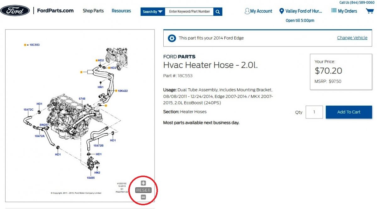
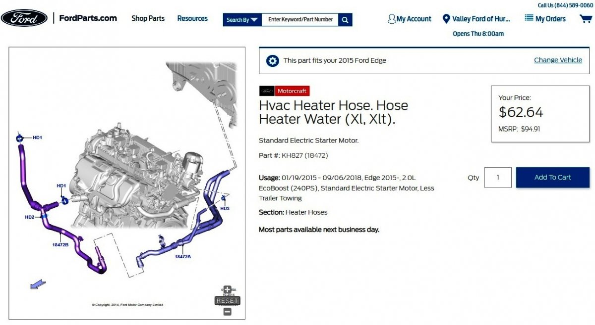
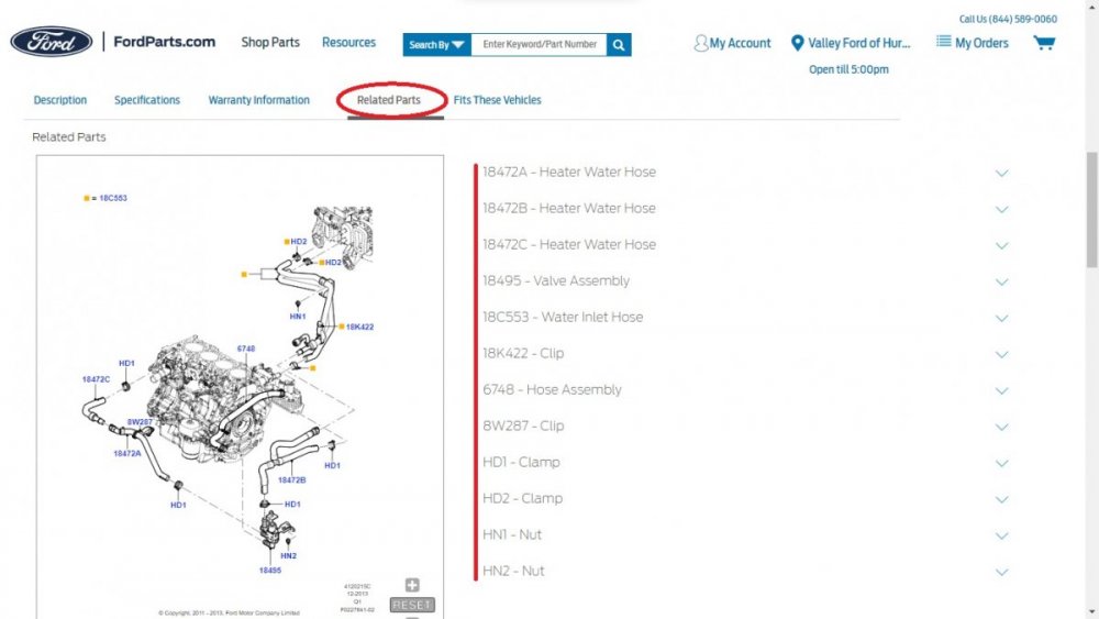
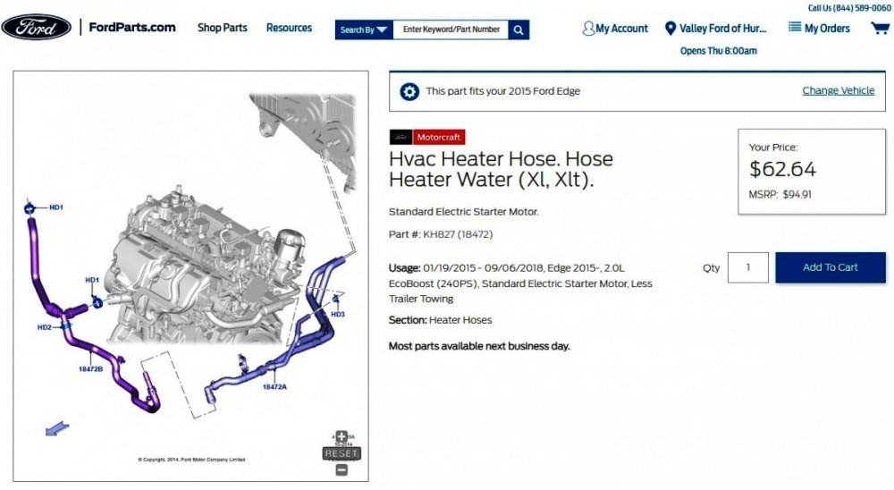
Welcome to the Forum, TobyJ66 ! Surprisingly, 2012-to-2023 Edge Workshop Manuals do not provide any procedure for removal and installation of heater hoses on the 2.0L EcoBoost, though differences do exist between Gen1+ (2012-2014) and Gen2 (2015-2023) 2.0L EcoBoost heater hose designs. Ford's online parts-selling site provides exploded illustrations which can be zoomed and dragged about to view the various hoses, as well as photos of individual hoses from several perspectives. Link to this FordParts.com webpage (Zoom control is red-circled) Scrolling down the page and selecting "Related Parts" yields links to individual parts shown in the illustration... Heater hose design differences are evident on the 2015 Edge 2.0L EcoBoost heater hose page, which also includes a "Related Parts" tab... Link to this FordParts.com webpage When beginning a FordParts part search, the site will ask for a zip code or city to build a list of nearby dealers to choose from. You'll notice that the dealer I selected above sells at below MSRP pricing. Not all dealers discount pricing, so you can choose among other dealers on your list to price-shop. The following 2014 Edge Workshop Manual sections may address your other question... Document download links> Radiator, 2.0L EcoBoost - Removal and Installation - 2014 Edge Workshop Manual.pdf Charge Air Cooler (CAC), 2.0L EcoBoost - Removal and Installation - 2014 Edge Workshop Manual.pdf Cooling Fan Motor and Shroud, 2.0L EcoBoost - Removal and Installation - 2014 Edge Workshop Manual.pdf Cooling System Draining, Filling and Bleeding - General Procedures - 2014 Edge Workshop Manual.pdf Bumper Cover, Front - Removal and Installation - 2014 Edge Workshop Manual.pdf Intake Manifold, 2.0L EcoBoost - Removal and Installation - 2014 Edge Workshop Manual.pdf Good luck!
-
Sorry, no first-hand experience nor Workshop Manual advice beyond the previously shared documents. EMT6996 is the subject matter expert here, I'd say. Good luck!
-
SSM 51656 - 2022-2023 F-150/Bronco/Expedition/Navigator/Escape/Corsair/Bronco Sport/Edge/Mustang MIL With DTC P0230 – Built On 04-Sep-2022 And Through 30-Dec-2022 Some 2022-2023 F-150/Bronco/Expedition/Navigator/Escape/Corsair/Bronco Sport/Edge/Mustang vehicles built on 04-Sep-2022 and through 30-Dec-2022 may exhibit an illuminated malfunction indicator lamp (MIL) with diagnostic trouble codes (DTC) P0230 stored in the powertrain control module (PCM). The vehicle may also experience a no start or stall after start. This may be due to an internal PCM issue. If this DTC is present, verify the battery condition, then perform pin point test (PPT) KC of the Work Shop Manual (WSM), Section 310-01. If PPT KC leads to component replacement, start with replacing the PCM and then evaluate the vehicle. If the DTC returns, follow WSM, Section 310-01 PPT KC direction to address the issue.
-
PremiumCARE ESP, Heated Steering Wheel Covered?
Haz replied to Odrapnew's topic in Recalls, TSBs & Warranty
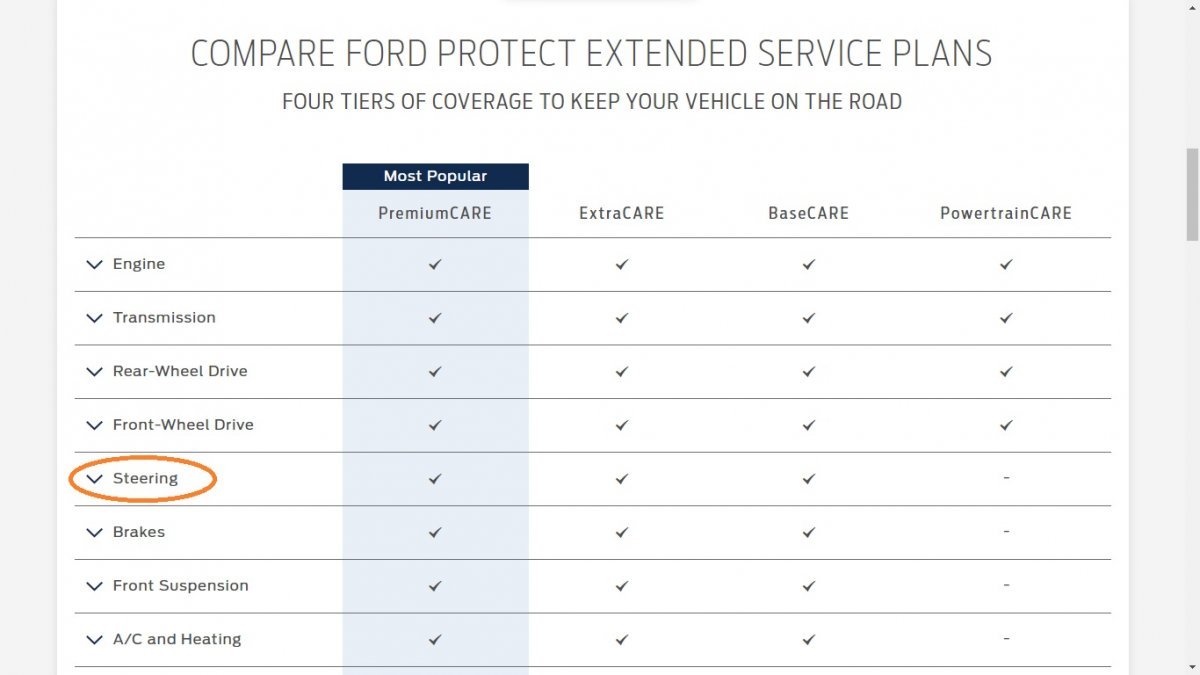
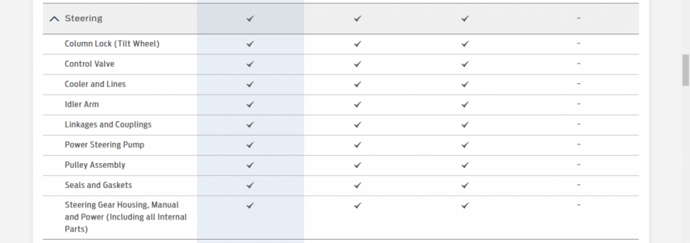
It is worth calling FordProtect to get the answer to your question... The FordProtect website provides a listing of covered items organized by category... Heated steering wheel is not included in the Steering category... The online covered parts listing appears to duplicate the items mentioned in FordProtect Terms and Conditions - January 2021.pdf (download link). If you seek PremiumCare wraparound coverage on your Edge's Blue Advantage Gold Certification, your Edge's non-Powertrain systems may have to be inspected, since only the Powertrain portion of that used vehicle certification remains in force. Ford Blue Advantage Gold Certified Limited Warranty.pdf (download link) Good luck!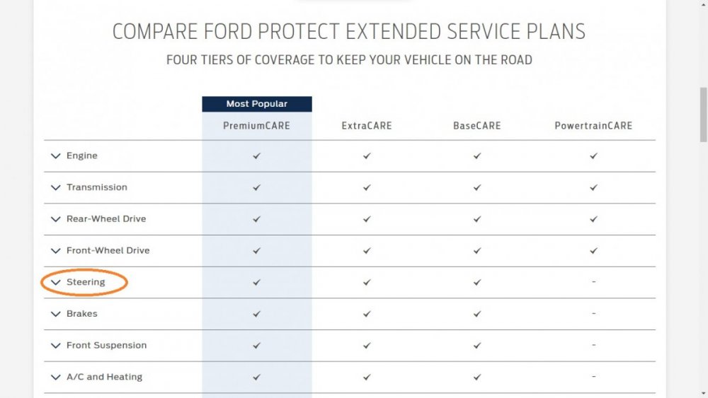
-
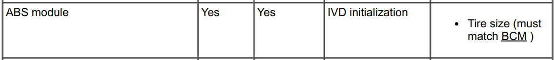
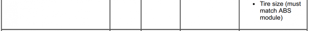
When I changed tire size on my 2015 MKX -- which is a Gen 1+ vehicle and not Gen 2 like your 2016 Edge -- it was necessary to make the tire-size change in the Body Control Module and the ABS module, per the 2014 Edge Workshop Manual's module configuration guidance (edited to apply to your question)... And while it does not include tire size change guidance, and I cannot provide assurance on the correctness of advice it provides, you may enjoy this compilation of Forscan modifications provided by a 2016 Edge owner on Forscan's discussion forum... Document download link> 2016 Ford Edge FORScan Changes Made.pdf If you require original As-Built programming data for your Edge, it should be available from this site, after you select country and language preferences. Good luck!


- 1 reply
-
- 2
-
-
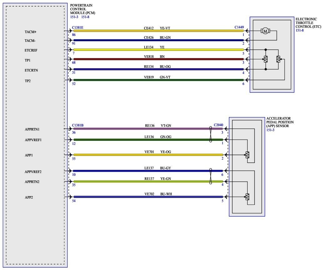
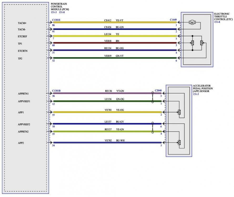
If you are describing limp mode in terms of reduced engine throttle response and speed limiting in the neighborhood of 30 mph, the 2018 Edge Workshop describes Limp Home mode this way... Acceleration Control The acceleration controls consist of the accelerator pedal and sensor assembly. The throttle is controlled by an APP sensor on the accelerator pedal assembly. The APP sensor sends a signal to the PCM in response to throttle pedal movements initiated by the driver. The PCM sends a signal to the electronic throttle control which increases and decreases throttle position. The engine management system electronically operates the throttle of the engine in response to throttle pedal movements initiated by the driver. In the event of a system failure, the engine management system provides a "limp home" mode which allows the car to be driven with limited performance. While the Workshop Manual is not explicit, I expect the context of the described "system failure" is within the Electronic Throttle Control system, consisting of Accelerator Pedal Position (APP) sensor, the Powertrain Control Module (PCM) and the Electronic Throttle Control (ETC) that is integral to the Throttle Body, as depicted in this wiring diagram... The Workshop Manual describes Electronic Throttle Control system-fault notifications and effects... So, absent any Diagnostic Trouble Codes (DTCs) providing guidance, one cross-check for you could be to determine if the cruise control system is presently disabled or is disabled when the wrench light is lit. The Edge Workshop Manual refers diagnostic and testing interests to the Ford Powertrain Control Emissions Diagnosis (PC/ED) Manual, which bins the Limp Home effects under Lack/Loss of Power, and provides Pinpoint Test DK to evaluate Electronic Throttle Control system circuits and components. I have compiled relevant sections from the Edge Workshop Manual and the Ford PC/ED Manual which may provide fuller understanding and useful guidance if your mechanic believes Pinpoint Test DK could be a fruitful course of action. Forum limitations on maximum attachment size prevent me from providing document download links to the document collection here. I will provide you an external download link to the document collection via the Forum messaging system. Good luck!


- 1 reply
-
- 3
-
-

-
During these more frequently occurring -- and frustrating -- Forum service disruptions, the following site determines whether an outage is affecting everyone, or just me (or you)... https://downforeveryoneorjustme.com/fordedgeforum.com Good luck!
-
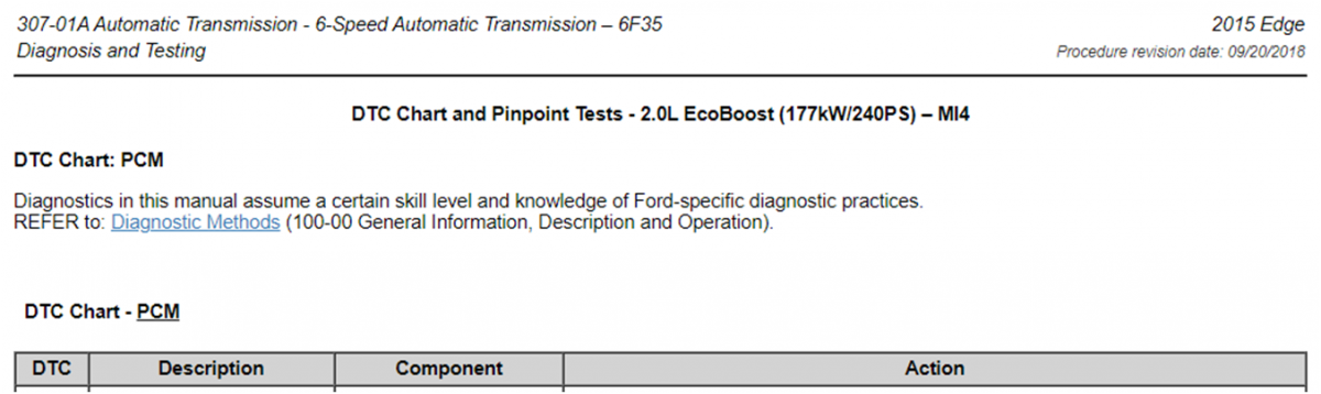
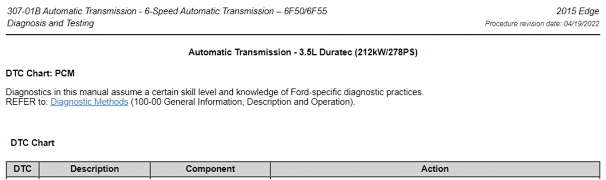
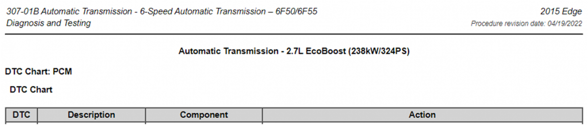
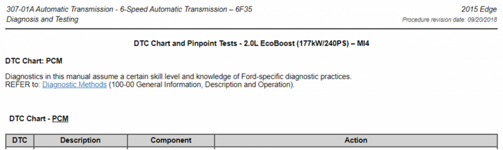
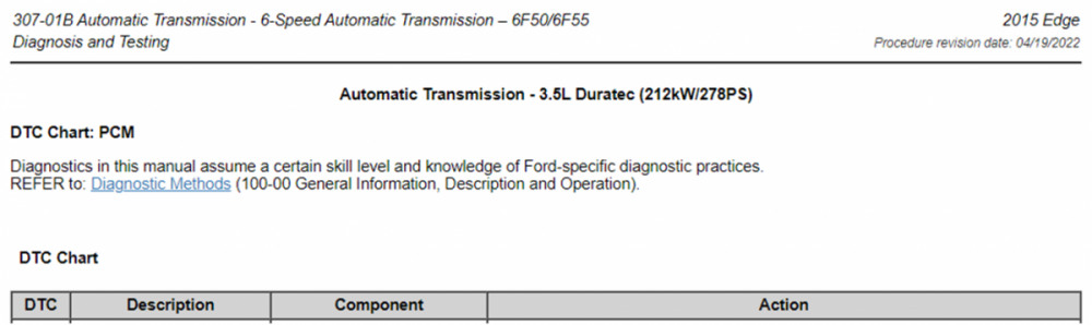
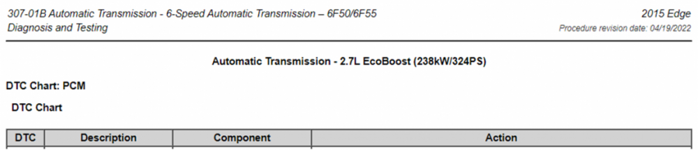
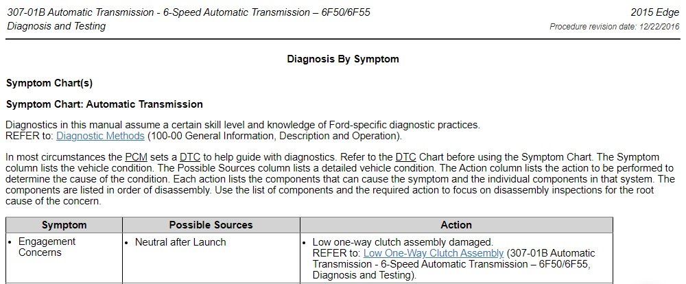
Low One-Way Clutch Assembly is not mentioned in any of the 2015 Edge Workshop Manual's 2.0L EcoBoost I4/6F35, or the 3.5L Duratec V6 & 2.7L EcoBoost V6 6F50/6F55 powertrain combinations of Pinpoint diagnostic tests, which as the name implies, focus upon responding to Diagnostic Trouble Codes (DTCs) with prescribed step-by-step diagnostic procedures to identify the an issue's root cause and the proper corrective action... Note: 2.7L EcoBoost is installed only in the Sport, but is mentioned here to provide full coverage of Edge powertrain combinations which may exhibit the symptom. Your question is validated by the reaction hierarchy within the 6F50/6F55 Symptom Chart image of my prior post... In most circumstances the PCM sets a DTC to help guide with diagnostics. Refer to the DTC Chart before using the Symptom Chart. The Symptom column lists the vehicle condition. The Possible Sources column lists a detailed vehicle condition. The Action column lists the action to be performed to determine the cause of the condition. I don't expect the dealership would want to embark upon a transmission teardown without having a Service technician first-hand experience your Edge's neutral-out behavior, nor do I expect you would want them to, presuming your Edge's Powertrain warranty is expired and there is no extended warranty coverage. On the other hand, you mention the neutral-out behavior occurs more frequently since the transmission fluid change, so the likelihood of a Service tech experiencing the operational symptom is increased. Hopefully, you have Ford ESP or some other extended warranty contract on your Edge to assist with the diagnostic & repair costs. Good luck!
-
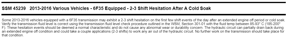
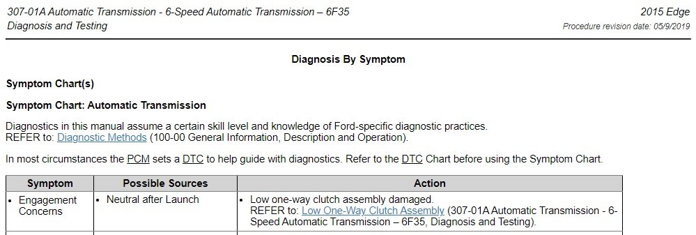
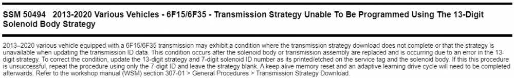
Welcome to the Forum, Len Woodruff ! The 2015 Edge Workshop Manual transmission diagnostic Symptom Charts for both 6F35 and 6F50/6F55 show a "Neutral after Launch" issue being potentially related to "Low one-way clutch assembly damaged" condition, which you may want to mention to the dealership Service personnel involved in your Edge's last visit, to see if they believe it may apply... Note: The following two images have been edited to place the relevant symptom at the top of the list. Document download links> 6F35 Transmission - Diagnosis and Testing - Symptom Chart - 2015 Edge Workshop Manual.pdf Low One-Way Clutch Assembly - 6F35 Transmission - Description and Operation - 2015 Edge Workshop Manual.pdf Low One-Way Clutch Assembly - 6F35 Transmission - Diagnosis and Testing - 2015 Edge Workshop Manual.pdf 6F50 & 6F55 Transmissions - Diagnosis and Testing - Symptom Chart - 2015 Edge Workshop Manual.pdf Low One-Way Clutch Assembly - 6F50 & 6F55 Transmissions - Description and Operation - 2015 Edge Workshop Manual.pdf Low One-Way Clutch Assembly - 6F55 & 6F55 Transmissions - Diagnosis and Testing - 2015 Edge Workshop Manual.pdf I find no transmission-related TSBs issued for 2015 Edge. There are Special Service Messages on 2015 Edge transmission, but they are not related to any neutral-out symptom... Good luck!

-
17 Sport - Bilstein B6 Struts with H&R Springs
Haz replied to bscott94's topic in Brakes, Chassis & Suspension
Document download links> Lower Arm - Removal and Installation - 2017 Edge Workshop Manual.pdf Spring - Removal and Installation - 2017 Edge Workshop Manual.pdf Good luck! -
17 Sport - Bilstein B6 Struts with H&R Springs
Haz replied to bscott94's topic in Brakes, Chassis & Suspension
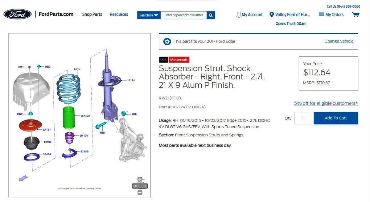
Document download links> Windshield Wiper Pivot Arm - Removal and Installation - 2017 Edge Workshop Manual.pdf Cowl Panel Grille - Removal and Installation - 2017 Edge Workshop Manual.pdf Cowl Panel - Removal and Installation - 2017 Edge Workshop Manual.pdf Front Strut and Spring Assembly - Removal and Installation - 2017 Edge Workshop Manual.pdf Front Stabilizer Bar Link - Removal and Installation - 2017 Edge Workshop Manual.pdf Front Strut and Spring Assembly - Disassembly and Assembly - 2017 Edge Workshop Manual.pdf Perhaps the drag/zoom strut-spring assembly illustration and the related-parts detail tab on this FordParts page can be helpful toward assessing the needed parts... Good luck!
-
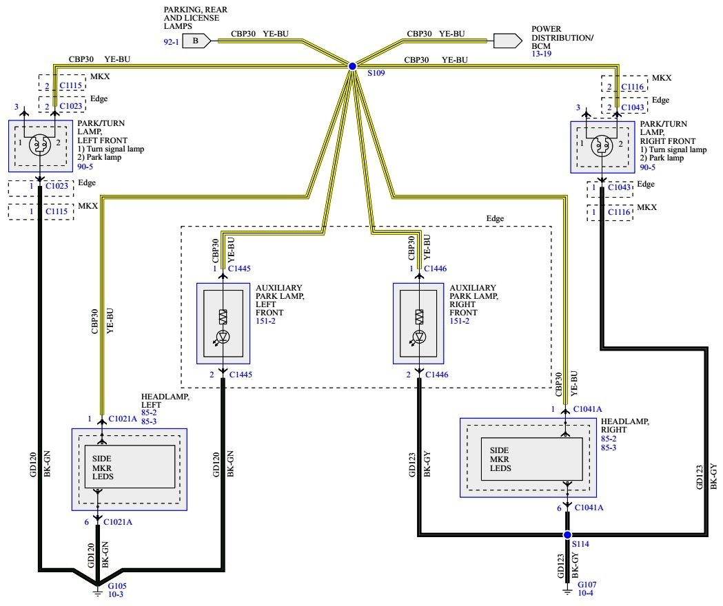
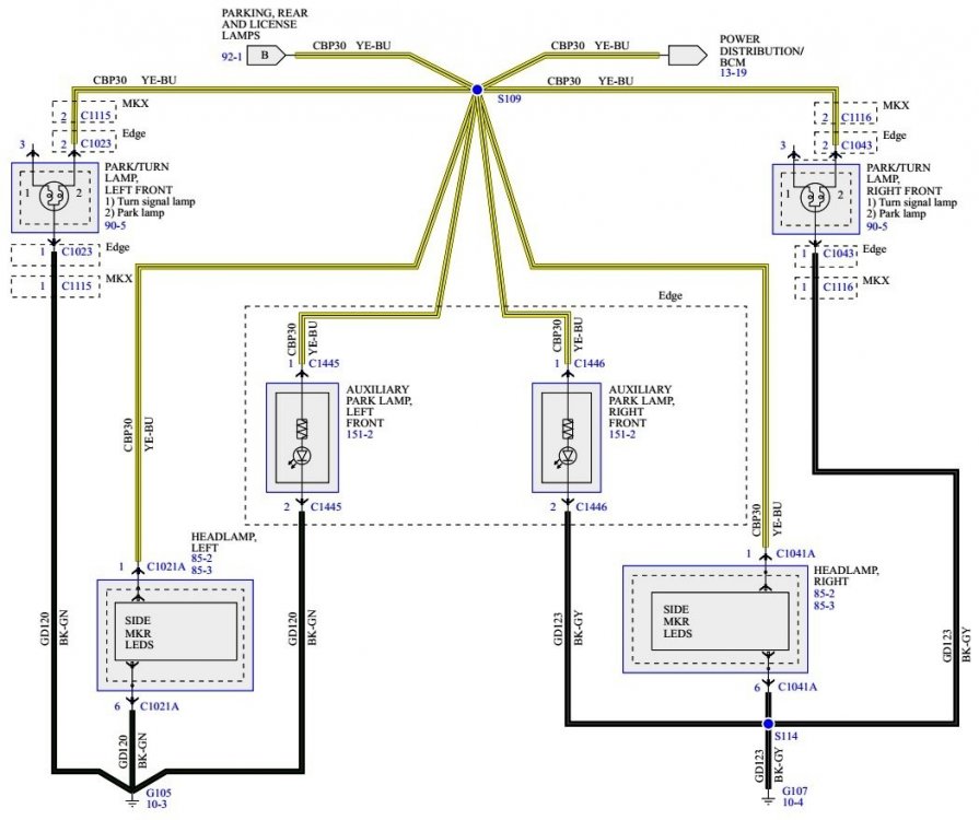
Requested 2011 Edge wiring diagram... Document download links> Headlamps, Side Marker LEDs, Park-Turn Lamps, Auxiliary Park Lamps - Wiring Diagram - 2011 Edge.pdf HEADLAMP, SIDE MARKER LEDs, LEFT - Connector C1021A Details - 2011 Edge.pdf HEADLAMP, SIDE MARKER LEDs, RIGHT - Connector C1041A Details - 2011 Edge.pdf PARK-TURN LAMP, LEFT FRONT - Connector C1023 Details - 2011 Edge.pdf PARK-TURN LAMP, RIGHT FRONT - Connector C1043 Details - 2011 Edge.pdf AUXILIARY PARK LAMP, LEFT FRONT - Connector C1445 Details - 2011 Edge.pdf AUXILIARY PARK LAMP, RIGHT FRONT - Connector C1446 Details - 2011 Edge.pdf Good luck!
-
Premature ball joint failure on Gen 2 Edge
Haz replied to Wesley's topic in Brakes, Chassis & Suspension
Regrets, I cannot offer anything beyond the Workshop Manual procedure. I have messaged the Forum members you mention, asking for their subject matter experience to be shared here. Good luck! -
Premature ball joint failure on Gen 2 Edge
Haz replied to Wesley's topic in Brakes, Chassis & Suspension
Welcome to the Forum, Bill226 ! From the 2017 Edge Workshop Manual... Document download link> Lower Arm - Removal and Installation - 2017 Edge Workshop Manual.pdf Please be aware that some action-step descriptions appear on the page prior to the applicable vehicle illustration. Good luck! -
What have you done to/with your Edge/MKX today?
Haz replied to WWWPerfA_ZN0W's topic in Accessories & Modifications
So, the discussion touched upon an obviously unscrupulous repair shop which was telling a customer that it was necessary to evacuate & inject dye for the shop to detect the vehicle's A/C leak site(s). Because this discussion -- and the Forum -- centers upon Edge/MKX-Nautilus, I presumed it would be useful for all of us to know that, in most cases, A/C leaks are immediately detectable in our vehicles due to the leak detection dye provided from the factory and within several OEM A/C replacement parts. And, that if anyone tells us what you witnessed, that we should do what you did -- walk out. But, you're right, I should refrain from sharing anything in this thread other than what have I done to my Edge/MKX-Nautilus today. Go Vols! -
What have you done to/with your Edge/MKX today?
Haz replied to WWWPerfA_ZN0W's topic in Accessories & Modifications
From the Edge Workshop Manual... Fluorescent Dye Leak Detection NOTE: Fluorescent refrigerant system dye is added to the refrigerant system at the factory to assist in refrigerant system leak diagnosis using a Rotunda-approved UV lamp. Do not add dye to the refrigerant system before diagnosing leaks or after repairs, even if a significant amount of refrigerant has been removed from the system. Replacement suction accumulators, receiver driers, receiver drier elements, and service condensers are shipped with a fluorescent dye wafer included in the desiccant bag which dissolves after approximately 30 minutes of continuous A/C operation. Do not add dye after flushing the refrigerant system because a new suction accumulator, receiver drier or receiver drier element is installed as part of the flushing procedure. NOTE: Ford Motor Company vehicles are produced with R134a or R-1234yf fluorescent dye installed in the refrigerant system from the factory. The location of leaks can be pinpointed by the bright yellow-green glow of the fluorescent dye under a UV lamp. Since more than one leak can exist, inspect each component, line and fitting in the refrigerant system for a leak. NOTE: Use of dye-enhancing glasses or goggles greatly improves the detection of the dye under the UV lamp. NOTE: Not all UV lamps will fluoresce the dye used in Ford vehicles. All Rotunda UV lamps are optimized to fluoresce the dye. NOTE: If the system has been out of refrigerant through the winter the dye at the leak point may have oxidized and may not fluoresce. If this happens, recharge and operate the A/C system to circulate the oil and allow any residual dye to show up at the leak point. It is important to understand that dye adheres to the oil not the refrigerant; the refrigerant carries the oil out of the leak point. Good luck!
FoamMountingTape-McMaster-Carr.jpg.dbbc503d7570e3f571b89b2af1e78411.jpg)
-2017EdgeWorkshopManual.jpg.fea8c9f2de9ecc567f92e47a11267241.jpg)