Haz
-
Posts
1,460 -
Joined
-
Last visited
-
Days Won
392
Content Type
Profiles
Forums
Gallery
Everything posted by Haz
-
The GEN 1/1+ Edge procedure is fairly simple, though the Workshop Manual images are line drawings... Document download link> Liftgate Latch Manual Release - General Procedures - 2011 Edge Workshop Manual with Enlarged Images.pdf The GEN 2 Edge procedure is a bit more elaborate, but at least the Workshop Manual images are more satisfying... Document download link> Liftgate Latch Manual Release - General Procedures - 2015 Edge Workshop Manual.pdf Good luck!
-
The linked Blower Motor document applies to all GEN 2 Edges, from 2015 -2023 model years. The GEN 1 Edge procedure is identical, though the Workshop Manual illustrations are not as graphically pleasing... Document download link> Blower Motor - Removal and Installation - 2007-2014 Edge Workshop Manuals.pdf Good luck!
-
TSB 21-2389 is the most recently released Service Procedure for this issue... Document download link> TSB 21-2389 - 8F35 Transmission - Shudder-Buck-Jerk While Driving Up To 35 MPH (57 Km-H) - Built On Or Before 11-Mar-2021.pdf Good luck!
-
2020 Wiring Diagram (6 speaker system)
Haz replied to DBBobbyT's topic in Audio, Backup, Navigation & SYNC
Workshop Manual image of factory-installed Subwoofer mounted located behind RH Loadspace Trim Panel... Good luck!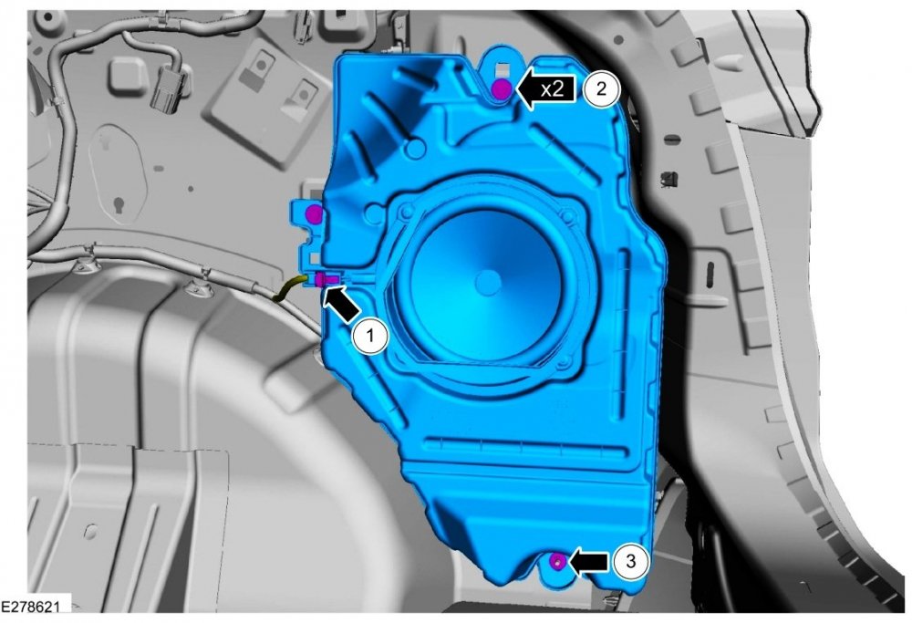
-
SSM 51778 - 2020-2022 Various Vehicles - Audio Inoperative - No Sound From Audio Speakers - No Communication With ACM Or DSP - DTC U0184, U0237 And/Or U0238 Some 2020-2021 Escape built on/before 23-Nov-2021, 2021 F-150 built on/before 08-Oct-2021, 2021 Mustang Mach-E built on/before 29-Mar-2021, 2021 Expedition built on/before 05-Aug-2021, 2021 Explorer built on/before 27-Sep-2021 and 2020-2022 Edge may exhibit a concern of the audio system does not power on, no sound from audio speakers, chimes default to coming through the instrument cluster, no communication with audio control module (ACM) or digital signal processor (DSP) module, and/or diagnostic trouble code (DTC) U0184, U0237 and/or U0238. To correct the condition, perform a hard reset of the DSP by disconnecting the 12-volt battery. Reprogram the DSP module using the latest version of the appropriate Ford diagnostic scan tool. For claiming, use causal part 18B849 and any applicable labor operations in Section 10 of the Service Labor Time Standards Manual.
-
2020 Wiring Diagram (6 speaker system)
Haz replied to DBBobbyT's topic in Audio, Backup, Navigation & SYNC
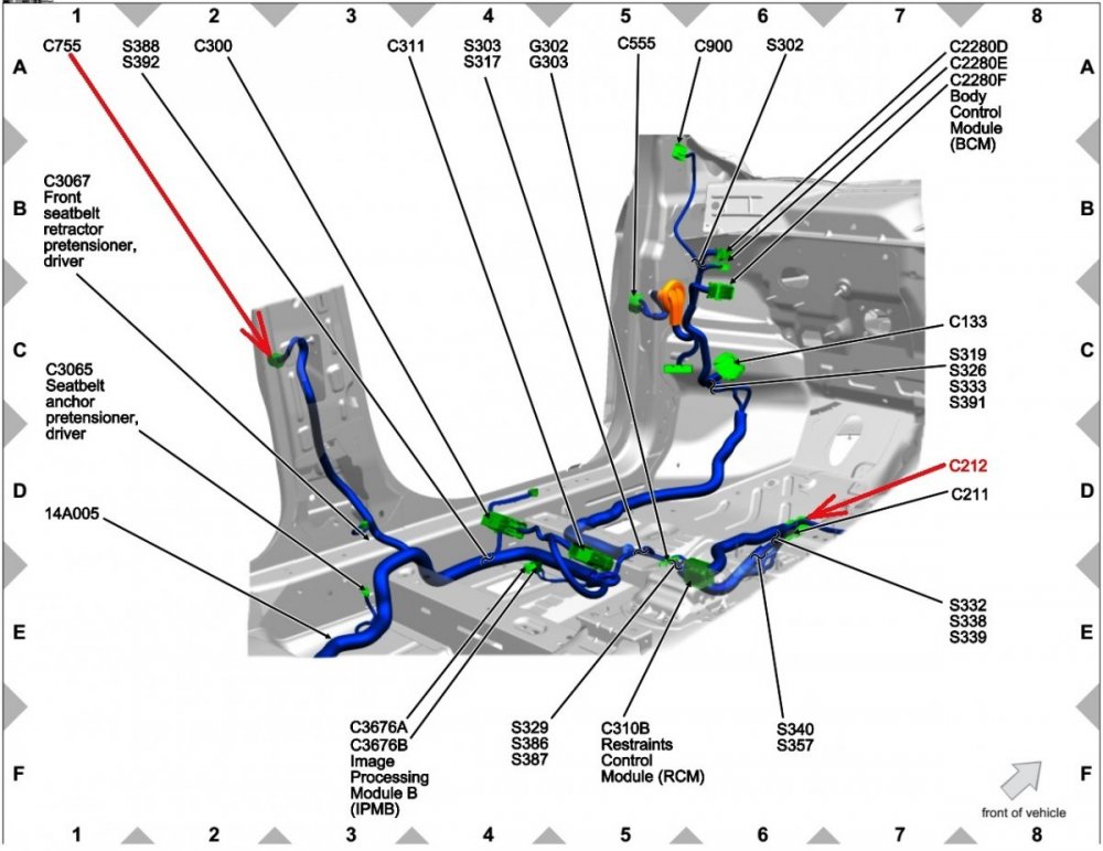
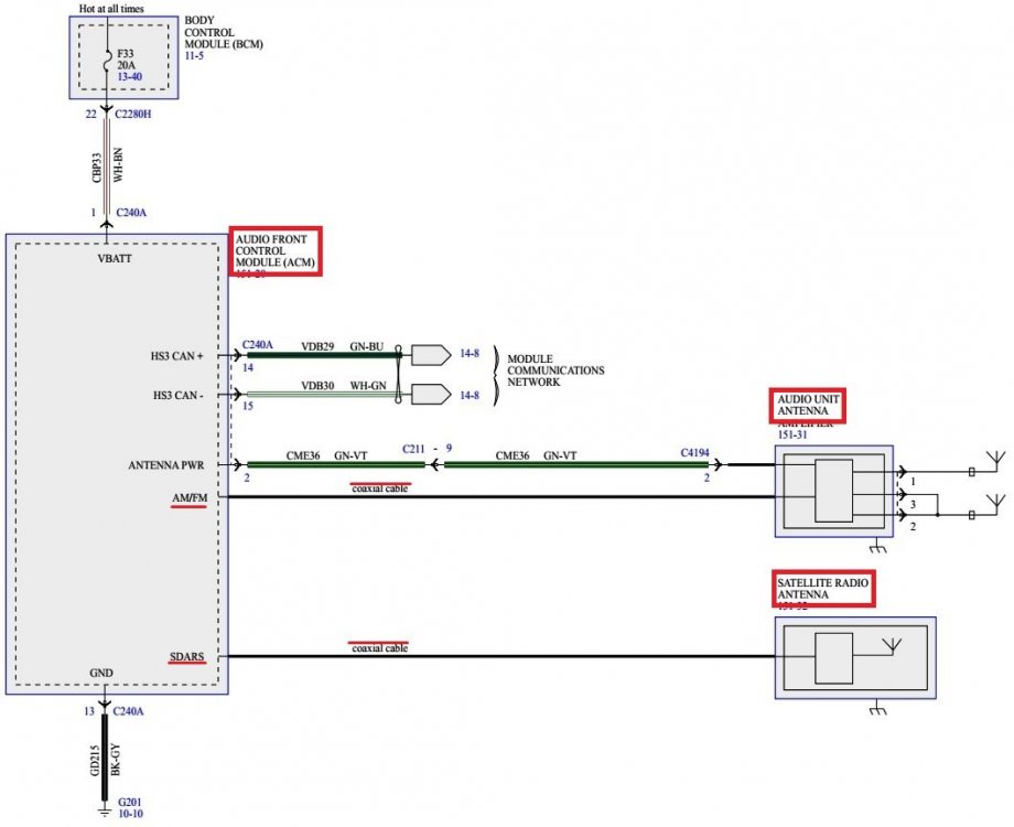
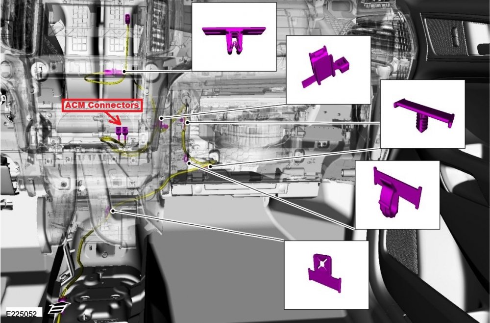
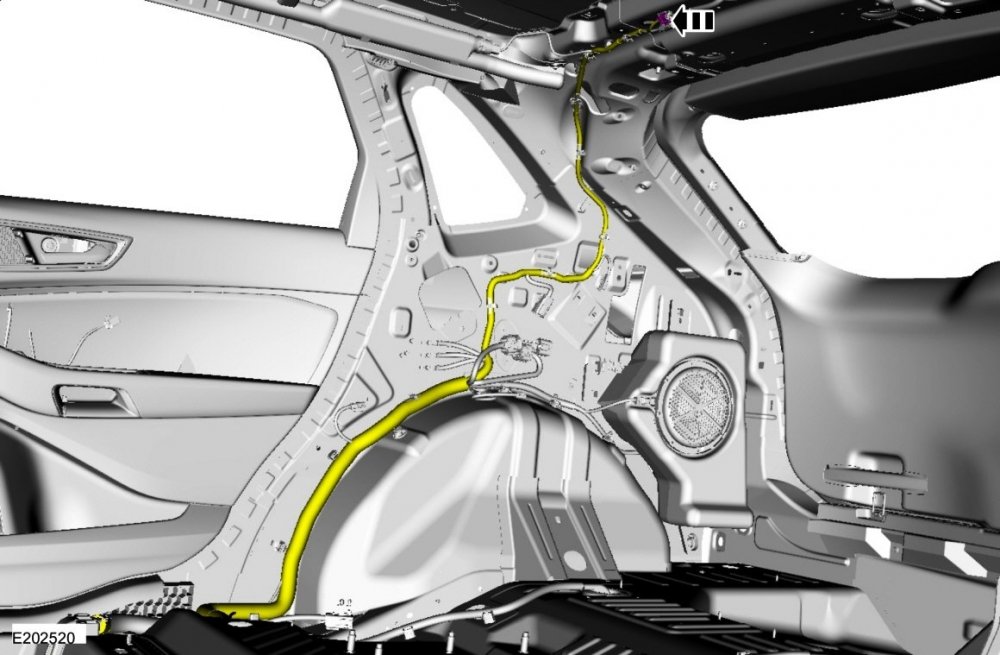
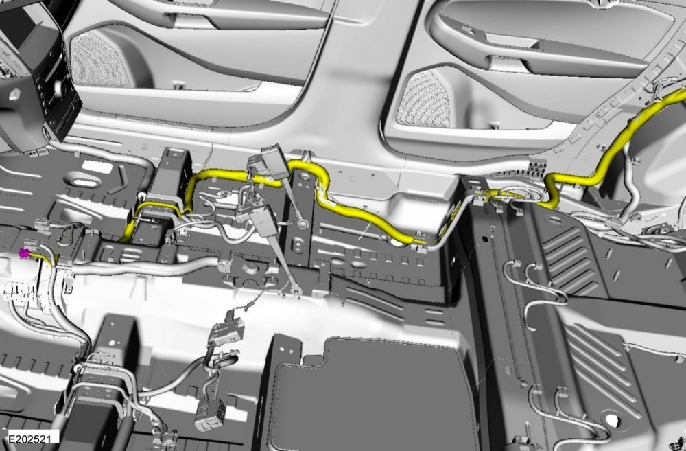
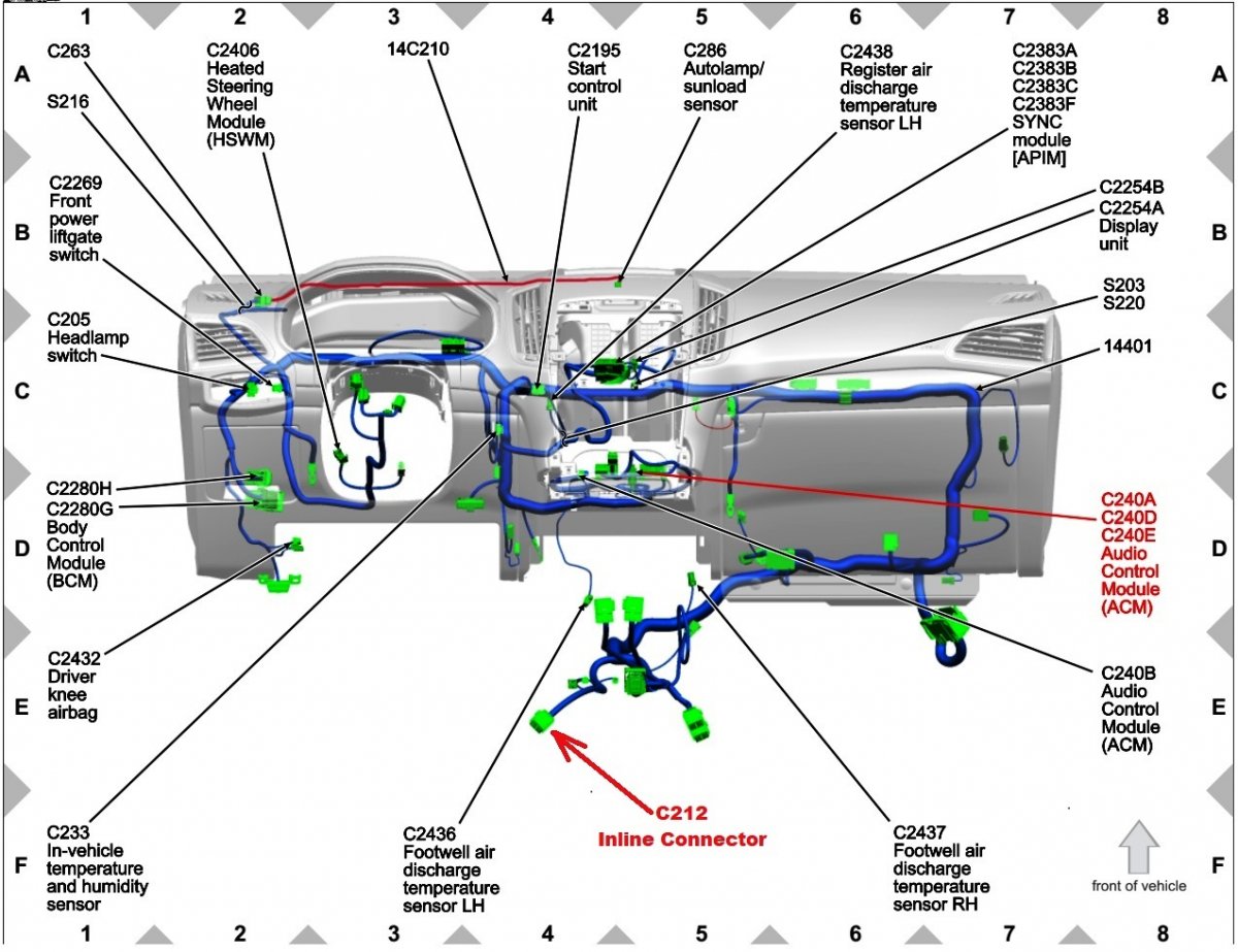
Front Audio Control Module (ACM) C240A via Instrument Panel main harness to Inline Connector C212 at front of Center Console... Inline Connector C212 to Inline Connector C755 on LH B-Pillar... Inline Connector C212 also serves Inline Connector C855 on RH B-Pillar... ACM to 6-Speakers Wiring Diagram... Document download links> AUDIO CONTROL MODULE (ACM) - Connector C240A Details - 2022 Edge.pdf Inline Connector C212 Circuit-Pin Details - 2022 Edge.pdf Inline Connector C755 Circuit-Pin Details - 2022 Edge.pdf Inline Connector C855 Circuit-Pin Details - 2022 Edge.pdf REAR DOOR SPEAKER LH - Connector C702 Details - 2022 Edge.pdf REAR DOOR SPEAKER RH - Connector C802 Details - 2022 Edge.pdf Good luck!6-SpeakerWiringDiagram-2022Edge.thumb.jpg.45dd91b3569fdb62f0e026b70e9b82d6.jpg)

6-SpeakerWiring-InlineConnectorC855-RHB-Pillar-2022Edge.thumb.jpg.bb715e0a85a300c8b98f6cc4dea15ddb.jpg)
-
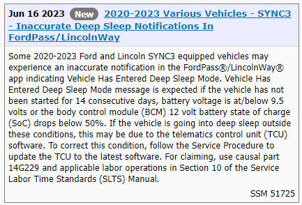
Thus far, Ford has released three Special Service Messages relating to the Deep Sleep Notification issue: SSM 50975 in July 2022; SSM 51449 in March 2023; SSM 51725 in June 2023; All are contained in this Recalls, TSBs & Warranty Forum discussion. Good luck!
-
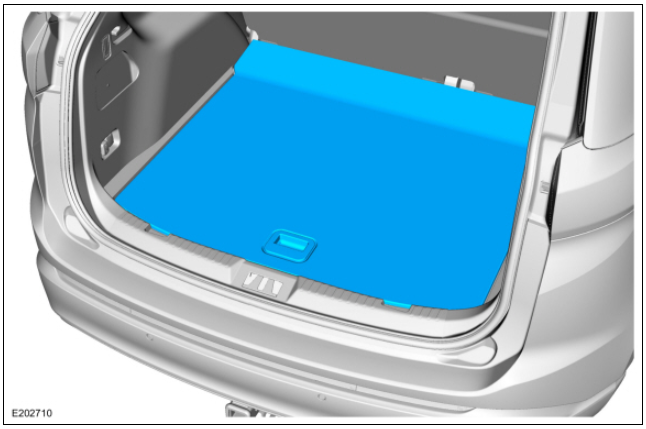
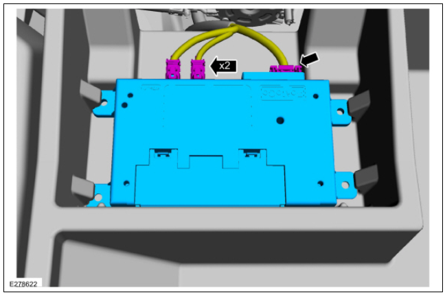
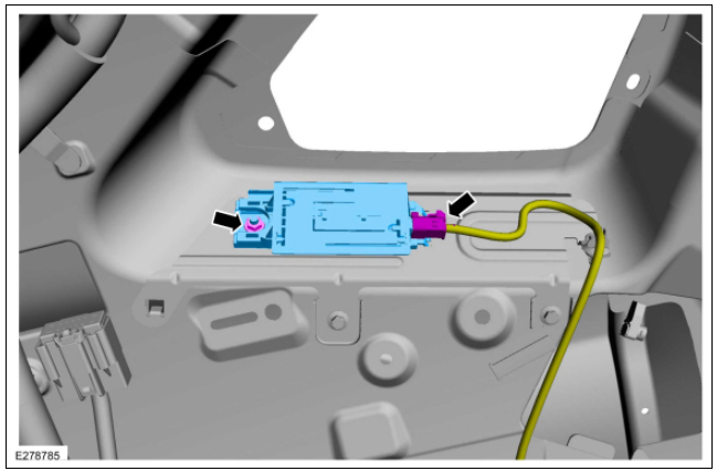
This recent Special Service Message describes the conditions that rightfully trigger a Deep Sleep notification, and if, in 2020-2023 model year vehicles, the notification occurs apart from those expected conditions, that a Telematics Control Unit (TCU) software update may be needed... The 2019 Edge Workshop Manual offers this explanation, which may be comparable to the Ford website information you mention... SYNC Connect (if equipped) NOTE: Depending on the notification settings, the vehicle may report a “Deep Sleep Mode” on supported mobile Apps. This occurs when battery voltage drops below a level necessary for correct vehicle operation or the vehicle has been inactive for a number of days. The SYNC Connect system (when activated) can be used to provide remote connectivity through the FordPass mobile phone application. It can monitor certain vehicle systems and carry out vehicle functions such as: reading the fuel level and odometer. receiving remote alerts and notifications. carrying out or scheduling remote starts (if enabled through the IPC ). using the vehicle locator. vehicle lock/unlock control and vehicle lock/unlock status. NOTE: If vehicle battery voltage falls below the minimum required or the vehicle has been inactive beyond a designated time limit, the TCU turns off until the next engine running event to preserve battery power. The connected mobile device App reports a deep sleep mode if notifications are turned on. Refer to the mobile device App information to set notifications and for a list of disabled features when the vehicle is in deep sleep mode. Workshop Manual images showing TCU location... TCU Antenna module is located behind LH Loadspace trim panel... Good luck!
-
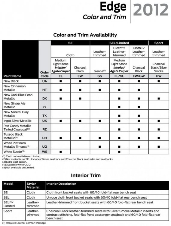
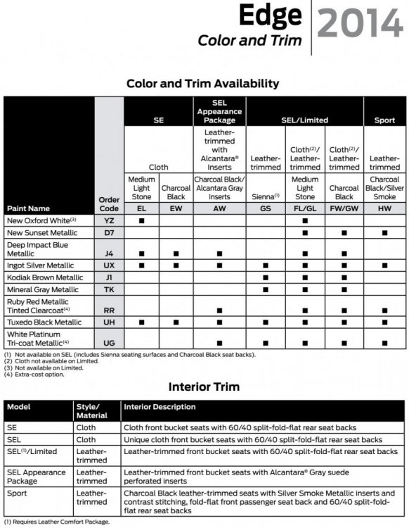
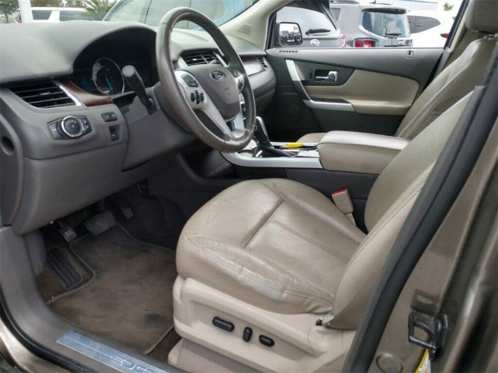
Comparison of 2012 Edge and 2014 Edge interior color availability... Versus... ua Presumably, your Edge's seats that you describe as being Sandstone are actually Medium Light Stone... From a CarGurus.com listing, VIN of 2014 Edge Limited with Medium Light Stone seats: 2FMDK3KC5EBB63684... Photo of this 2014 Edge, showing seat upholstery design and color consistent with photo you posted... Good luck!


-
Special Service Message 51762 - 2021-2023 Various Vehicles - Navigation Feature Unable To Change From Miles To Kilometers On SYNC 4 Equipped Vehicles Some 2021-2023 Ford and Lincoln vehicles equipped with SYNC 4 may exhibit the navigation feature in the center display screen only displaying imperial units and not being able to change to metric. This may be due to the software level of the SYNC module (APIM). This issue does not affect vehicle durability and no additional diagnosis or service is required for this condition at this time. Inform customers that engineering is currently working on a solution for this condition and will be released via Ford Power-Up software updates delivered over-the-air (OTA) expected in September 2023. Software will update automatically if vehicle connectivity is enabled in the vehicle’s settings. Schedule a service visit for customers who have disabled vehicle connectivity or who report that they did not receive the update in September 2023. Monitor OASIS for additional information.
-
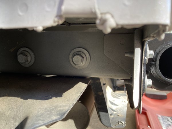
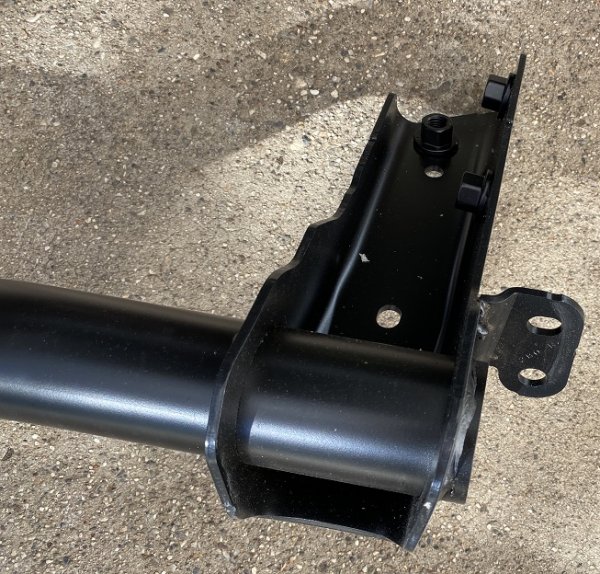
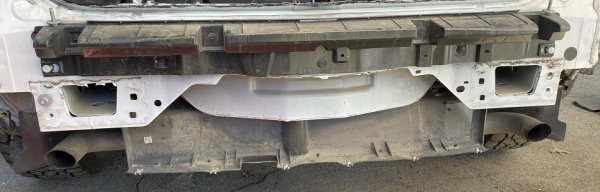
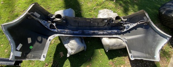
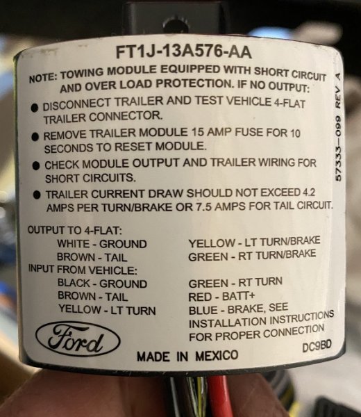
2017 Edge Sport Ford OEM Trailer Hitch Install
Haz commented on TheTurboEdge's gallery album in Member Photo Albums
 Vinnie75... Link to this FordParts page Link to this FordParts page Document download links> Hands-Free Liftgate Actuation Upper Sensor - Removal and Installation - 2017 Edge Workshop Manual.pdf Hands-Free Liftgate Actuation Lower Sensor - Removal and Installation - 2017 Edge Workshop Manual.pdf Good luck!
 -
-
Welcome to the Forum, Jim_B ! These Charging System references may be helpful... Document download links> Charging System - Principles of Operation - 2008 Edge Workshop Manual.pdf Charging System Pinpoint Test D - Diagnosis and Testing - 2008 Edge Workshop Manual.pdf Charging System Wiring Diagram - 2008 Edge.pdf Generator - Connector C102A Details - 2008 Edge.pdf Powertrain Control Module - Connector C175B Details - 2008 Edge.pdf Powertrain Control Module - Connector C175B Location - 2008 Edge.pdf Powertrain Control Module (PCM) - Removal and Installation - Reference For PCM Location - 2008 Edge Workshop Manual.pdf Good luck!
-
How to remove plastic cover under pax seat
Haz replied to F4Gary's topic in Interior, A.C., Heat, Interior Trim
Removing two Torx screws will allow you to reposition and/or remove the Front Seat Climate Control Module (SCME)... Document download links> Front Seat Climate Control Module (SCME) Location - 2017 Edge.pdf Front Seat Climate Control Module (SCME) - Removal and Installation - 2017 Edge Workshop Manual.pdf Good luck!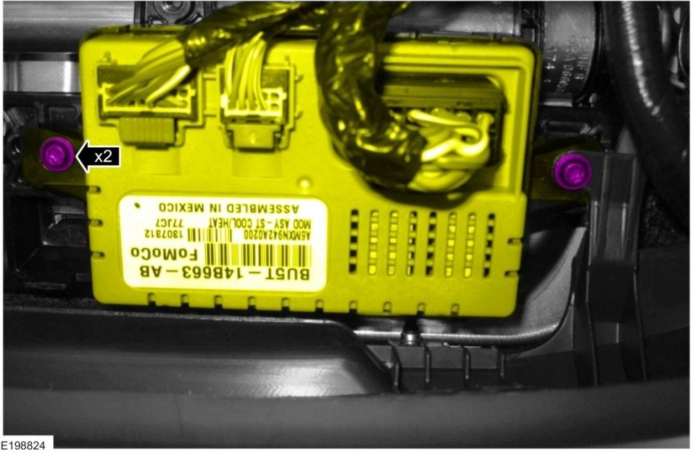
-
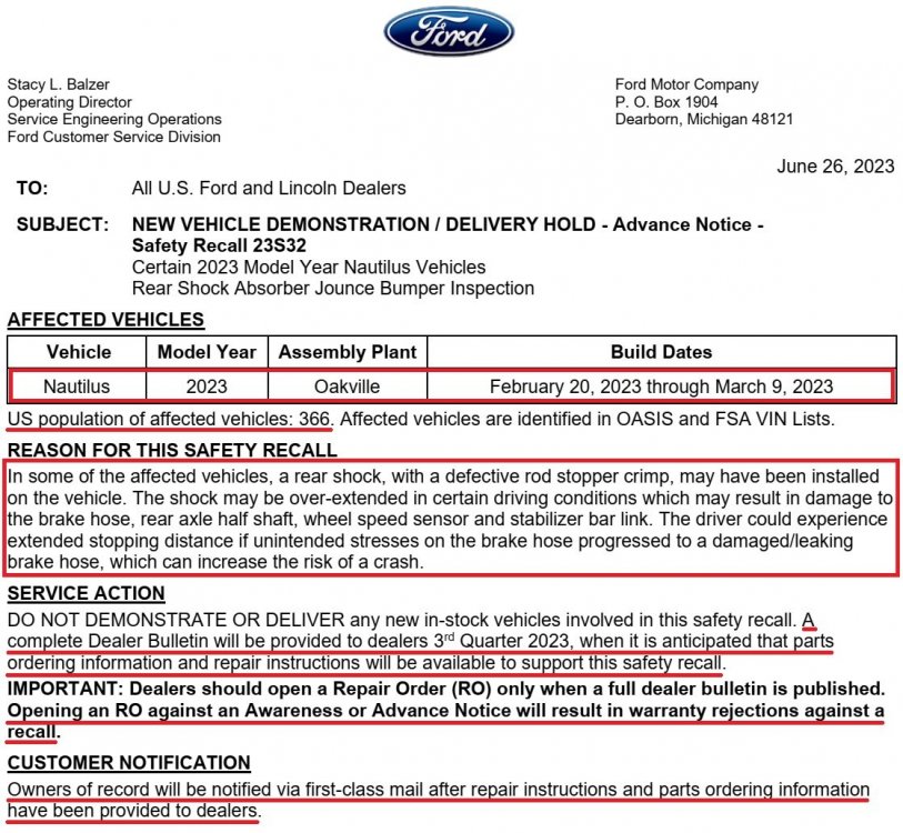
Ford has issued this Advance Notice to Dealers about the upcoming Safety Recall 23S32 affecting certain 2023 Nautilus vehicles, shown below. Until uniquely identified replacement parts are available in sufficient number to equitably address the population of vehicles involved, this Safety Recall is not actionable, that is, dealers have been directed to wait until the complete Dealer Bulletin with parts-ordering information is provided to them in the 3rd Quarter 2023. I will update this post when the complete Notice To Dealers letter is released. Good luck!
- 1 reply
-
- 2
-

-
Clearing DTCs does not necessarily eliminate the underlying causes that trigger them, but can create a clean slate upon which your Edge's current problem can be written, via its DTC. The DTC or Symptom chart provides direction on the Pinpoint Test used to identify and resolve the issue. If you've not yet scanned your Edge, that is Step 1. Good luck!
-
From the 2009 Edge Workshop Manual.... Charging System Principles of Operation The PCM-controlled charging system, or "Smart Charge" charging system, determines the optimal voltage set point for the charging system and communicates this information to the voltage regulator. The "Smart Charge" charging system is designed to set 1 of 5 DTCs any time a charging system fault is present. All of the DTCs can set continuous faults, but not all DTCs will set as on-demand faults. DTC KOEO KOER Continuous P0563 X X X P0620 X P0625 X X P0626 X X P065B X This system uses 2 communication lines between the PCM and the generator/voltage regulator. Both of these communication lines use Pulse-Width Modulation (PWM) . The generator communication (GENCOM) line communicates the desired set point from the PCM to the voltage regulator. The generator monitor (GENMON) line communicates the generator load and error conditions to the PCM. The GENCOM command is only sent by the PCM when it is necessary to adjust the voltage set point. If the set point does not need to be changed, several seconds may elapse between PCM GENCOM commands. This normal operation will appear in the PID as occasional "bursts" of pulse-width commands. The third pin on the voltage regulator, the A circuit pin, is a circuit dedicated to monitor or sense battery voltage. The PCM simultaneously controls and monitors the output of the generator. When the current consumption is high or the battery is discharged, the PCM will raise engine speed as needed to increase generator output. The generator charges the battery and at the same time supplies power for all of the electrical loads that are required. The battery is more effectively charged with a higher voltage when the battery is cold and a lower voltage when the battery is warm. The PCM is able to adjust the charging voltage according to the battery temperature by using a signal from the Intake Air Temperature (IAT) sensor. The PCM also uses other inputs to control charging system voltage such as the Vehicle Speed Sensor (VSS) and Engine Coolant Temperature (ECT) . This means the voltage set point is calculated by the PCM and communicated to the voltage regulator by the GENCOM circuit based on the needs of the vehicle and the conditions. To minimize engine drag when starting the engine, the PCM does not allow the generator to produce any output until the engine has started. The PCM turns off the generator during cranking to reduce the generator load and improve cranking speed. Once the engine starts, the PCM slowly increases generator output to desired voltage. The PCM controls the charging system warning indicator by sending a message over the High Speed Controller Area Network (HS-CAN) to the Instrument Cluster (IC) module. The IC module will then control charging system warning indication based on the message from the PCM. If equipped with a charging system warning indicator, the IC module will turn the indicator ON or OFF. If equipped with a message center, the IC module will display a CHECK CHARGING SYSTEM message. When the ignition is ON and the engine is OFF on vehicles equipped with a message center, the CHECK CHARGING SYSTEM message may not be displayed. For information regarding the IC module and message center, refer to Section 413-01. Under certain circumstances, the charging system may have a concern, but still keep the battery charged and the vehicle running. GENCOM is normally used to initiate charging, but the generator may charge with a fault in this circuit. If the engine is operated at greater than 2,000 rpm momentarily, the generator may "self-excite" or start charging on its own. The charging system warning indicator is illuminated and/or CHECK CHARGING SYSTEM message is displayed, and the generator operates in a default mode (approximately 13.5 volts) until the engine is turned off. When the engine is restarted and the engine is operated at greater than 2,000 rpm momentarily, the generator may again self-excite and again the charging system warning indicator is illuminated and/or CHECK CHARGING SYSTEM message is displayed. The PIDs and their associated descriptions used in the charging system diagnosis are listed below: PID Chart PID Description Normal Display Associated Circuit Name Connector, Circuit GENMON Generator monitor (GENMON) Constant fluctuating percentage 3%-98% Generator monitor (GENMON) C102A-1, CDC15 (VT) GENCMD Generator command (GENCMD) Fluctuating percentage or small intermittent bursts 3%-98% Generator communication (GENCOM) C102A-2, CDC10 (BU/OG) GENVDSD Generator voltage desired Voltage varies by vehicle needs - May be controlled by an output state control — — GENFIL Generator fault indicator lamp command/status OFF charging system is OK — — GENCMD_LF Generator command line fault NO FAULT if GENCOM circuit (GENCMD PID) is OK — — GENMON_HZ Generator monitor frequency NO FAULT if GENCOM frequency is OK — — VPWR Module supply voltage Within 0.5 volt of battery voltage — — RPM Engine revolutions per minute Engine rpm - May be controlled by an output state control — — NOTE: If no charging system DTCs are present, the charging system is operating correctly. If the charging system has a concern, it usually sets a charging system DTC. Document download links> Charging System - Diagnosis and Testing - Principles of Operation - 2009 Edge Workshop.pdf Charging System - Diagnosis and Testing - Diagnostic Trouble Code (DTC) Chart - 2009 Edge Workshop.pdf Charging System - Diagnosis and Testing - Symptom Chart - 2009 Edge Workshop.pdf Charging System - Diagnosis and Testing - Pinpoint Tests - 2009 Edge Workshop .pdf Good luck!
-
Windshield Replacement
Haz replied to 1004ron's topic in Glass, Lenses, Lighting, Mirrors, Sunroof (BAMR), Wipers
FordParts page link Good luck!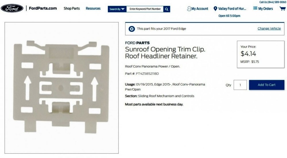
-
Windshield Replacement
Haz replied to 1004ron's topic in Glass, Lenses, Lighting, Mirrors, Sunroof (BAMR), Wipers
Sorry, I've been away and didn't know I was being summoned. Document download links> Roof Opening Panel Front Trim - Removal and Installation - 2017 Edge Workshop Manual.pdf Roof Opening Panel Side Trim - Removal and Installation - 2017 Edge Workshop Manual.pdf Good luck! -
Welcome to the Forum, Sylvester! I understand from your Forum message that your Edge is a 2015 SEL 2.0L EcoBoost. The following Edge Workshop Manual Warning Chimes section describes the source and characteristics of Edge audible warning chimes... Documents download link> Warning Chimes - System Operation and Component Description - 2015 Edge Workshop Manual.pdf Seatbelt Minder Deactivating-Activating - General Procedures - 2015 Edge Workshop Manual.pdf I see the Lane Keeping Alert Warning System Chime is a triple 1/4-second chime pattern for hands-off the steering wheel, but Lane Keeping is not operable below 64km/hr (40 mph), so that doesn't fit your circumstances. The PRNDL Not In Park Warning Chime is a triple 1/2-second chime pattern, but it is accompanied by a Not In Park text box in the Message Center, so that clearly doesn't fit either. Look over the Warning Chimes document to see if any described system/circumstance fits what your Edge exhibits -- if there is a next time. The Belt-Minder Feature chime fits the profile of low speed/starting out, so take a closer look at that description, perhaps, in case you had a weighty item on the passenger seat. Getting your Edge scanned for Diagnostic Trouble Codes (DTCs) may be useful, if the condition persists. Good luck!
-
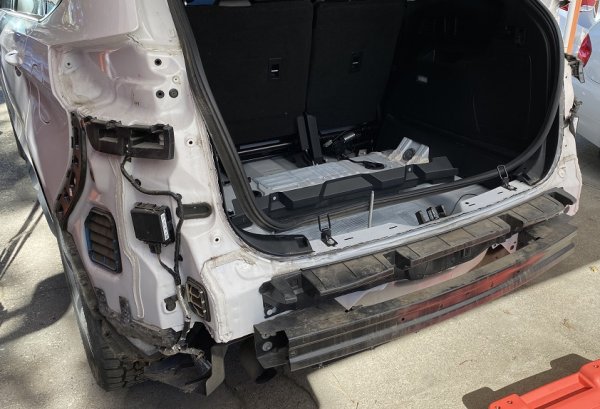
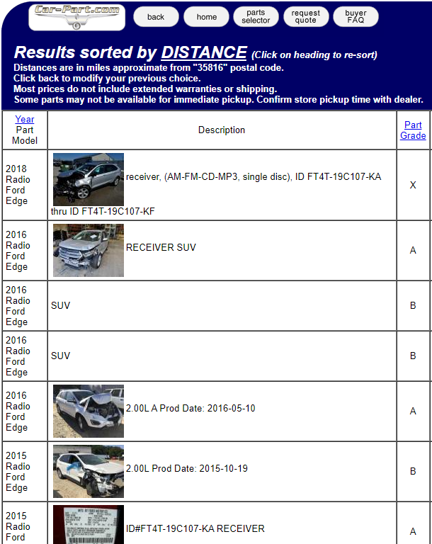
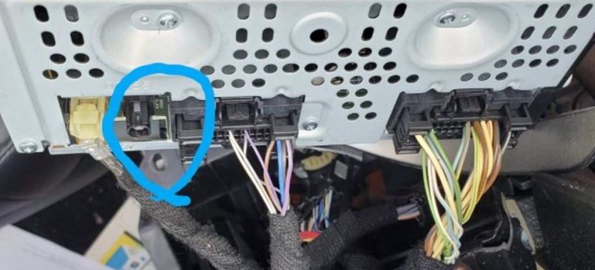
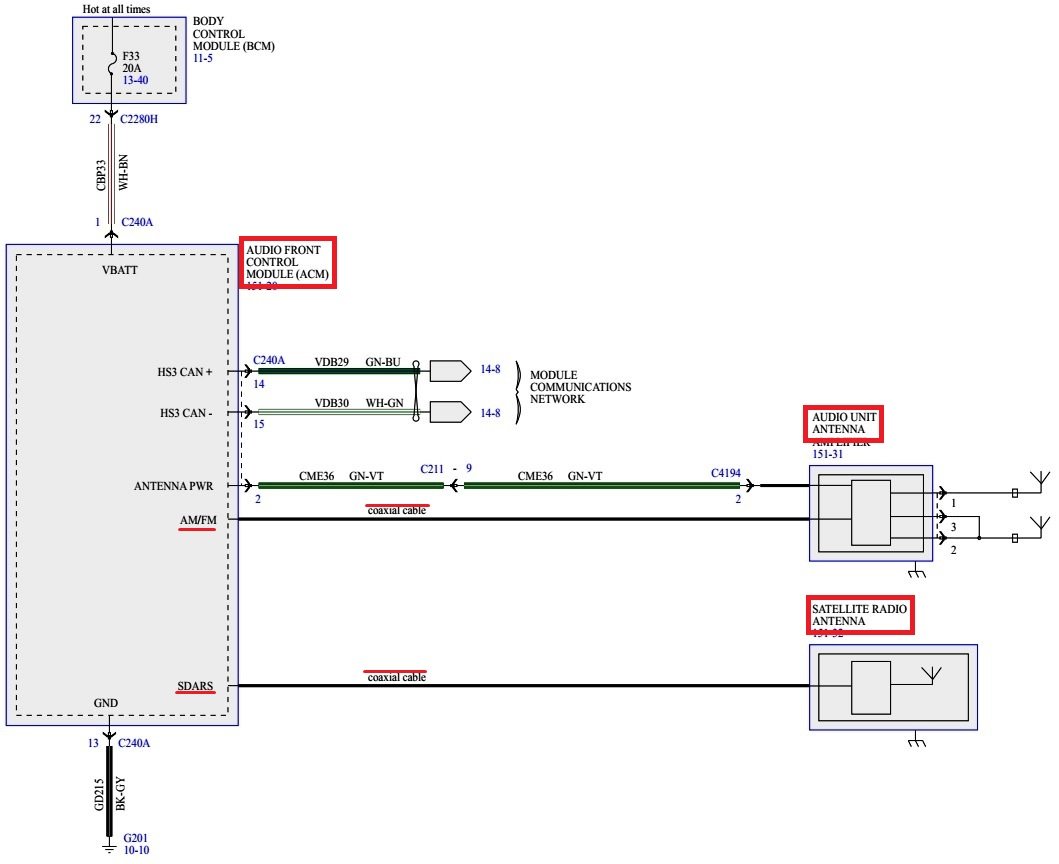
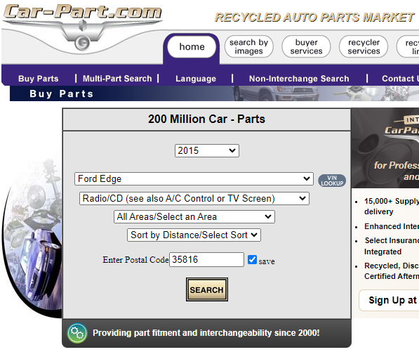
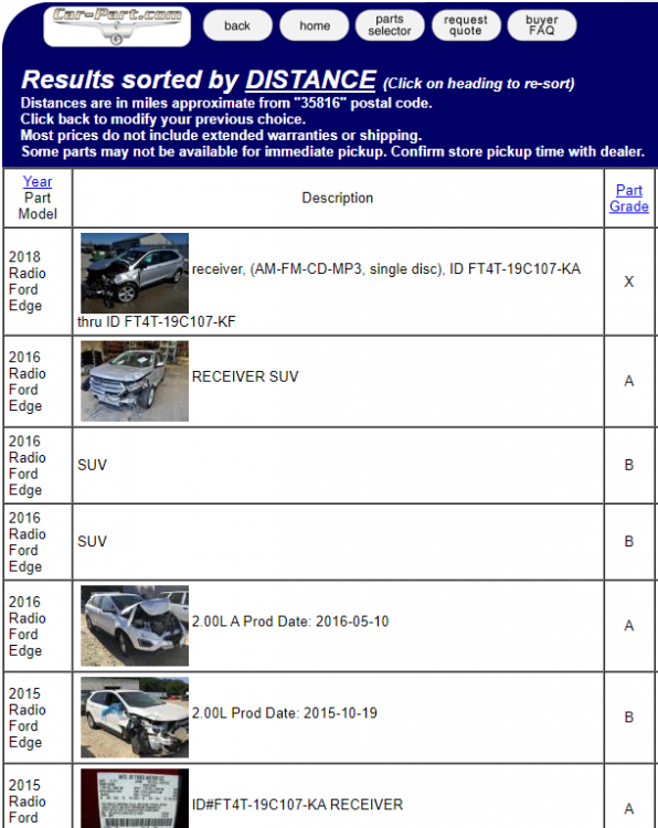
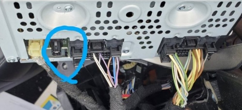
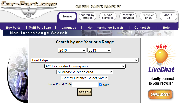
Welcome to the Forum, Chris24k ! As enigma-2 mentions, seeking a cutoff cable end from a salvage yard should be far easier than replacing the full antenna cable, which I'll describe shortly. In order to locate a potential connector-donor Edge in your area, you could try the Car-Part.com search engine... ...and designating on the secondary Search page... ...and while the search results are for Edges equipped with the same radio/Front Audio Control Module (ACM) as your Edge... ...this should ensure that the antenna cable-end connector-cutoffs the salvage yard provides you will match-up with your Edge's ACM/radio... If you know your way around a soldering iron and some electrical tape, this will be easier than entirely replacing the front-to-rear antenna cables, as described in the following Workshop Manual section... Document download links> Audio Unit Antenna Cable - Vehicles With Touchscreen Display - Removal and Installation - 2015 Edge Workshop Manual.pdf Wiring Repair Job Aid (Partial).pdf It's worth noting that the ACM wiring diagram lacks any antenna cable-end connector identifier and also shows the antenna cable is one-piece from rear-to-front... ...whereas the replacement antenna cable is two-piece and is zip-tied to the harnesses containing the original antenna cable from the rear ...along the floor... ..and the second antenna cable piece is routed up to the ACM... Good luck!


- 4 replies
-
- 1
-
-
- wiring
- electronics
- (and 2 more)
-
Special Service Message 51721 - 2022 Edge/Explorer - Illuminated MIL When Shifting Into Park With DTC P0919 And/Or P0929 Some 2022 Edge vehicles built on and after 16-Nov-2022 and 2022 Explorer vehicles built on and after 20-Sep-2022 may exhibit a brief illumination of the malfunction indicator lamp (MIL) when the vehicle is shifted into park (P) with diagnostic trouble code (DTC) P0919 and/or P0929 stored in the gear shift module (GSM). This may be due to the GSM software. To correct this condition, update the software in the GSM using the latest software level of the Ford Diagnosis and Repair System (FDRS). For claiming use the causal part number 7P155 and applicable labor operations in Section 07 of the Service Labor Time Standards (SLTS).
- 1 reply
-
- 2
-
-
Ford continues to inform Service technicians on Telematics Control Unit (TCU) software update to remedy inaccurate Deep Sleep notifications for SYNC 3 equipped 2020-2023 vehicles...
-
One of several items included in Ford's new Service Awareness Newsletter for vehicle-servicing professionals... The Service Awareness Newsletter is an informal communication that contains information that may not be presently available in a TSB, SSM, GSB, or other electronic communication. Articles include information on warranty, technical service tips and other service information. Low Refrigerant Level At Low Time In Service Some 2022 and later Ford and Lincoln vehicles may exhibit low or no refrigerant in the air conditioning (A/C) system at low time in service. A/C system fill is verified during production on all vehicles using very accurate equipment so it is very likely the vehicle does have a leak and very unlikely the vehicle left the plant without charge. In order to prevent repeat returns for the same customer, the system should be leak checked and repaired as required prior to adding refrigerant and releasing the vehicle.
-
Blend door actuator is good, post for cam arm is not
Haz replied to pagraber's topic in Interior, A.C., Heat, Interior Trim
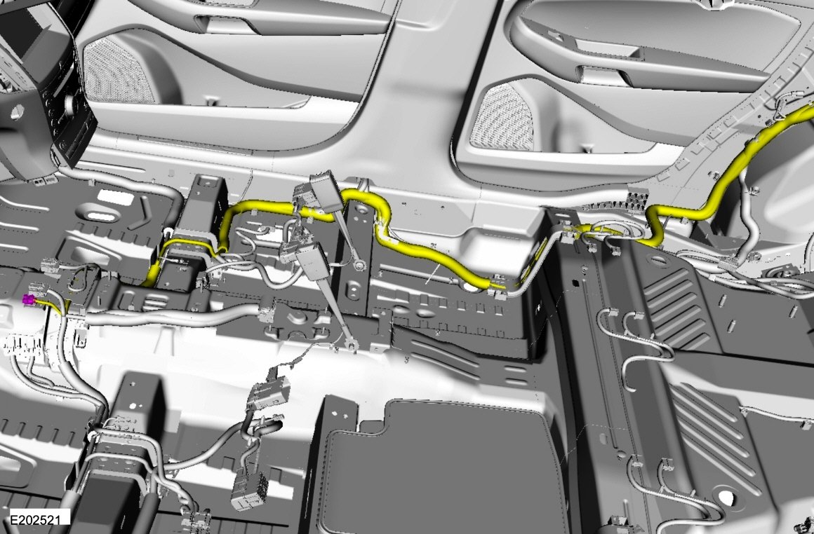
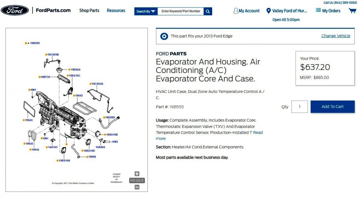
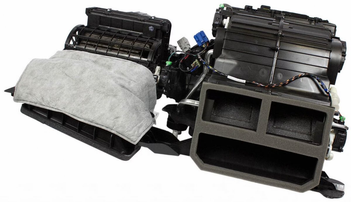
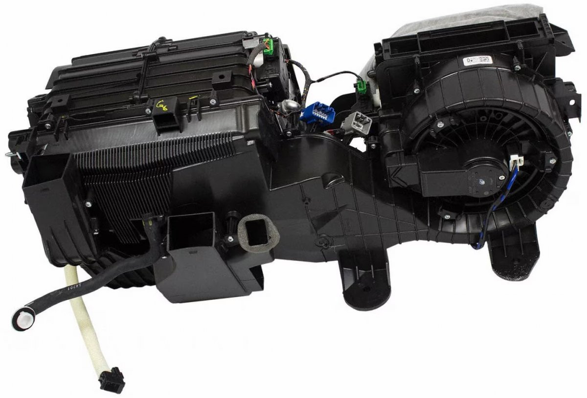
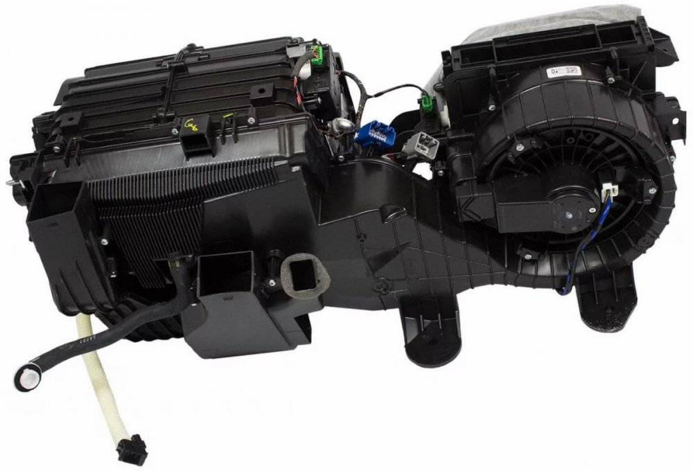
Welcome to the Forum, pagraber! The Edge Workshop Manual lacks detail on the several blend doors which are provided inside the Evaporator Housing assembly, as you mention... Link to this FordParts page... Ideally, there's some irregularity to stub's breakage that will orient it properly to the blend door's rotation, and that the remaining blend door shaft protrudes sufficiently outside the housing to safely allow supergluing the two back together. You may want to try to assess if anything has worked its way through the housing and is presently blocking the blend door Ford's service labor time standard shows 5 hours for Evaporator Housing replacement. Link to in-progress photos of Forum member Omar302's past repair, showing laid-open dash . If you'd like to research a salvage yard replacement, the Car-Part.com search engine may provide some options in your area... In my area, used Evaporator Housing prices ranged from $100 to $250, in case you need to reduce the total repair cost. Hopefully, reattaching the broken-off stub will solve the problem. Good luck!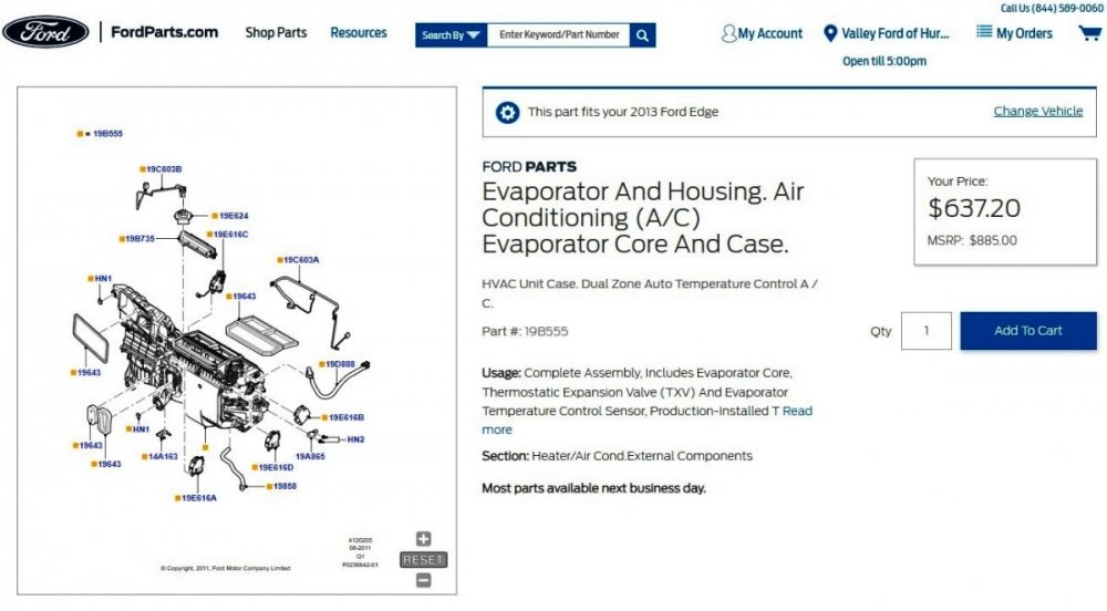

-
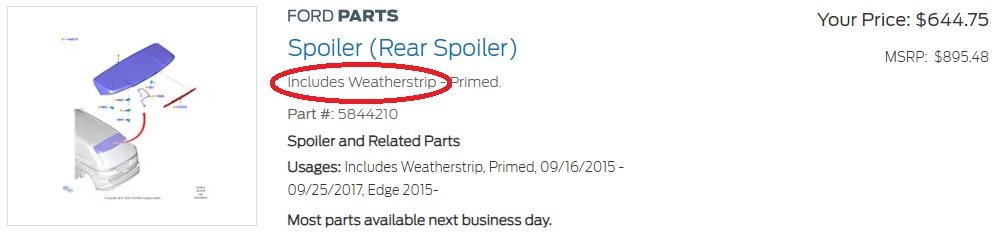
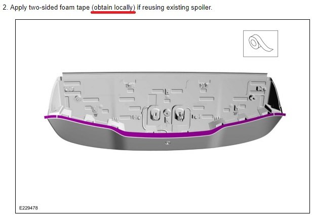
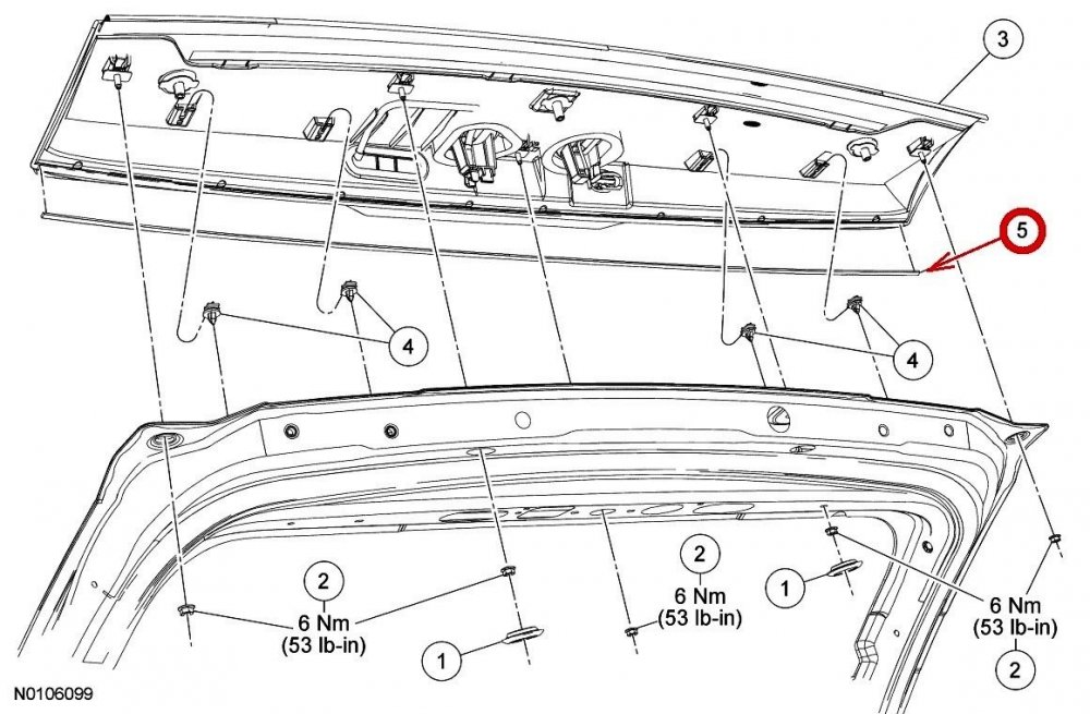
Ford gives you a free Spoiler if you buy this 2017 double-sided tape/weatherstrip... The 2017 Edge Workshop Manual provides this advice on reinstalling a Spoiler... I expect the less elaborate contour of the GEN 1 spoiler causes its separately sold OEM tape/weatherstrip to be shorter than the GEN 2 Spoiler requires, but at slightly over $4 each, I'd be tempted to order-in two GEN 1 tapes and hope for a perfect overlapping splice cut, just to see if it worked out... Good luck!


6-SpeakerWiringDiagram-2022Edge.jpg.44b7898e03db5c8107eff51be9585c28.jpg)

6-SpeakerWiring-InlineConnectorC855-RHB-Pillar-2022Edge.jpg.ab58ff8abe37f353ab3875337b3485bb.jpg)