Haz
-
Posts
1,468 -
Joined
-
Last visited
-
Days Won
393
Everything posted by Haz
-
Additional informational references... Initialization procedure highlights use of drive motor stalling against hard stops rather than mechanical limit switch. Diagnosis and Testing highlights drive motor drive coordination... There is a communication circuit between the shield motor and the sunroof motor for back and fourth communication between the 2 motors only, and not for diagnostics. If the communication circuit between the sunroof motor and shield motor is open or shorted the sunroof motor will operate only to fully close the sliding glass, and the shield motor will not operate at all. Document download links> Power Roof Opening Panel Initialization - General Procedures - 2016 Edge Workshop Manual.pdf Roof Opening Panel - Diagnosis and Testing - 2016 Edge Workshop Manual.pdf Roof Opening Panel Motor - Removal & Installation - 2016 Edge Workshop Manual.pdf Roof Opening Panel Shield - Removal & Installation - 2016 Edge Workshop Manual.pdf Good luck!
-
No immediate answer, though the following resources might assist you toward discovery of a solution... Wiring diagram support is limited, and I expect the Roof Opening Panel Module logic would need to be overcome using jumper wires to enable glass panel movement without a likely shade retraction limit switch being met -- but that's just a guess! Document download links> Roof Opening Panel - System Operation and Component Description - 2016 Edge Workshop Manual.pdf Roof Opening Panel - Component Location - 2016 Edge Workshop Manual.pdf Roof Opening Panel Wiring Diagram - 2016 Edge.pdf Roof Opening Panel Module - Connector C921 Location - 2016 Edge.pdf Overhead Console - Removal & Installation - For Access To Roof Panel Switch Connector - Component Location - 2016 Edge Workshop Manual.pdf Roof Opening Panel Wiring Diagram - Power Distribution - 2016 Edge.pdf Roof Opening Panel Wiring Diagram - Power Distribution 2 - 2016 Edge.pdf Roof Opening Panel Wiring Diagram - Power Grounds - 2016 Edge.pdf Let me know if you get so deep into this that you require Connector Details. Good luck!
-
From the 2008 Edge Workshop Manual... Fluorescent Dye Detection NOTE: Ford Motor Company vehicles are produced with R-134a fluorescent dye installed in the refrigerant system from the factory. The location of leaks can be pinpointed by the bright yellow-green glow of the fluorescent dye under a UV lamp. Since more than one leak can exist, make sure to inspect each component, line and fitting in the refrigerant system for a leak. Good luck!
-
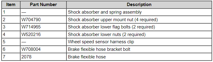
2013 Edge AWD - Front strut torque specs
Haz replied to bimap70455's topic in Brakes, Chassis & Suspension
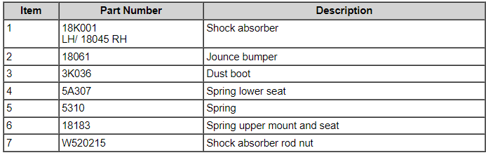
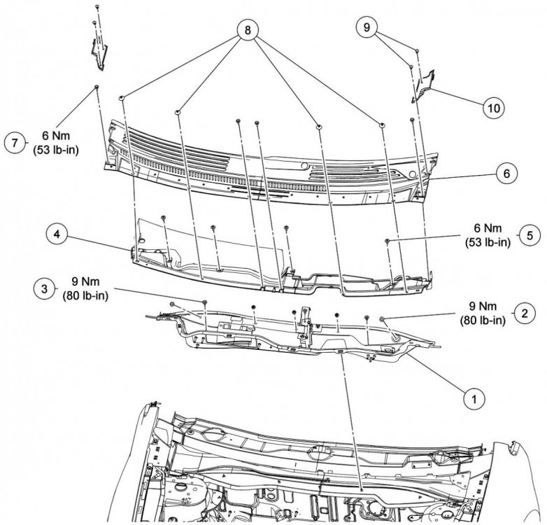
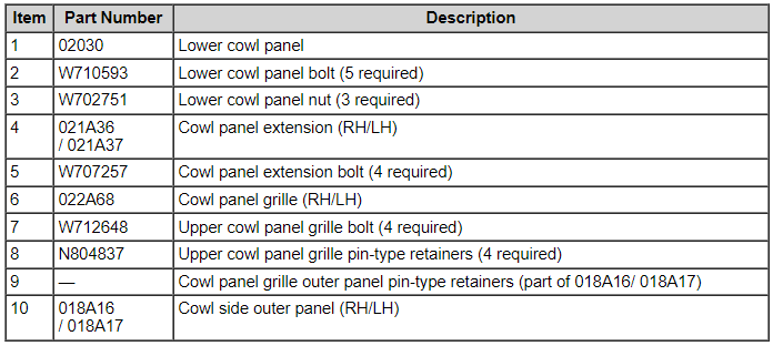
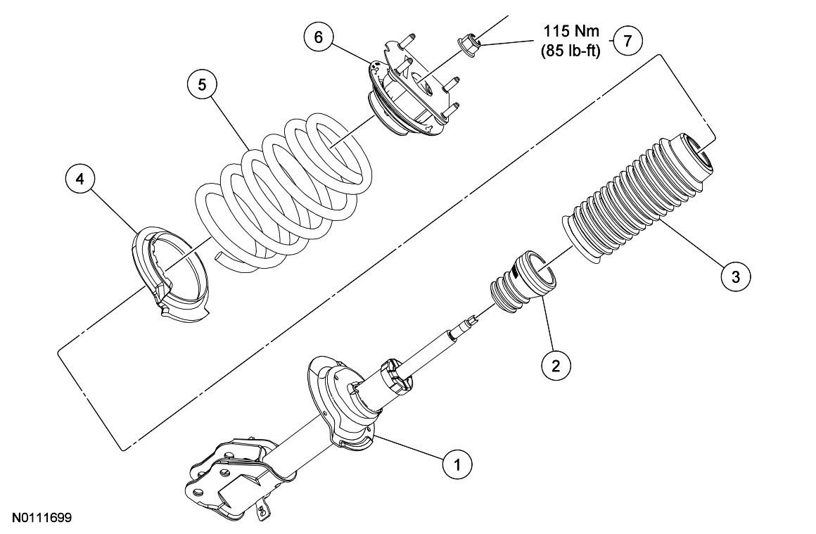
Welcome to the Forum, bimap70455 ! From the 2013 Edge Workshop Manual... Document download links> Front Shock Absorber and Spring Assembly - Removal and Installation - 2013 Edge Workshop Manual.pdf Front Shock Absorber and Spring Assembly - R & I Enhanced Image - 2013 Edge Workshop Manual.pdf Shock Absorber and Spring Assembly - Disassembly & Assembly - 2013 Edge Workshop Manual.pdf Shock Absorber and Spring Assembly - D & A Enhanced Image - 2013 Edge Workshop Manual.pdf Cowl Panel Grille - Removal and Installation - 2013 Edge Workshop Manual.pdf Cowl Panel Grille - R & I Enhanced Image - 2013 Edge Workshop Manual.pdf Good luck!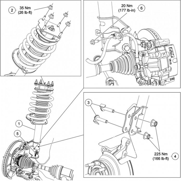

-
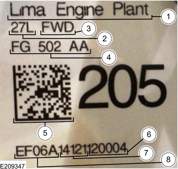
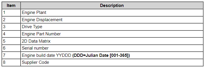
From the 2022 Edge Workshop Manual... Engine Code Information Label The engine code information label, located on the rear of the vacuum pump and on the LH valve cover, contains the following: Item 6/7/8 data is also included as the Engine Trace Serial Number in the OASIS System's Vehicle Information Report, allowing verification of an engine as originally installed. Good luck!
-
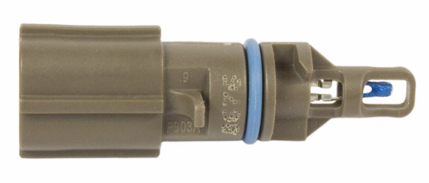
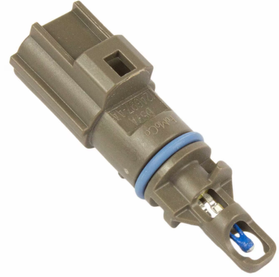
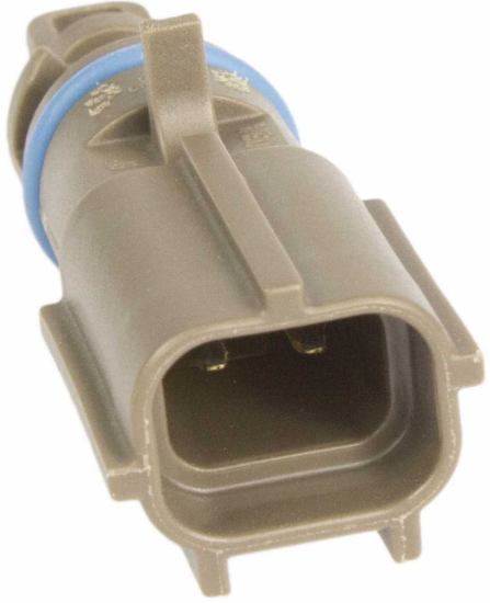
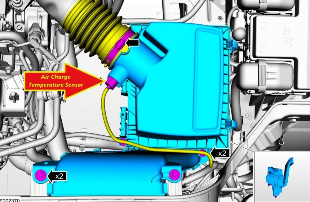
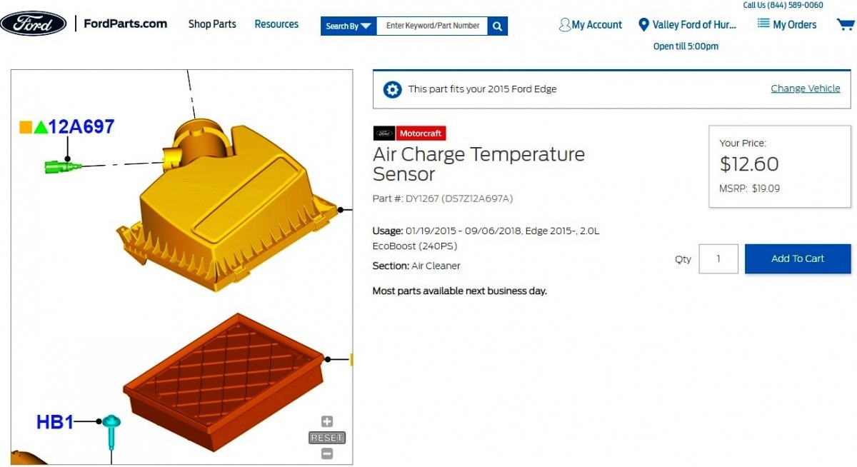
Adding for future reference... Document download link> Manifold Absolute Pressure and Temperature (MAPT) Sensor - Removal and Installation - 2.0L EcoBoost - 2015 Edge Workshop Manual.pdf Good luck!
SensorIllustration-2.0LEcoBoost-2015EdgeWorkshopManual.jpg.e0f52a26cbeba05020266e7af0ef1e15.jpg)
-
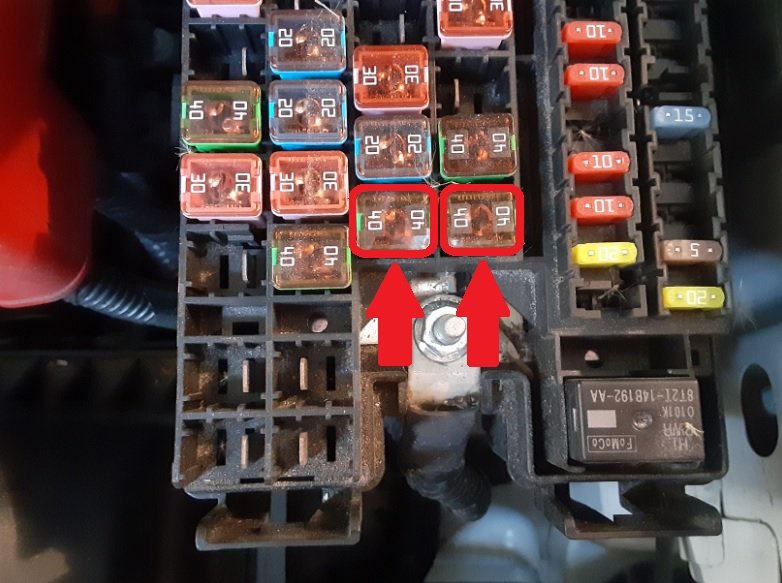
Trailer Tow Package cooling fan power is protected by two 40-amp fuses in the underhood Battery Junction Box (BJB), indicated by red arrows and red outlining in the following photo... Good luck!
-
Manufacturer: Ford Motor Company Products: Model Years 2021-2022 Ford Bronco, Edge, Explorer, and F-150 and Lincoln Aviator and Nautilus vehicles Population: 708,837 (Estimated) Problem Description: Under normal driving conditions without warning the vehicle may experience a loss of motive power without restart due to catastrophic engine failure related to an alleged faulty valve within 2.7 L and 3.0 L EcoBoost Engines Action: Open Engineering Analysis (EA) Document download link> NHTSA - Office of Defects Investigation - Opening of Engineering Analysis (EA) - 09-29-2023.pdf
-
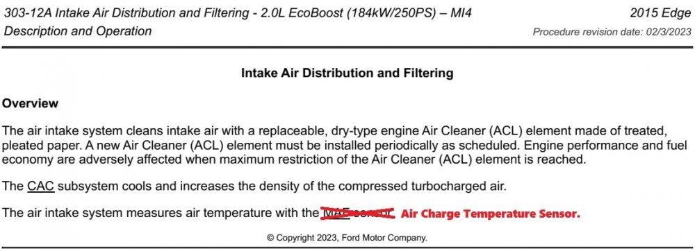
@1004ron: Your skepticism is well-placed and the MAF terminology in the Workshop Manual description is not correct. The 2015 Edge Workshop Manual provides no 2.0L EcoBoost depiction of Mass Air Flow Sensor location, nor any procedures related to it. Additional research on Ford's online parts-selling site yielded no Mass Air Flow Sensor shown as fitting 2015 2.0L EcoBoost, but FordParts does show an Air Charge Temperature Sensor for 2015 & later 2.0L EcoBoost in Edge and many other models... Link to this FordParts web page I have edited the previously posted Workshop Manual section to reflect this newly determined information. Good luck!

-
Good luck!
-
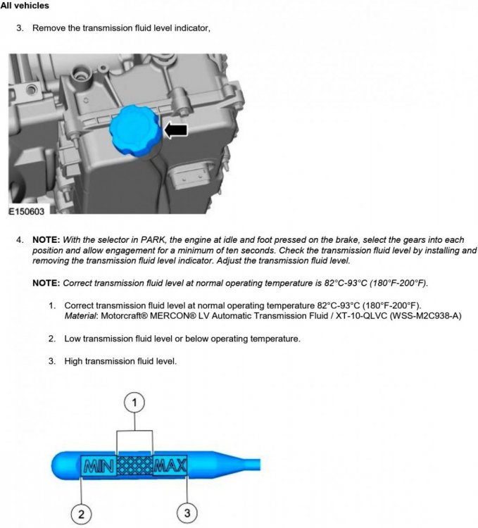
Wipe the entire dipstick dry, insert & withdraw it, view it using an off-angle light source that may highlight the transmission fluid's sheen, and if you're old like me -- reading glasses. Good luck!
-
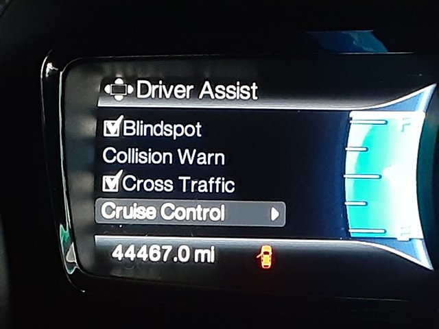
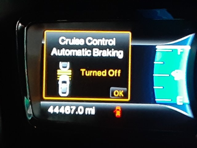
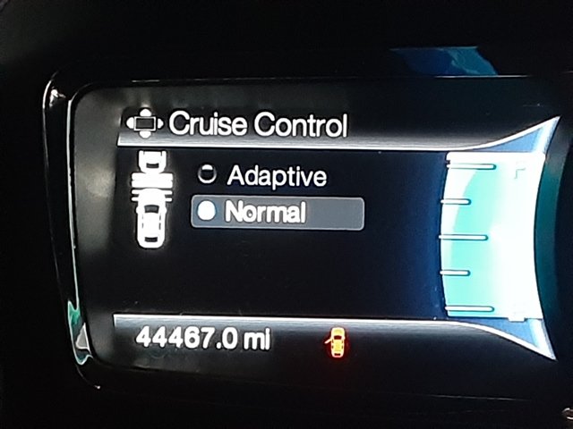
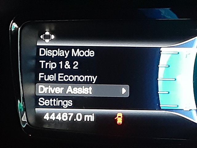
Welcome to the Forum, danwdc ! The following sections from the 2013 Edge Workshop Manual describe the components and operation of the Adaptive Cruise Control & Forward Collision Warning systems, as well as provide extensive diagnostic procedures guided by Diagnostic Trouble Codes (DTCs) and using Parameter Identifiers (PIDs), in most cases. If your efforts progress to applying specific Pinpoint Test routines requiring wiring diagrams and electrical connector circuit details and locations, I can provide you those informational resources. Document download links> Cruise Control — Adaptive - Description and Operation - 2013 Edge-MKX Workshop Manual.pdf Cruise-Control Module (C-CM) - Removal and Installation - 2013 Edge-MKX Workshop Manual.pdf Cruise Control Module (C-CM) (with Sensor) Adjustment - General Procedures - 2013 Edge-MKX Workshop Manual.pdf Cruise Control - Diagnosis and Testing - 2013 Edge-MKX Workshop Manual.pdf Forward Collision Warning - Description and Operation - 2013 Edge-MKX Workshop Manual.pdf Forward Collision Warning - Diagnosis and Testing - 2013 Edge-MKX Workshop Manual.pdf For comparison to your 2013 Edge's left-side Information Screen, the following photos show the menu structure in our similarly equipped (and also GEN 1+) 2015 MKX... After Normal is selected, the following Warning Message appears, accompanied by a Warning Chime... Good luck!

-
From the 2016 Edge Workshop Manual, relating to the 6F50 6-Speed Auto Trans paired with the 3.5L Duratec (or the 6F55 paired with the 2.7L EcoBoost)... NOTE: If the transmission was removed and disassembled, fill the transmission with 6.2L (6.5 qt) of clean transmission fluid. If the main control cover was removed, fill the transmission with 4.3L (4.5 qt) of clean transmission fluid. Material: Motorcraft® MERCON® LV Automatic Transmission Fluid / XT-10-QLVC (WSS-M2C938-A) Document download links> Transmission Fluid Drain and Refill - 6F50-6F55 6-Speed Auto Trans - 2016 Edge Workshop Manual.pdf Transmission Fluid Level Check - 6F50-6F55 6-Speed Auto Trans - 2016 Edge Workshop Manual.pdf Good luck!
-
The following sections from the 2016 Edge Workshop Manual describe the components and operation of the AWD system, as well as provide extensive diagnostic procedures guided by Diagnostic Trouble Codes (DTCs), in most cases. If your efforts progress to applying specific Pinpoint Test routines requiring wiring diagrams and electrical connector circuit details and locations, I can provide you those informational resources. Document download links> Four-Wheel Drive Systems - System Operation and Component Description - 2016 Edge Workshop Manual.pdf Transfer Case 3.5L Duratec - Power Transfer Unit (PTU) Overview - 2016 Edge Workshop Manual.pdf Transfer Case 3.5L Duratec - Transfer Case Cooler - Removal and Installation - 2016 Edge Workshop Manual.pdf Transfer Case - Diagnosis and Testing - 2016 Edge Workshop Manual.pdf Four-Wheel Drive Systems - Active Torque Coupling Configuration - 2016 Edge Workshop Manual.pdf Four-Wheel Drive Systems - Diagnosis and Testing - 2016 Edge Workshop Manual.pdf All Wheel Drive (AWD) Module - Removal and Installation - 2016 Edge Workshop Manual.pdf Good luck!
-
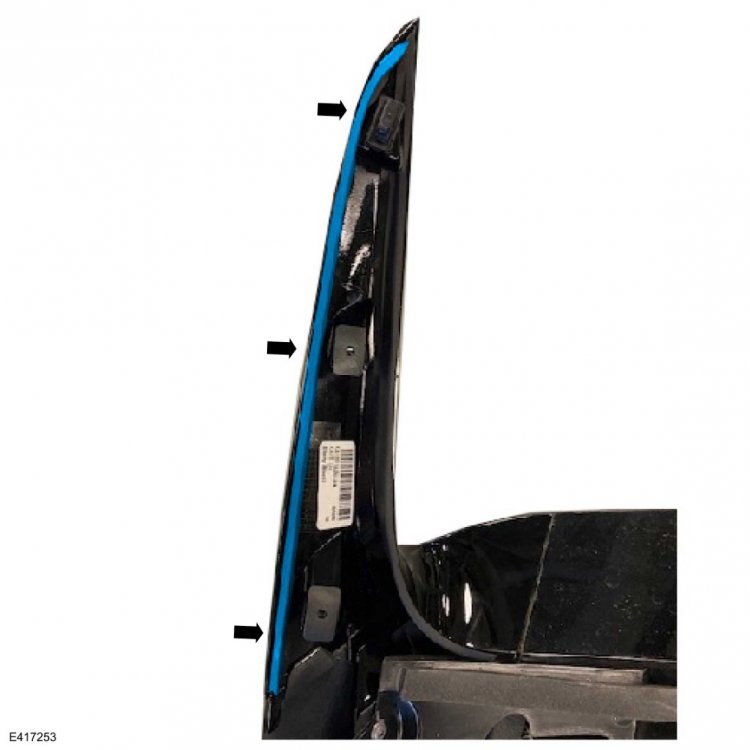
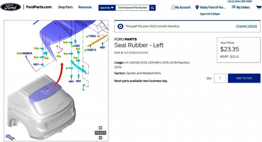
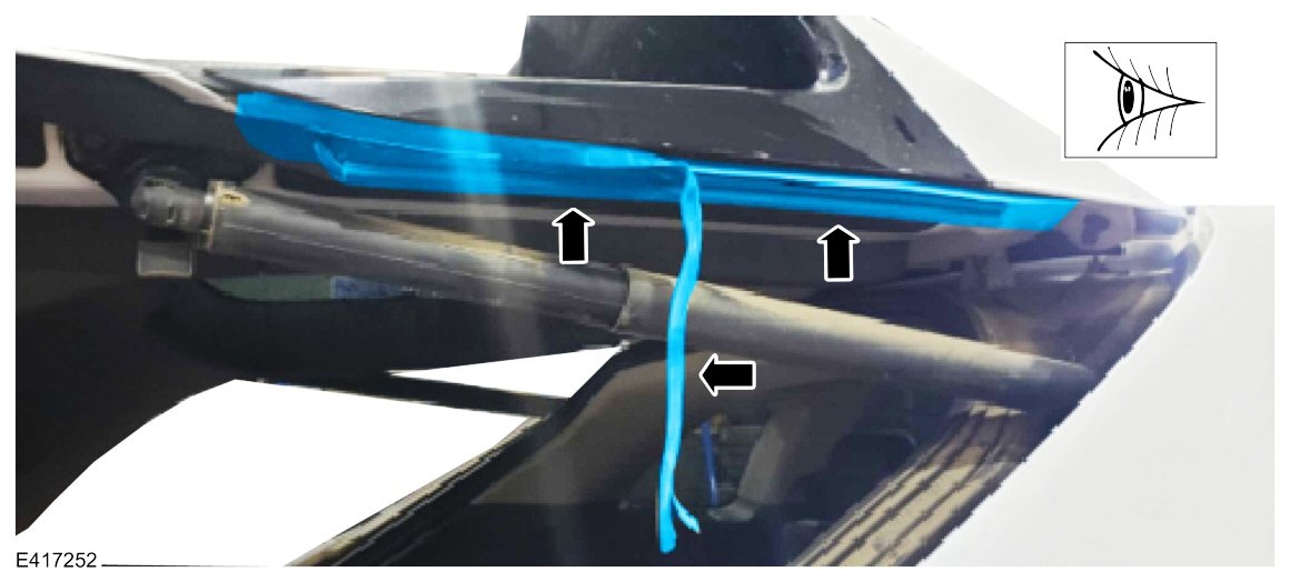
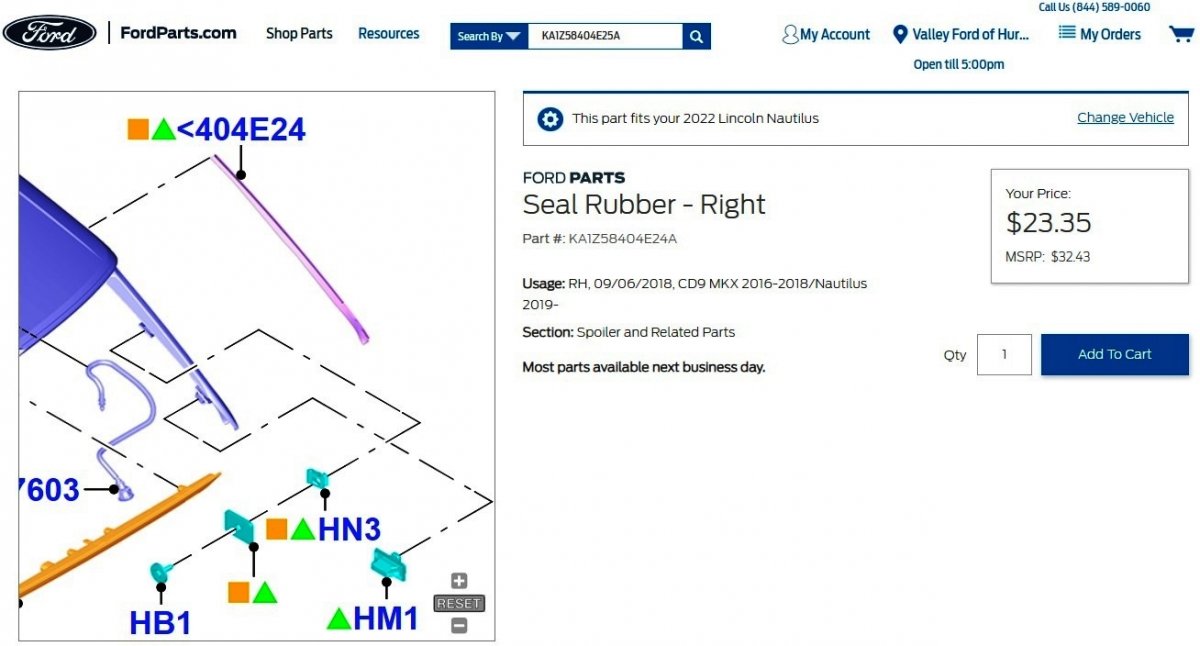
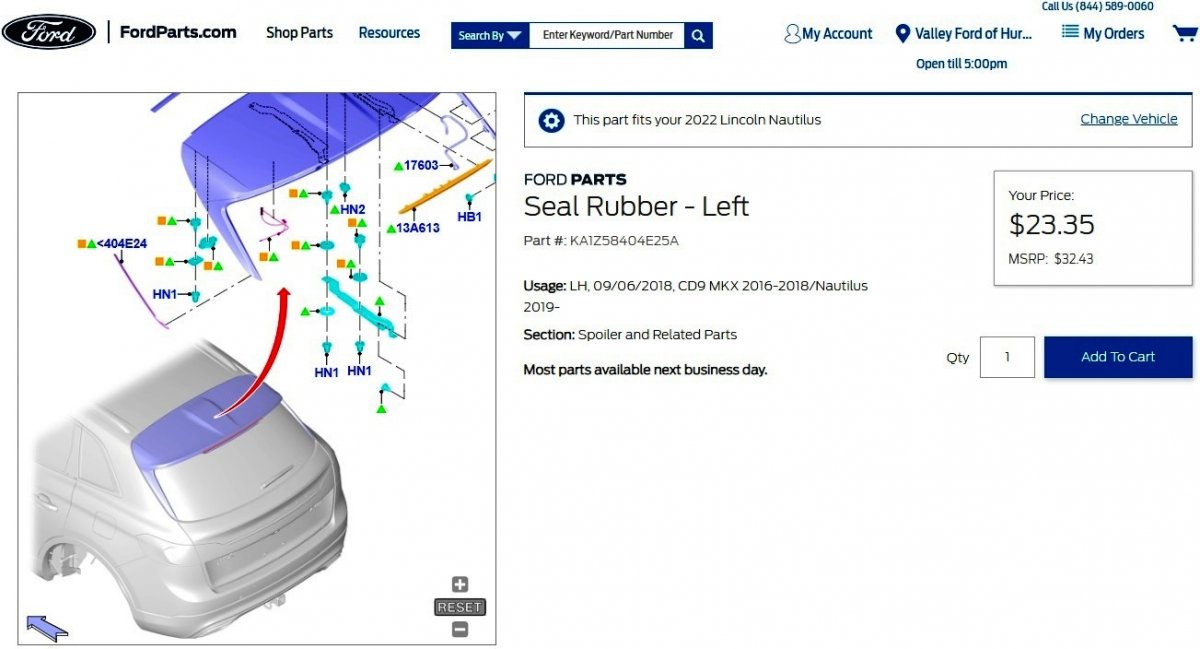
TECHNICAL SERVICE BULLETIN Rubber Seal Loose Between Spoiler Support And Liftgate 23-2237 27 September 2023 Model: Lincoln 2019-2022 Nautilus Issue: Some 2019-2022 Nautilus vehicles may exhibit the rubber seal between the spoiler support and the liftgate coming loose as shown in Figure 1. This may be due to poor adhesion between the spoiler and the rubber seal. To correct the condition, follow the Service Procedure to replace spoiler support rubber seal. Action: Follow the Service Procedure to correct the condition on vehicles that meet the following criteria: • 2019-2022 Nautilus • Loose rubber seal between the spoiler support and the liftgate as shown in Figure 1 Parts Service Part Number Quantity Description Unit of Issue Piece Quantity KA1Z-58404E24-A 1 Right Rubber Seal 1 1 KA1Z-58404E25-A 1 Left Rubber Seal 1 1 Obtain Locally As Needed Isopropyl Alcohol Quantity refers to the amount of the service part number required to repair the vehicle. Unit of Issue refers to the number of individual pieces included in a service part number package. Piece Quantity refers to the total number of individual pieces required to repair the vehicle. As Needed indicates the amount of the part may vary and/or is not a whole number. Parts can be billed out as non-whole numbers, including less than 1. Warranty Status: Eligible under provisions of New Vehicle Limited Warranty (NVLW)/Service Part Warranty (SPW)/Special Service Part (SSP)/Extended Service Plan (ESP) coverage. Limits/policies/prior approvals are not altered by a TSB. NVLW/SPW/SSP/ESP coverage limits are determined by the identified causal part and verified using the OASIS part coverage tool. Labor Times Description Operation No. Time 2019-2022 Nautilus: Replace The Spoiler Support Rubber Seal (Do Not Use With Any Other Labor Operations) 232237A 0.9 Hrs. Repair/Claim Coding Causal Part: 5844210 Condition Code: 33 Service Procedure Figure 1 1. Remove the spoiler. Refer to Workshop Manual (WSM), Section 501-08 - Exterior Trim and Ornamentation - Removal and Installation - Rear Spoiler. 2. Remove the loose spoiler support rubber seal. (Figure 2) Figure 2 3. Clean the surface with isopropyl alcohol. 4. Align and attach the new rubber seal. 5. Install the spoiler. Refer to WSM, Section 501-08 - Exterior Trim and Ornamentation - Removal and Installation - Rear Spoiler. © 2023 Ford Motor Company All rights reserved. NOTE: The information in Technical Service Bulletins is intended for use by trained, professional technicians with the knowledge, tools, and equipment to do the job properly and safely. It informs these technicians of conditions that may occur on some vehicles, or provides information that could assist in proper vehicle service. The procedures should not be performed by "do-it-yourselfers". Do not assume that a condition described affects your car or truck. Contact a Ford or Lincoln dealership to determine whether the Bulletin applies to your vehicle. Warranty Policy and Extended Service Plan documentation determine Warranty and/or Extended Service Plan coverage unless stated otherwise in the TSB article. The information in this Technical Service Bulletin (TSB) was current at the time of printing. Ford Motor Company reserves the right to supersede this information with updates. The most recent information is available through Ford Motor Company's on-line technical resources. Document download links to resources mentioned in TSB 23-2237> TSB 23-2237 - 2019-2022 Nautilus - Rubber Seal Loose Between Spoiler Support And Liftgate - 09-27-2023.pdf TSB 23-2237 - 2019-2022 Nautilus - Enhanced Image - Figure 1.pdf TSB 23-2237 - 2019-2022 Nautilus - Enhanced Image - Figure 2.pdf Rear Spoiler - Removal and Installation - 2022 Nautilus Workshop Manual.pdf Link to this page from Ford's online parts website Link to this page from Ford's online parts website


-
2007-2015 Edge, MKX low brake pedal simple fix
Haz replied to enigma-2's topic in Brakes, Chassis & Suspension
Additional info from the Edge Workshop Manual, with emphasis added... Brake Master Cylinder Compensator Ports The purpose of the compensator ports in the brake master cylinder is to supply additional brake fluid from the master cylinder reservoir when needed by the brake system due to brake lining wear and allow brake fluid to return to the master cylinder reservoir when the brakes are released. The returning brake fluid creates a slight turbulence in the master cylinder reservoir. This is a normal condition and indicates that the compensator ports are not clogged. Clogged compensator ports may cause the brakes to hang up or not fully release. Document download link> Brake System - Principles of Operation - 2014 Edge Workshop Manual.pdf Good luck! -
Power Folding Mirror Synchronization Video #2 Power Folding Mirror Synchronization Video #2.mp4
- 1 reply
-
- 1
-

-
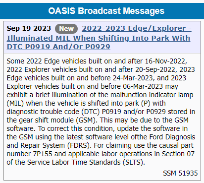
Special Service Message 51937 - Various 2015-2023 Vehicles - Inoperative Or Clicking Sound From Power Folding Exterior Mirrors Some vehicles equipped with power folding mirrors may exhibit power folding mirrors that are inoperative or exhibit a clicking sound. This may be due to the mirrors being manually folded in, during transportation, going through a car wash, bumped in a parking lot, or found during pre-delivery inspection (PDI). Prior to the replacement of any components, attempt to synchronize the mirrors by following the Power Mirrors Synchronization procedure. Refer to Workshop Manual (WSM)Section 501-09 Rear View Mirrors - General Procedures - Power Mirrors Synchronization. Power Folding Mirror Synchronization Video #1 Power Folding Mirror Synchronization Video #1.mp4
- 1 reply
-
- 1
-
-
Windshield wiper fluid reveresed
Haz replied to BmbSqd's topic in Glass, Lenses, Lighting, Mirrors, Sunroof (BAMR), Wipers
Additional document download links> WINDSHIELD WASHER PUMP - Wiring Diagram - 2019 Edge.pdf Rear Window Wiper Motor - Wiring Diagram - 2019 Edge.pdf Windshield Wiper Motors - Wiring Diagram - 2019 Edge.pdf Wiper Motors & Washer Pump - Power Distribution Wiring Diagram - 2019 Edge.pdf WINDSHIELD WASHER PUMP - Connector C137 Details - 2019 Edge.pdf WINDSHIELD WASHER PUMP - Connector C137 Location - 2019 Edge.pdf WINDSHIELD WIPER MOTOR LH - Connector C1665 Details - 2019 Edge.pdf Windshield Wiper Motor - Removal and Installation - 2019 Edge Workshop Manual.pdf Cowl Panel - Removal and Installation - 2019 Edge Workshop Manual.pdf Cowl Panel Grille - Removal and Installation - 2019 Edge Workshop Manual.pdf Windshield Wiper Pivot Arm - Removal and Installation - 2019 Edge Workshop Manual.pdf BATTERY JUNCTION BOX (BJB) - Connector C1035B Details - 2019 Edge.pdf BATTERY JUNCTION BOX (BJB) - Connector C1035B Location - 2019 Edge.pdf BATTERY JUNCTION BOX (BJB) Illustration- Shows Connector C1035B Receptacle Location - 2019 Edge.pdf Link to this FordParts web page Titanium Plus packaged Edges with the front camera washer use the following washer pump... Link to this FordParts web page The above FordParts web pages include numerous photos of the described washer pumps. Good luck!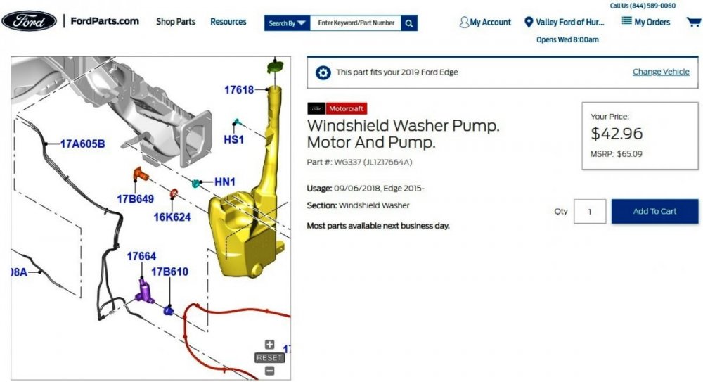
-FordParts.thumb.jpg.ca3dff6490d4e487e562c4dbd06a216a.jpg)
- 2 replies
-
- 1
-
-
- fluid
- windshield
- (and 1 more)
-
Windshield wiper fluid reveresed
Haz replied to BmbSqd's topic in Glass, Lenses, Lighting, Mirrors, Sunroof (BAMR), Wipers
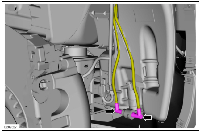
Welcome to the Forum, BmbSqd ! Your Edge's washer pump is attached to the lower portion of the washer fluid reservoir in the forward passenger side corner of the engine compartment... ghlighted You'll notice the two yellow-highlighted washer fluid hoses with their pink-highlighted couplings attached to the washer pump outlets. I expect one hose supplies the windshield nozzles and the other hose supplies the rear window nozzle, per these technical descriptions of front & rear washer operation from the 2019 Edge Workshop Manual... Windshield Washer When the wiper/washer switch is activated, the SCCM sends the washer request to the driver side windshield wiper motor assembly over the LIN . The windshield wash relay is internal to the driver side windshield wiper motor assembly. When the driver side windshield wiper motor assembly activates the internal windshield wash relay, voltage is provided to the washer pump, directing washer fluid to the windshield. If equipped with a front camera, washer solvent is also directed to the front camera lens when the washer pump is active. When the switch is released, the windshield wiper motors will continue to activate for 3 additional wipes and then turn off. Ground for the washer pump is provided through the rear window washer relay located within the BJB . Rear Window Washer When the rear window washer switch is activated, the SCCM sends the request to the driver side windshield wiper motor assembly through the LIN . The driver side windshield wiper motor assembly energizes the rear washer relay (located in the BJB ) and activates the rear window wiper motor. When the driver side windshield wiper motor assembly activates the rear window wash relay, voltage is provided to the washer pump, directing washer fluid to the rear window. When the switch is released, the rear window wiper motor continues to operate for 3 additional wipes and then turns off. Ground for the washer pump is provided through the windshield washer relay within the driver side windshield wiper motor assembly. Presuming the washer fluid hose couplings are not fool-proofed to only connect to the appropriate washer pump outlet for front or rear nozzle, then your swapping the hoses side-to-side may correct your Edge wrong-way spraying issue. Given that you've recently purchased the Edge, it seems unlikely a non-working washer pump was replaced and the wrong-way spray issue went unnoticed, though maybe it was a hurried job. It may be the result of a washer pump malfunction or a wiring/switch issue, but if swapping the hoses produces interim improvement, then it's worth a try. I've pulled relevant sections from the 2019 Edge Workshop and Wiring manuals, which will likely require two posts to provide due to Forum attachment size limitations. Document download links> Wipers and Washers - System Operation and Component Description - 2019 Edge Workshop Manual.pdf Windshield Washer Pump - Removal and Installation - 2019 Edge Workshop Manual.pdf Fender Splash Shield - Removal and Installation - 2019 Edge Workshop Manual.pdf Washer Hose Coupling - General Procedures - 2019 Edge Workshop Manual.pdf Windshield Washer Reservoir - Removal and Installation - 2019 Edge Workshop Manual.pdf Wipers and Washers - Diagnosis and Testing - 2019 Edge Workshop Manual.pdf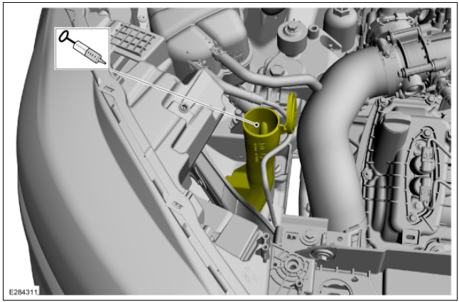
- 2 replies
-
- 1
-
-
- fluid
- windshield
- (and 1 more)
-
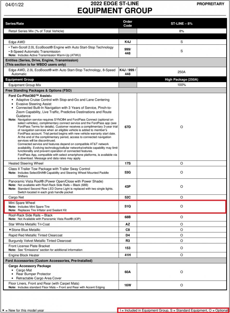
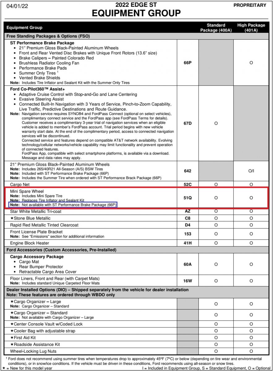
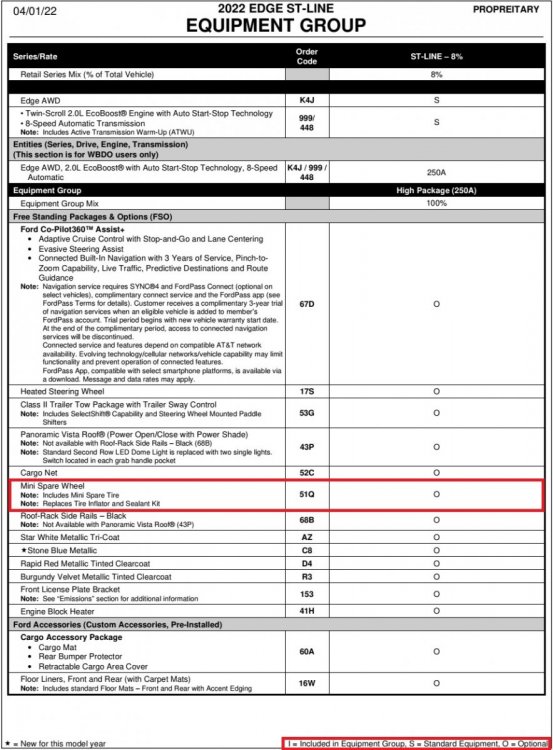
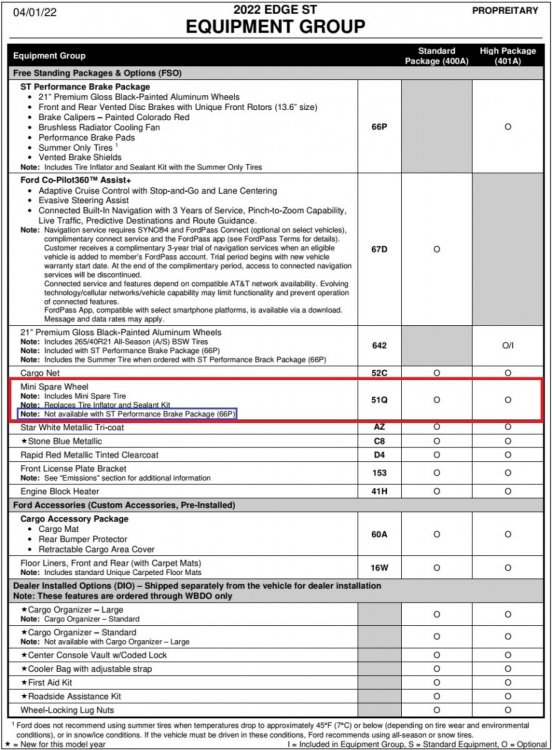
Welcome to the Forum, Gunner3.5 ! The 2022 Edge Order Guide shows the Mini Spare as optional equipment on the ST-Line... ...The Order Guide also shows the Mini Spare as optional on ST, but as Davidoo states, unavailable with the ST Performance Brake Package... Good luck!
-
Splash shield for 2.0 interchangeable with 3.5L?
Haz replied to Oranga's topic in Brakes, Chassis & Suspension
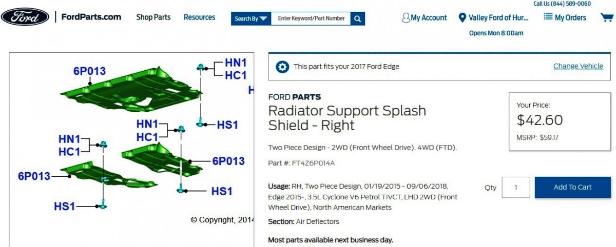
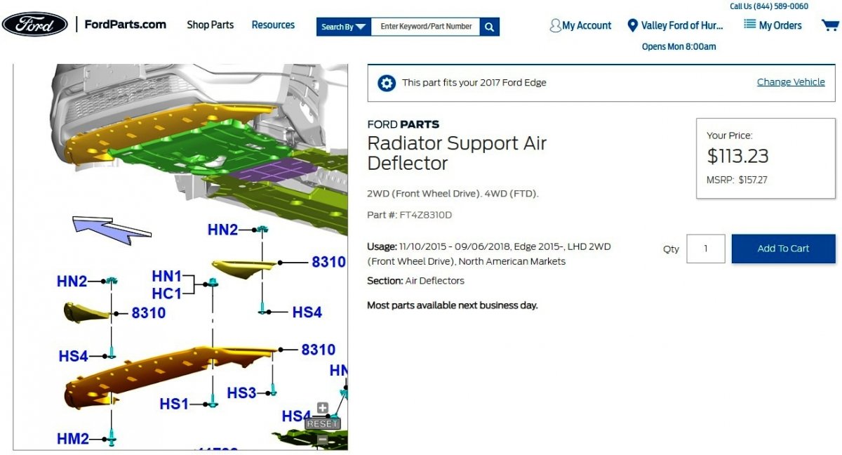
Ford's online parts-selling site shows a 2-piece design Splash Shield for the 2017 3.5L Edge... Link to this web page Link to this web page ...Unless it is the Front Air Deflector you are seeking... Link to this web page The above-linked FordParts web pages include multiple photos of each described part. Good luck!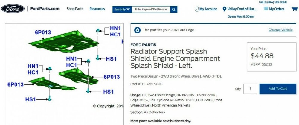


-
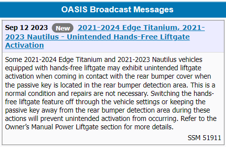
Ford is restating to the Service community that unintended hands-free liftgate operation is normal and no repair is needed to eliminate it, but that the solution for affected vehicle owners is deactivating the power liftgate or not having the passive key fob near the rear bumper when active in the cargo load space ... Good luck!


09-20-2023.jpg.406d8706ab9b3a07deea68866dea06bb.jpg)
09-20-2023.jpg.59992e494154935b500c3899d0d1bff7.jpg)
09-20-2023.jpg.970dae23a71887cca97686bcef0a54ac.jpg)

-FordParts.jpg.9b4051decec51f4ab6b39fbd14b6b2d6.jpg)