

Haz
-
Posts
1,251 -
Joined
-
Last visited
-
Days Won
325
Content Type
Profiles
Forums
Gallery
Everything posted by Haz
-
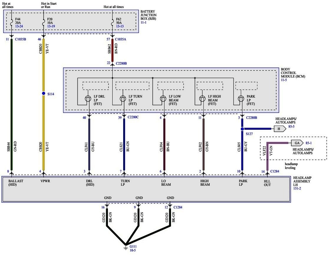
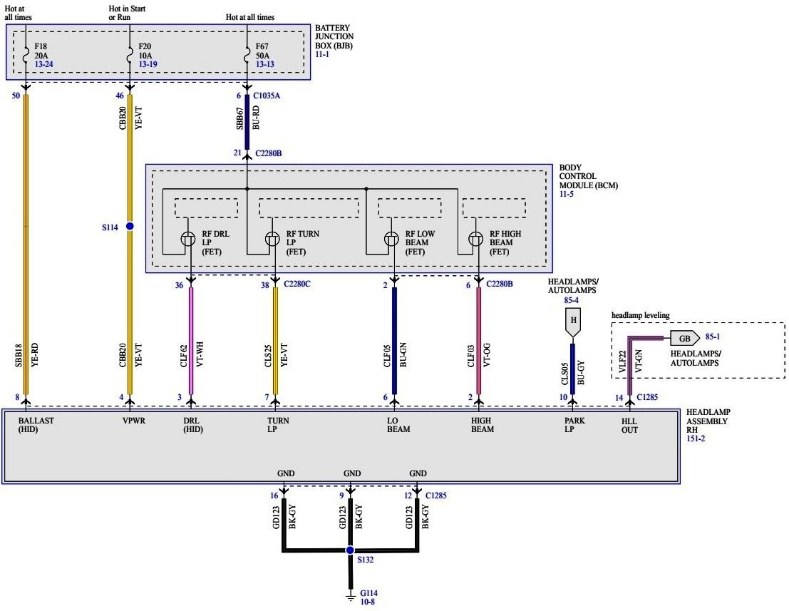
From the 2016 Edge Workshop Manual... Moving your device cursor over capitalized acronyms should yield an onscreen full-word description. DRL System Diagram Network Message Chart BCM Network Input Messages Broadcast Message Originating Module Message Purpose Gear position PCM Indicates the GSM request to the BCM . When the GSM has selected any position other than park, the BCM activates the DRL . DRL For the halogen headlamp system, the DRL system utilizes the existing circuitry and components from the headlamp low beam system. The DRL system operates the low beam headlamps at a reduced intensity. For the High Intensity Discharge (HID) headlamp system, DRL system utilizes a halogen bulb in the headlamp assembly. The BCM monitors the ignition status, the headlamp switch and autolamp status. There are two types of DRL . Conventional (where it is required) and configurable. When equipped with conventional DRL , the DRL are active in any headlamp switch position except the HEADLAMPS position. When equipped with configurable DRL , the DRL may be enabled through the IPC message center. When enabled, the DRL are active only in the AUTOLAMPS headlamp position. When autolamps request the headlamps on, the DRL are de-activated. The DRL are activated when the following conditions are met: the ignition is in run the headlamps have not been turned on by the autolamp system or the headlamp switch the transmission is not in park When a turn signal is active, the corresponding daytime running lamp will turn off. Once the turn signal is deactivated, the daytime running lamp returns to normal operation. When the transmission is in not in PARK, the PCM sends a message over the HS-CAN1 to the BCM indicating the transmission is not in PARK. The BCM also provides Field Effect Transistor (FET) protection of the exterior lamps switched voltage and DRL output circuits. When an excessive current draw is detected, the BCM disables the affected circuit driver. Field Effect Transistor (FET) Protection The BCM utilizes an Field Effect Transistor (FET) protective circuit strategy for many of its outputs, for example, lamp output circuits. Output loads (current level) are monitored for excessive current (typically short circuits) and are shut down (turns off the voltage or ground provided by the module) when a fault event is detected. A Field Effect Transistor (FET) is a type of transistor that the control module software uses to control and monitor current flow on module outputs. The Field Effect Transistor (FET) protection strategy prevents module damage in the event of excessive current flow. Output loads (current level) are monitored for excessive current draw (typically short circuits). When a fault event is detected the Field Effect Transistor (FET) turns off and a short circuit DTC sets. The module resets the Field Effect Transistor (FET) protection and allows the circuit to function when the fault is corrected or the ignition state is cycled off and then back on. When the excessive circuit load occurs often enough, the module shuts down the output until a repair procedure is carried out. Each Field Effect Transistor (FET) protected circuit has 3 predefined levels of short circuit tolerance based on a module lifetime level of fault events based upon the durability of the Field Effect Transistor (FET). If the total tolerance level is determined to be 600 fault events, the 3 predefined levels would be 200, 400 and 600 fault events. When each level is reached, the DTC associated with the short circuit sets along with DTC U1000:00. These Diagnostic Trouble Codes (DTCs) can be cleared using the module on-demand self-test, then the Clear DTC operation on the scan tool (if the on-demand test shows the fault corrected). The module never resets the fault event counter to zero and continues to advance the fault event counter as short circuit fault events occur. If the number of short circuit fault events reach the third level, then Diagnostic Trouble Codes (DTCs) U1000:00 and U3000:49 set along with the associated short circuit DTC . DTC U3000:49 cannot be cleared and the module must be replaced after the repair. Headlamp Assembly Wiring Diagram - Left Hand Headlamp Assembly Wiring Diagram - Right Hand Good luck!


-
Welcome to the Forum! Power fold/auto fold outside mirrors were offered initially on the MKX for 2016 model year, and later on the Edge for 2020 model year. Good luck!
-
While this General Service Bulletin is written for 2019-2023 Ranger models, it's technique of using a tape measure and masking tape on the steering wheel to measure brake pedal travel does provide a measurement that may be useful when describing brake performance issues to a Dealership Service Rep or Professional Service Technician... GENERAL SERVICE BULLETIN Brake Pedal Travel Measurement Procedure 23-7030 02 March 2023 This bulletin supersedes 22-7059. Model: Ford 2019-2023 Ranger Summary This article supersedes GSB 22-7059 to update the vehicle model years affected. This article is to assist with determining when brake system repairs are necessary to address the symptom of excessive brake pedal travel (low/spongy pedal). Brake Pedal Travel Measurement Procedure 1. With the vehicle on a flat surface, place the transmission selector level in park (P). Do not apply the parking brake. 2. With the engine off, push the brake pedal heavily 10 times. This will remove all vacuum from the brake booster. 3. Pedal travel measurement set up: (1). The steering wheel position will need to be: • Straight/centered with the lower opening at the 6 o’clock position. • Up/down (tilt) position is to be at its lowest point. • In/out (telescoping) position should be at its most inward position (toward the brake pedal). (2). Wrap a 2 inch (5 cm) wide strip of low-tac tape through the lower opening of the steering wheel. (3). Extend a tape measure (in centimeters if available) through the lower opening of the steering wheel over the tape that was just installed. Use caution to prevent any damage to the steering wheel. (Figure 1) Figure 1 (4). Secure the end of the tape measure to the left/center side of the brake pedal as shown. A high-tac tape can be used to hold the end of the tape measure in place during the procedure. (Figure 2) Figure 2 (5). Using a ball point pen, draw a line on the tape to create an indicating mark for the tape measure. (Figure 3) Figure 3 (6). The brake pedal travel measurement set up at the steering wheel should look like this. The actual measurement shown below is only an example and should not be used when calculating pedal travel on the vehicle being tested. (Figure 4) Figure 4 4. Ford Diagnosis and Repair System (FDRS) setup: (1). Connect the FDRS to the vehicle and begin a vehicle session. (2). In the FDRS Menu, access User Settings and make sure that the unit of measure for Pressure is set to kPa. (3). Select the toolbox tab and then datalogger from the list on the right side of the screen. (4). On the datalogger module selection screen, select Anti-lock Brake System (ABS) module and Continue. (5). On the parameter identification (PID) list selection screen for the ABS module, select: BRKHYDPRESS. 5. Brake pedal travel measurement: (1). With the brake pedal not-pressed, record the reading of the tape measure at the line draw on the tape on the steering wheel. (Figure 4) (2). While monitoring the BRKHYDPRESS PID in FDRS, slowly press the brake pedal until 1000 kPa is obtained. (3). Record the reading of the tape measure at the line drawn on the tape on the steering wheel while the brake pedal pressure is being held at 1000 kPa. (4). Perform this test a total of 5 times with 30 second intervals after each press of the brake pedal. Document all readings in the chart provided below. (Table 1) Table 1 Test Number Brake Pedal Not Pressed Measurement (cm) Brake Pedal Pressed Measurement (cm) Calculated Brake Pedal Travel (cm) 1 2 3 4 5 Brake pedal travel average: 6. Is the average brake pedal travel equal to or less than 5.2 cm? (1). Yes - brake pedal travel is within normal range and the brake hydraulic system is operating normally. (2). No - perform a Brake System Pressure Bleeding, refer to Workshop Manual (WSM), Section 206-00 and retest. If the average brake pedal travel is still above the normal range after performing the Brake System Pressure Bleeding procedure, refer to WSM, Section 206-00 for further diagnosis and testing. © 2023 Ford Motor Company All rights reserved. NOTE: This information is not intended to replace or supersede any warranty, parts and service policy, workshop manual (WSM) procedures or technical training or wiring diagram information.
-
GENERAL SERVICE BULLETIN Adaptive Cruise, Pre-Collision And Collision Avoidance System Functionality Diagnostics 23-7031 02 March 2023 This bulletin supersedes 22-7034. Summary This article supersedes GSB 22-7034 to update the Service Information and vehicle model years affected. This article is intended to aid in the diagnosis for vehicles with difficulty resolving image processing module A (IPMA) or cruise control module (CCM) alignment and/or functionality concerns. Service Information Adaptive cruise control and collision avoidance systems can use a forward windshield camera only IPMA or a combination of IPMA and a CCM. Make sure which system is present on the vehicle so the system evaluation is completed properly. The forward collision system warning indicator will be illuminated when the vehicle is in transport mode. Prior to any diagnosis, be sure the vehicle is not in transport mode. For further information on transport mode, Refer to Workshop Manual (WSM), Section 419-10. NOTE: Follow the Service Procedures to troubleshoot IPMA and CCM alignment issues before replacing the parts. For Mustang Mach-E and F-150 vehicles equipped with base part number 14G647, alignment and blockage issues are specific to the sensors and not the electronic control unit (ECU). IPMA (near rear view mirror) forward windshield camera (Figure 1) Figure 1 CCM (in the front grille, either visible or behind bumper) RADAR sensor (Figure 2) Figure 2 NOTE: Environmental factors such as sun position, glare, moisture, frost, snow, ice, and dust/dirt can interfere with system vision and may cause the system to become inactive with a warning until these items clear. If the IMPA/CCM alignment procedure is not successful, inspect for the presence of outside factors. Possible outside factors that may affect IPMA alignment 1. Diagnostic trouble codes (DTCs) other than C1001:54, C1001:78, C1001:97 present in IPMA or other modules (1). Repair all other DTCs prior to diagnosing or attempting IPMA alignment 2. Unclear road markings 3. Module or circuit concerns 4. Accessories blocking camera view, including but not limited to: (1). Snow plow (2). Winch (3). Bug guard 5. Vehicle ride height - refer to specifications in Workshop Manual (WSM), Section 204-00 (1). Vehicle squatting from cargo weight (2). Lift kit (3). Lowering kit (4). Leveling kit (5). Incorrect tire size (6). Other modifications that affect vehicle ride height or stance (7). Incorrect wheel arch measurements input in Interactive Diagnostic System (IDS)/Ford Diagnosis and Repair System (FDRS) 6. Inspect windshield (1). If this concern began after a recent windshield replacement, inspect the replacement windshield for imperfections and correct installation (2). Aftermarket windshield installed • Carlite replacement windshield recommended (3). Windshield clean of moisture, snow, ice, frost, and dust/dirt (4). IPMA lens clean (5). Aftermarket tinting or windshield banners/stickers (6). Glass distortion can distort the camera’s view and prevent camera alignment and functionality (Figure 3) Figure 3 (7). IPMA mounting and/or bracket off-center, not clocked properly or not secured to windshield (Figures 4-5) Figure 4 Figure 5 (8). Windshield not installed correctly. Figure 6 shows a windshield that is recessed near the vehicle’s roof, causing the camera to be pitched upward. Figure 6 Possible outside factors that may affect CCM alignment 1. DTCs present in CCM or other modules Repair all DTCs prior to diagnosing or attempting CCM alignment 2. Module or circuit concerns (usually DTCs would be present) 3. CCM radar blocked - may result in CCM DTC C1A67:97 Figure 7 Inspect the front bumper or CCM location for snow, ice, dust/dirt (Figure 7) (1). Incorrect front license plate/bracket mounting (2). Aftermarket or incorrect bumper or grille (3). Brush guard installed (4). Snow plow or snow plow mounting hardware installed (5). Other aftermarket accessories installed on front of vehicle (Figure ? Figure 8 (6). CCM mounting hardware bent or damaged or improper CCM mounting (Figure 9) NOTE: Improper CCM mounting may also result in DTCs B142E:78 or B1432:78 in the CCM Figure 9 (7). Facia damaged, facia installed incorrectly, or aftermarket facia installed. 4. Using the FDRS tool, check the parameter identification (PID) for ALGN_OFF -CCM. A value greater than +/-3 degrees indicates a mounting issue with the CCM, not necessarily a defective module. Check for CCM or mounting surface damage. If found repair damage as necessary. If no damage found, perform the CCM alignment procedure per WSM Section 419-03, Cruise Control Radar Alignment. CCM Alignment Incorrect If an issue remains after addressing outside factors, perform the CCM alignment procedure. Refer to WSM, Section 419-03, Cruise Control Radar Alignment. Notes regarding radar drive alignment 1. The radar needs to see 150-200 stationary targets on either side of the road to identify the center of the lane. 2. These targets increment as the vehicle is driving over 15 mph (24 km/h). 3. The faster it sees these targets the faster it will complete the process. 4. Loss of communication and internal fault DTCs will prevent completion of the process. 5. Key cycles between initiation of the drive alignment and the drive will move the vehicle out of alignment mode. © 2023 Ford Motor Company All rights reserved. NOTE: This information is not intended to replace or supersede any warranty, parts and service policy, workshop manual (WSM) procedures or technical training or wiring diagram information.
-
Welcome to the Forum! For the TSB Service cost to be covered, per the TSB, some element of Warranty needs to be in force.... Warranty Status: Eligible under provisions of New Vehicle Limited Warranty (NVLW)/Service Part Warranty (SPW)/Special Service Part (SSP)/Extended Service Plan (ESP) coverage. Limits/policies/prior approvals are not altered by a TSB. NVLW/SPW/SSP/ESP coverage limits are determined by the identified causal part and verified using the OASIS part coverage tool. You may want to look at the mileage intervals of your Edge's past oil pan replacements, and then contact your dealer with your Edge's current mileage to get a cost estimate of performing the TSB Service without any Warranty coverage, to better inform your sell/keep decision -- or extend your ESP coverage before it expires. Good luck!
-
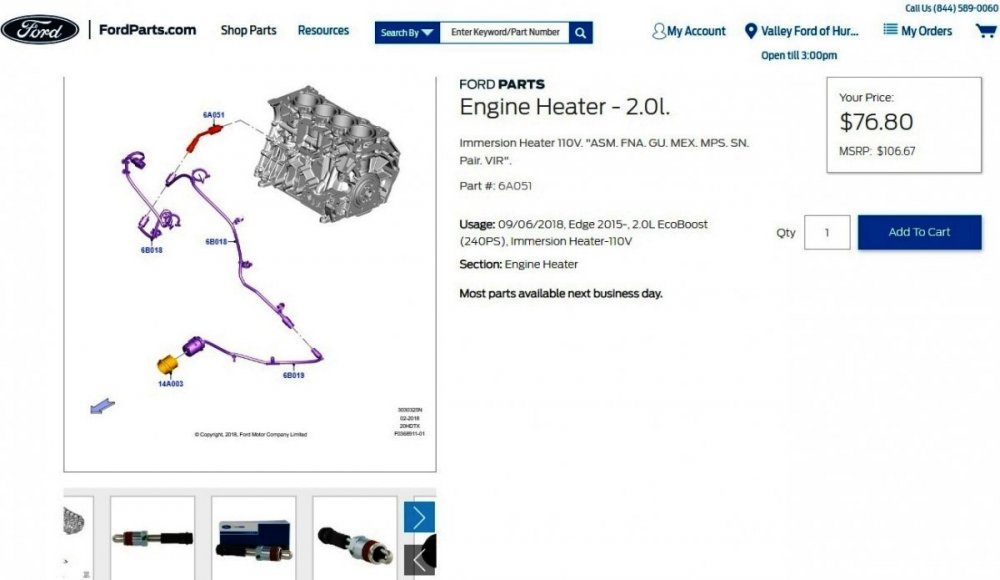
SSM 51385 2019-2023 Edge/Nautilus - 2.0L - Repeat Block Heater Failure - Updated Procedure In The Workshop Manual (WSM) Some 2019-2023 Edge/Nautilus vehicles equipped with a 2.0L engine may exhibit a repeat block heater failure. This may be caused by air in the engine cooling system. The WSM replacement procedure has been updated to include the Engine Cooling System Draining, Vacuum Filling and Bleeding procedure found in Section 303-03A Engine Cooling - 2.0L EcoBoost (184kW/250PS) – MI4, General Procedures as the final step. The block heater should not be tested unless all the air has been removed from the engine cooling system following this procedure. Document download links> Block Heater - Removal and Installation - 2.0L EcoBoost - 2023 Edge Workshop Manual.pdf Engine Cooling System Draining, Vacuum Filling and Bleeding - 2.0L EcoBoost - 2023 Edge Workshop Manual.pdf Link to 2.0L EcoBoost Engine Block Heater on Ford's online parts website...
-
SSM 51381 2021-2023 Various Vehicles - Tire Sidewall Wavy/Indentation Appearance Some 2021-2023 Ford and Lincoln vehicles may experience a tire sidewall wavy/indentation appearance in the radial direction on one or both sidewalls. Sidewall wavy/indentation appearance is a common cosmetic characteristic of radial tire construction and will not affect the performance of the tire. Non-Ford supplemental document download> Tire Information Service Bulletin - Vol 21 No 4 - US Tire Manufacturers Association.pdf
-
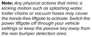
Released on February 14, 2023... SSM 51360 2021-2023 Edge Titanium/Nautilus - Unintended Hands-Free Liftgate Activation Some 2021-2023 Edge Titanium/Nautilus vehicles equipped with hands-free liftgate may exhibit unintended liftgate activation when coming in contact with the rear bumper cover when the passive key is located in the rear bumper detection area. This is a normal condition and repairs are not necessary. Switching the hands-free liftgate feature off through the vehicle settings or keeping the passive key away from the rear bumper detection area during these actions will prevent unintended activation from occurring. Refer to the Owner’s Manual Power Liftgate section for more details. It is worth noting that 2021-2023 Edge/Nautilus Owner's Manual sections covering Power Liftgate do not include any passage relating to "Switching the hands-free liftgate feature off through the vehicle settings" as mentioned in SSM 51360. The Owner Manuals do include... and... Good luck!

-
GSB 23-7003 - Various Vehicles - Paint And Bumper Concern Analysis
Haz replied to Haz's topic in Recalls, TSBs & Warranty
Document download link> 2017 Model Year Warranty Guide - Version 3 - August 2016.pdf From page 16 of 41 in the PDF... Extended warranty coverage periods are available for certain vehicle parts and conditions. Specifically, (3) Your vehicle’s body sheet metal panels are covered for an extended Corrosion Coverage Period, which lasts for five years, regardless of miles driven. The extended warranty coverage only applies if a body sheet metal panel becomes perforated due to corrosion during normal use due to a manufacturing defect in factory-supplied materials or factory workmanship. If aluminum body panels have corrosion or rust damage, and the damage is not the result of abnormal usage, vehicle accident, customer actions and/or extreme environmental conditions, the corrosion or rust damage repairs are covered for 5 years, unlimited miles. For damage caused by airborne material (environmental fallout) where there is no factory-related defect involved and therefore no warranty - our policy is to provide free repair of paint damage due to the airborne material for 12 months or 12,000 miles, whichever occurs first. Good luck! -
Released on January 23, 2023... SSM 51314 2021-2023 Mustang Mach-E/F-150/Edge/Nautilus, 2022-2023 Expedition/Navigator/Bronco, 2023 Escape/Transit/Corsair - DTC U3000:57 - Unable To Clear Some 2021-2023 Mustang Mach-E/F-150/Edge/Nautilus, 2022-2023 Expedition/Navigator/Bronco, 2023 Escape/Transit/Corsair vehicles may exhibit a diagnostic trouble code (DTC) U3000:57 stored in the accessory protocol interface module (APIM), telematics control unit (TCU), and/or gateway modules (GWM) that will not clear. The presence of this DTC means that an engineering analytic token is present on the vehicle. This analytical token does not affect module functionality or features used by the customer. No attempts should be made to repair this DTC.
-
GENERAL SERVICE BULLETIN Various Vehicles - Paint And Bumper Concern Analysis 23-7003 18 January 2023 This bulletin supersedes 22-7023. Summary This article supersedes GSB 22-7023 to update the Service Information. This article is designed to provide examples of paint conditions / damage to assist in determining if the condition is warrantable / non-warrantable. Refer to the latest version of the Warranty and Policy manual for the latest paint damage warranty coverage. Paint damage is only warrantable on the original factory paint. Use this document to assist in determining warrantable paint concerns. Service Information Ford Motor Company recommends that when resolving customer paint finish appearance concerns, every effort should be made to preserve the factory paint and corrosion protection. Repairing or improving paint finish appearance concerns with touch-ups and polishing techniques should be considered whenever possible as an alternative to removing and refinishing painted surfaces. Minor imperfections in sheet metal seams (inside door areas, inside liftgates, tailgate and under hood areas) can be considered normal in some situations. Efforts to repair or refinish these areas for minor cosmetic defects may compromise or remove the factory corrosion protection and may cause long-term durability concerns. Make sure the vehicle owner is aware of these conditions before attempting repairs. Environmental damage can be removed by following the Environmental Fallout Procedure detailed in Section 501 of the Workshop Manual. Once the environmental damage is removed, buffing and polishing may be required. According to the Owner’s Manual, owners are expected to wash and wax their vehicle regularly, including the bumper system, to remove harmful deposits from the vehicle’s surfaces to help protect the finish. Clean the chrome and stainless steel parts with polish to prevent rust or corrosion. IMPORTANT: Follow the guidelines within the vehicle’s Owner's Manual when cleaning chrome and/or stainless steel parts. Non-warrantable Conditions • Surface rust and deterioration of paint, trim, and appearance items that result from use and/or exposure. • Dents, dings, scratches, nicks, chips, punctures, bird and/or bee droppings, tree sap, road salt. • Normal paint deterioration due to exposure. • Underbody surface rust on frame or chassis components on vehicles reported as sold. Warranty Conditions • Bumper under-chrome defects; thin or peeling chrome. • Paint runs, over spray, sags, blistered / peeling paint. • Excessive dirt specs in paint. • Thin paint, orange peel. • Wavy sheet metal, file, grinder or weld marks. • Outward sheet metal dents. • Surface corrosion with no impact present is covered under the New Vehicle Warranty. The Corrosion Warranty also covers surface corrosion on aluminum body panels, however steel body panels would require sheet metal perforation caused by naturally occurring corrosion. - NOTE: See the Warranty and Policy Manual for more information and for specific coverages. • Iron oxide (rail dust) or acid rain. - NOTE: Although not a factory defect, damage caused by airborne material / environmental fallout damage (such as rail dust or acid rain) to exterior finish has limited coverage according to the Warranty and Policy Manual. Refer to the OWS User Guide for correct claiming sub code Dirt In The Finish (Warrantable) Dirt, sealer, and other debris trapped during the factory finish application. (Figures 1-2) Figure 1 Figure 2 Impact (Chips, Dents, Etc.) (Non-warrantable) Impact damage causing removed finish, substrate damage, and jagged edges. (Figures 3-4) Figure 3 Figure 4 Peeling (Warrantable) Peeling (without damage) to indicate an adhesion defect. (Figures 5-6) Figure 5 Figure 6 Peeling/Cracking Paint (With Damage) (Non-warrantable) Peeling or cracks occur from stress due to impact or flexing of the substrate. (Figures 7-8) Figure 7 Figure 8 Runs/Thin Paint (Warrantable) Causes include excessive or lack of material. (Figures 9-10) Figure 9 Figure 10 Stains (Non-warrantable) Stains may exhibit a drip pattern from abrasive liquids. Etching cannot be felt and will appear dull. (Figures 11-12) Figure 11 Figure 12 Orange Peel, Popping (Warrantable) Small texture differences best seen in a reflection of light. (Figures 13-14) Figure 13 Figure 14 Abrasion, Wear (Non-warrantable) Impact and abrasion. (Figures 15-16) Figure 15 Figure 16 Paint Color Variation (Warrantable) Normal variations are seen with different substrates but color differences should not be noted from all angles. (Figures 17-18) Figure 17 Figure 18 Etching From Abrasives Including Environmental (Non-warrantable) Bird and bee droppings, tree sap. Etching (discolored) cannot be felt. Cracking/removed finish. (Figures 19-20) Figure 19 Figure 20 Environmental Fallout (Limited Coverage) Although this is not a factory defect, damage caused by airborne material / environmental fallout (such as rail dust or acid rain) to exterior finish has limited coverage outlined in the Warranty and Policy Manual. Refer to the OWS User Guide for correct claiming sub code and the Workshop Manual for the environmental fallout removal procedure. (Figures 21-22) Figure 21 Figure 22 Corrosion (Warrantable) Surface corrosion with no impact present is covered under the New Vehicle Warranty. (Figures 23-24) The Corrosion Warranty also covers surface corrosion on aluminum body panels, however steel body panels would require sheet metal perforation caused by naturally occurring corrosion. See the Warranty & Policy Manual for more information. Figure 23 - Steel body panels - corrosion with no perforation (warrantable under New Vehicle Warranty only) Figure 24 - Aluminum body panels - corrosion (warrantable under New Vehicle and Corrosion Warranty with no perforation requirement) Corrosion (Non-warrantable) Surface corrosion which can be removed with cleaning. (Figure 25) Corrosion caused by damage. (Figure 26) Figure 25 Figure 26 Rust Perforation (Warrantable) Rust damage resulting in perforation (holes). Figure 27 - Steel body panels - corrosion with perforation (covered under the Corrosion Warranty) Mechanically Caused Perforation (Non-warrantable) Corrosion must be naturally occurring. (Figure 28) Figure 28 Previous Repair (Non-warrantable) Indicated by peeling paint atop the same/different color. Visible body filler. (Figures 29-30) Figure 29 Figure 30 Clear Coat Peeling (Non-warrantable) The factory paint process bonds color and clear coats together preventing clear coat peeling. (Figures 31-32) Figure 31 Figure 32 © 2023 Ford Motor Company All rights reserved. NOTE: This information is not intended to replace or supersede any warranty, parts and service policy, workshop manual (WSM) procedures or technical training or wiring diagram information.
-
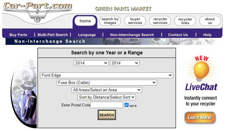
Welcome to the Forum! Document download links> Body Control Module (BCM) - Diagnosis and Testing - 2014 Edge Workshop Manual.pdf Body Control Module (BCM) - Removal and Installation - 2014 Edge Workshop Manual.pdf If your Edge is disabled and you need to get it back on the road, locating an A-graded used Body Control Module (BCM) from a local Salvage Yard at 25%-to-50% of the new part cost using the Car-Part.com search engine may be worthwhile... Good luck!
-FordParts.thumb.jpg.c31fd72e77a14a7f60ec91e00c1929b2.jpg)
-
Fluttering Noise from Undercarriage and Dashboad Rattle
Haz replied to CCMAYES72's topic in Brakes, Chassis & Suspension
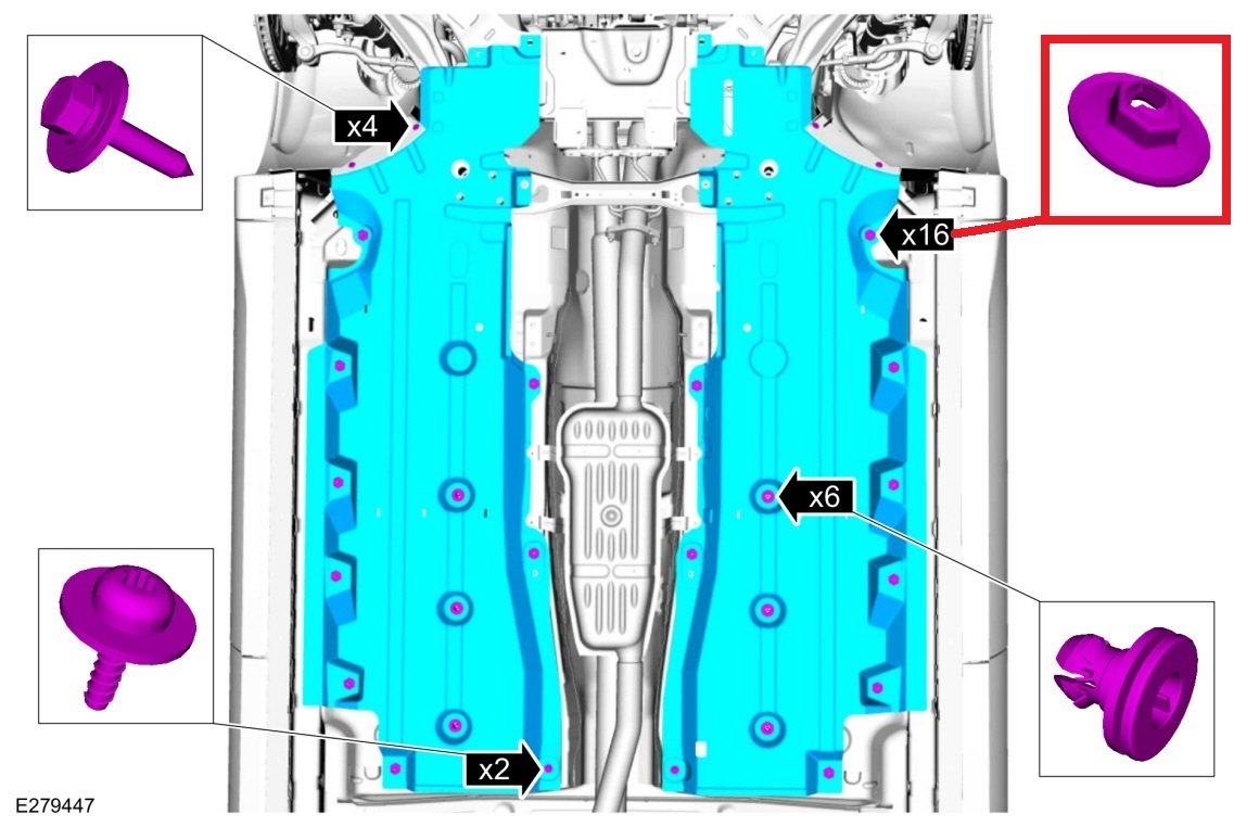
From the 2019 Edge Workshop Manual... The stamped sheet metal hex nut is also described online as a speed nut. I was unable to pick off the fastener part number from FordParts.com, though a dealership parts staffer will likely find it. On the other hand, providing 1004ron's photo to a local or national-brand auto parts store or hardware store may provide the part quicker and cheaper. Good luck!
- 83 replies
-
- 1
-

-
- dash noise
- dash rattle
- (and 4 more)
-
The 2022 Edge Workshop Manual offers this Auto-Start-Stop operational description and lists the conditions under which Auto-Start-Stop will not function... Auto-Start-Stop System The Auto-start-stop system helps reduce fuel consumption by automatically shutting off the vehicle’s engine while the vehicle is at a complete stop and restarting the engine when the brake pedal is released. The system can be disabled through the auto-start-stop control switch on the instrument panel centerstack. The Auto-start-stop system is automatically enabled whenever the ignition is turned on. The engine automatically restarts when: the brake pedal is released. the Auto-start-stop system is disabled through the auto-start-stop control switch on the instrument panel centerstack. the battery has a low state of charge. it is necessary to maintain interior comfort. the blower fan speed is increased or the climate control temperature is changed. an electrical accessory is turned on or plugged in. there is low brake vacuum. The Auto-start-stop system may not turn the engine off under these conditions: the HVAC system is in A/C, heat or defrost modes. the rear defroster is on. the battery has a low state of charge. the battery temperature is below 5°C (41°F) or above 60°C (140°F). the engine temperature is below 46°C (115°F). the engine temperature is below 60°C (140°F) and the HVAC system is in heat mode. the gear selector is not in Drive or Sport Mode. the steering wheel is turned rapidly or is at a sharp angle. vehicle speed of greater than 4 km/h (2.5 mph) for more than 2 seconds has not occurred. the vehicle is on a steep road grade. elevation is approximately above 3,048 meters (10,000 feet). Good luck!
-
Welcome to the Forum, Skipper96. Parasitic battery drain diagnostic reference... Document download link> Parasitic Battery Drain Job Aid.pdf Good luck!
-
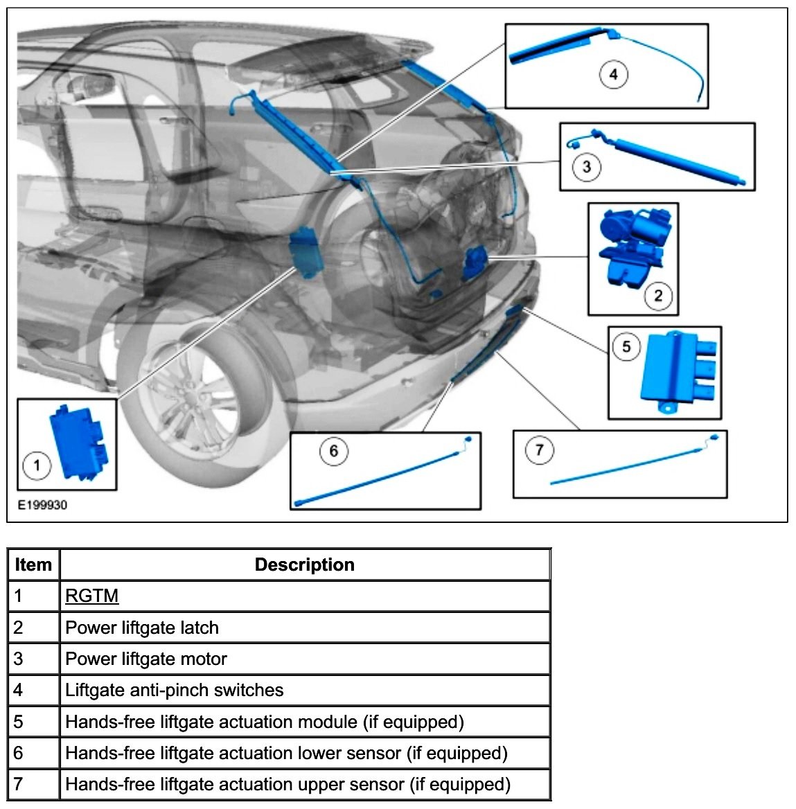
Because your Edge is exhibiting several Power Liftgate symptoms -- change in open/close velocity; a sporadic failure to pulldown and/or latch; cargo area pushbutton opens but does not close while exterior pushbutton performs normally -- the best-first step may be to perform the Power Liftgate Initialization procedure, which involves de-powering the Rear Gate Trunk Module (RGTM)... Document download link> Power Liftgate Initialization - 2016 Edge Workshop Manual.pdf You will notice this RGTM de-powering can be done either by pulling the RGTM fuses or by disconnecting the Edge's battery. If you choose pulling fuses, there are two -- F76 in the Battery Junction Box (BJB) and F10 in the Body Control Module (BCM)... Battery Junction Box (BJB) Images Release the tabs. Lift and position the top part of the junction box aside. Body Control Module (BCM) Images de-powering Be aware that the alternative RGTM de-powering method -- Battery Disconnect procedure -- offers these cautions... NOTICE: Removing the negative battery ground cable at the LH strut tower will not disable the vehicle's electrical system. Failure to disconnect the battery cable from the battery post may cause component damage. NOTE: When the battery is disconnected and connected, some abnormal drive symptoms may occur while the vehicle relearns its adaptive strategy. The vehicle may need to be driven to allow the PCM to relearn the adaptive strategy values. Document download link> Battery Disconnect and Connect - General Procedures - 2016 Edge Workshop Manual.pdf The following Workshop Manual section provides a wonderful explanation of Power Liftgate operation in conjunction with the RGTM and other components... Document download link> Power Liftgate System - Description and Operation - 2016 Edge Workshop Manual.pdf Please report back on the outcome of the Power Liftgate Initialization procedure. Good luck!
PowerSourceWiringDiagramHighlighted-2016EdgeWorkshopManual.thumb.jpg.56d64405e4caec1455edc94e14b04142.jpg)
-TopViewDiagram-2016EdgeWorkshopManual.thumb.jpg.07e573f55054557712a853c5fd2d7517.jpg)
Image1-FordPartsWebsite.thumb.jpg.4abbf3f900a0a905c5eba8f6535e3f7f.jpg)
Image2-FordPartsWebsite.thumb.jpg.c8187c0edb9ce8ab28c9fb2c05364597.jpg)
Image3-FordPartsWebsite.thumb.jpg.e5487a31eab0c4b340819be50322f858.jpg)
Image4-FordPartsWebsite.thumb.jpg.661f8ea65d450e7432420b3fdc54faea.jpg)
-BottomViewDiagramHighlighted-2016EdgeWorkshopManual.thumb.jpg.c51f8eaea7513beb56579c4be97366e3.jpg)
In-PlaceIllustration-2016EdgeWorkshopManual.jpg.f73c412529a9a93d9b0cd9be12fbaf8a.jpg)
DiagramHighlighted-2016EdgeWorkshopManual.thumb.jpg.b6cbec5b2062cebc98af421710ece700.jpg)
ImageHighlighted-FordPartsWebsite.thumb.jpg.36e98a06820d74ed2ced265c32d8bc46.jpg)
In-PlaceIllustration-2016EdgeWorkshopManual.jpg.175292f3d47024f9b7e261e7abf55351.jpg)

-
The following is a PDF document download link to the relevant section from the Edge Workshop Manual... Windshield Wiper Pivot Arm - Removal and Installation - 2022-2023 Edge Workshop Manual.pdf It includes this guidance, which the windshield installer may not have done... Installation NOTICE: The ignition switch must be set to the ON position. Power is required to hold the wiper motor in the PARK position. No power or low battery voltage will allow the motor to move from the PARK position during the torquing operation resulting in incorrect wiper arm position. Good luck!
-
Welcome to the Forum! Below are relevant sections from the 2019 Edge Workshop Manual... Document download links> Rear Spoiler - Removal and Installation - 2019 Edge Workshop Manual.pdf High Mounted Stoplamp - Removal and Installation - 2019 Edge Workshop Manual.pdf Good luck!
-
Welcome to the Forum! This Special Service Message was released on December 23, 2021... SSM 50375 2016-2021 Various Vehicles - Loss of Navigation Voice Prompts After A SYNC Map Update Some 2016-2021 Ford and Lincoln vehicles equipped with SYNC 3 may exhibit a condition where the navigation voice prompts are inoperative after a SYNC map update. This may be due to an incomplete installation of the SYNC map software. If possible, using the original USB that installed the update, reperform the update and verify the navigation voice prompts have returned. Multiple reboots are expected when this update is being performed. Verify the Installation Is Complete message displays in the touch screen. If the original USB is not available, go to website https://syncnavigation.com/ford/home or https://syncnavigation.com/lincoln/home to download the files once more for the affected vehicle. For further map update support, reference the FAQ section on these websites. Additionally, the following SYNC-related Technical Service Bulletin was released on June 2, 2021... Document download link> TSB 21-2175 - 2016-2019 Various Vehicles - SYNC 3 – Various SYNC Performance Related Concerns.pdf Good luck!
-
Welcome to the Forum! Based upon your comment that the battery won't hold a charge, you may want to have the battery tested to determine if it has a failing or failed cell(s). Low battery voltage alone will induce a myriad of Diagnostic Trouble Codes (DTCs) and electronic module symptoms, and replacing a failing/failed battery may (surprisingly) clear up many problems. Please report back on the outcome, and I'll gladly supply diagnostic procedures to address any enduring DTCs that your Edge exhibits. Good luck!
-
From the 2014 Edge-MKX Workshop Manual... Document download links> Crankshaft Rear Seal - In-Vehicle Repair - 2014 Edge-MKX Workshop Manual.pdf Crankshaft Rear Seal With Retainer Plate - In-Vehicle Repair - 2014 Edge-MKX Workshop Manual.pdf Good luck!
-
Relevant sections from the 2018 Edge Workshop Manual... Document download links> Liftgate Latch Manual Release - 2018 Edge Workshop Manual.pdf Liftgate Latch - Removal and Installation - 2018 Edge Workshop Manual.pdf Liftgate Trim Panel - Removal and Installation - 2018 Edge Workshop Manual.pdf Power Liftgate Initialization - 2018 Edge Workshop Manual.pdf Power Rear Liftgate - Diagnosis and Testing - 2018 Edge Workshop Manual.pdf Power Liftgate Wiring Diagram 1 - 2018 Edge Workshop Manual.pdf Power Liftgate Wiring Diagram 2 - 2018 Edge Workshop Manual.pdf Power Liftgate Wiring Diagram 3 - 2018 Edge Workshop Manual.pdf Power Liftgate Wiring Diagram 4 - 2018 Edge Workshop Manual.pdf Power Liftgate Wiring Diagram 5 - 2018 Edge Workshop Manual.pdf Power Rear Liftgate - Component Location - 2018 Edge Workshop Manual.pdf Power Rear Liftgate - System Operation - 2018 Edge Workshop Manual.pdf Owner comments in this past discussion should be helpful to you. Good luck!
-
Welcome to the Forum! From the 2011 Edge Workshop Manual... Instrument Cluster and Panel Illumination - Principles of Operation Dimmable Backlighting The instrument panel dimmer switch is integral to the Front Lighting Control Module (FLM) . When the parking lamps are on, the FLM sends an illumination command message to the Body Control Module (BCM) over the High Speed Controller Area Network (HS-CAN) . The BCM sends voltage to the hardwired dimmable components and switches based on the network message received from the FLM . The BCM also sends a message over the Controller Area Network (CAN) to the Instrument Panel Cluster (IPC) , the FLM and the HVAC module, to indicate the backlighting intensity level. The IPC gateways the message from the HS-CAN to the Infotainment Controller Area Network (I-CAN) to the Front Controls Interface Module (FCIM) , the Front Control/Display Interface Module (FCDIM) (if equipped), and the Accessory Protocol Interface Module (APIM) (if equipped). If equipped, the Front Display Interface Module (FDIM) is attached to the APIM . The APIM gateways the illumination intensity level message to the FDIM . A bar graph window is displayed in the message center of the IPC indicating the backlighting intensity level. If the receiving module receives invalid backlighting data from the BCM for 5 seconds or less, the receiving module defaults the backlighting to the last setting. If the receiving module does not receive the backlighting status message from the BCM or if the data received is deemed invalid for more than 5 seconds, the receiving module sets a DTC in continuous memory and defaults the backlighting to full nighttime intensity. Non-Dimmable Backlighting (Edge only) When the accessory delay relay is energized, switched voltage is supplied to the window control and door lock control switches. Field-Effect Transistor (FET) Protection A Field-Effect Transistor (FET) is a type of transistor that, when used with module software, can be used to monitor and control current flow on module outputs. The FET protection strategy prevents module damage in the event of excessive current flow. The BCM utilizes an FET protective circuit strategy for many of its outputs (for example, a headlamp output circuit). Output loads (current level) are monitored for excessive current (typically short circuits) and are shut down (turns off the voltage or ground provided by the module) when a fault event is detected. A short circuit DTC is stored at the fault event and a cumulative counter is started. When the demand for the output is no longer present, the module resets the FET protection to allow the circuit to function. The next time the driver requests a circuit to activate that has been shut down by a previous short (FET protection) and the circuit is still shorted, the FET protection shuts off the circuit again and the cumulative counter advances. When the excessive circuit load occurs often enough, the module shuts down the output until a repair procedure is carried out. Each FET protected circuit has 3 predefined levels of short circuit tolerance based on the harmful effect of each circuit fault on the FET and the ability of the FET to withstand it. A module lifetime level of fault events is established based upon the durability of the FET . If the total tolerance level is determined to be 600 fault events, the 3 predefined levels would be 200, 400 and 600 fault events. When each tolerance level is reached, the short circuit DTC that was stored on the first failure cannot be cleared by the clear the continuous DTCs command. The module does not allow this code to be cleared or the circuit restored to normal operation until a successful self-test proves the fault has been repaired. After the self-test has successfully completed (no on-demand DTCs present), DTC U1000:00 and the associated DTC (the DTC related to the shorted circuit) automatically clears and the circuit function returns. When each level is reached, the DTC associated with the short circuit sets along with DTC U1000:00. These DTCs are cleared using the module on-demand self-test, then the Clear DTC operation on the scan tool (if the on-demand test shows the fault corrected). The module never resets the fault event counter to zero and continues to advance the fault event counter as short circuit fault events occur. If the number of short circuit fault events reach the third level, then DTCs U1000:00 and U3000:49 set along with the associated short circuit DTC. DTC U3000:49 cannot be cleared and the module must be replaced after the repair. The BCM FET protected output circuit for the instrument cluster and panel illumination system is the dimmable switch output circuit. Document download link> Instrument Cluster and Panel Illumination - Diagnostics and Testing - 2011 Edge Workshop Manual.pdf And, just in case it is the Information and Entertainment Control Panel you're referring to... Document download link> Bezel Diagnostics - Information and Entertainment Systems General Procedures - 2011 Edge Workshop Manual.pdf And, just in case it is the SYNC System you're referring to... Document download link> Accessory Protocol Interface Module (APIM) Reset - Information and Entertainment Systems General Procedures - 2011 Edge Workshop Manual.pdf Good luck!
-
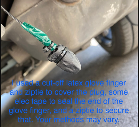
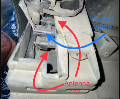
From the 2020 Edge Workshop Manual... Hands-Free Liftgate Actuation Module The hands-free liftgate actuation module is located behind the rear bumper cover on the right side of the vehicle. The hands-free liftgate actuation module receives a 12-volt signal from the BCM while monitoring 2 capacitive sensors. When the correct motion is detected from the upper and lower sensors, the hands-free liftgate actuation module momentarily grounds the voltage signal from the BCM . Hands-Free Liftgate Actuation Sensors The hands-free liftgate actuation sensors are capacitive sensors and generate capacitive fields near the rear bumper. The capacitive fields are disrupted when an object (such as a leg) enters the area. The hands-free liftgate actuation module uses this information to interpret movement near the rear bumper. In the above-linked Explorer ST Forum discussion, the Explorer owner uses the term 'Antenna Loop' to describe his vehicle's two separate Hands-Free Liftgate Actuation Sensors... Photo courtesy of KNTRDR ...which are mounted forward of the trailer hitch assembly in an upper-and-lower arrangement that is functionally identical to the two Sensors mounted on the inside of the Edge's rear bumper cover... Explorer Lower Hands-Free Liftgate Actuation Sensor Explorer Upper Hands-Free Liftgate Actuation Sensor The Explorer owner's direction is to disconnect the Upper Sensor and to leave the Lower Sensor plugged into the Hands-Free Liftgate Actuation Module, and there are no subsequent comments in that discussion saying the Hands-Free function continued to work after disconnecting the one Sensor. Looking to the Edge Workshop Manual description, the Module presumably compares electrical values generated from each Sensor and interprets simultaneous changes in the two Sensor inputs as the owner's leg sweep, which when the Intelligent Access key fob is within 3-feet of the Liftgate, triggers a power-open result (as long as the Power Liftgate is not deactivated via the Instrument Panel settings menu). So, disconnecting one Sensor may sufficient to prevent the Module from recognizing an underbody leg sweep, by eliminating the second Sensor's electrical input from comparison by the Module to the other connected Sensor's input. Unfortunately, the Hands-Free feature wasn't offered on our 2015 MKX, so I cannot personally test the difference between disconnecting one Sensor versus disconnecting both Sensors from the Hands-Free Liftgate Actuation Module. The Explorer owner's recommendation to use vinyl/nitrile gloves' cutoff finger sections zip-tied to an unused connector or module receptacle for protection from water intrusion and road dirt is a great idea that I will surely use in the future... Photo courtesy of KNTRDR Good luck!
-
Also -- Welcome to the Forum! Good luck!


-FordParts.jpg.596b5983869211efa47351f0a2a4243f.jpg)
PowerSourceWiringDiagramHighlighted-2016EdgeWorkshopManual.jpg.b85211dcb9f9d9f3e932280adf189b8c.jpg)
-TopViewDiagram-2016EdgeWorkshopManual.jpg.8f3d841e22e84d3b5fdc0bedfa3de13d.jpg)
Image1-FordPartsWebsite.jpg.45e97dbf2b401ce801e82a3ef4a9a602.jpg)
Image2-FordPartsWebsite.jpg.3c3239aa7be51690a6fc5efddae01a35.jpg)
Image3-FordPartsWebsite.jpg.eb7135bf91854216bfb4f343e3a06df3.jpg)
Image4-FordPartsWebsite.jpg.b7d5e0126754f32936fcc2eb641f0091.jpg)
-BottomViewDiagramHighlighted-2016EdgeWorkshopManual.jpg.fbc484435c876300676161f15faaa762.jpg)
DiagramHighlighted-2016EdgeWorkshopManual.jpg.559c095ad96d7ff1e4aae9997a305264.jpg)
ImageHighlighted-FordPartsWebsite.jpg.f6744f72ed6bc11f8b2f110b6093b6dc.jpg)