Haz
-
Posts
1,476 -
Joined
-
Last visited
-
Days Won
395
Content Type
Profiles
Forums
Gallery
Everything posted by Haz
-
Just in case you wish to remove a trim panel to confirm your discovery... Document download links> Loadspace Trim Panel - Removal and Installation - 2016 Edge Workshop Manual.pdf Liftgate Trim Panel - Removal and Installation - 2016 Edge Workshop Manual.pdf Good luck!
-
Document download links> Fog Lamps Ground Circuit - G111 Terminating Location - 2019 Edge.pdf Fog Lamps Ground Circuit - Splice S189 Location - 2019 Edge.pdf Good luck!
-
Document download links> FOG LAMP, LEFT FRONT - Connector C152 Location - 2019 Edge.pdf FOG LAMP, RIGHT FRONT - Connector C162 Location - 2019 Edge.pdf
-
The body shop should be assessing fog lamp circuits wiring, harness connectors, and grounds termination. Right hand fog lamp wiring is contained in harness that routes inside the bumper cover to connector & ground on the left hand front corner of engine compartment. If animal impact damaged bumper cover, then perhaps harness was damaged, If repair required removal of the bumper cover, then perhaps connector pin was damaged or pushed out when connectors and the front end was reassembled. The body shop should be capable of chasing down the wiring/connector/ground issue caused by the original impact or by a reassembly mishap. The following Workshop Manual & Wiring resources should improve your awareness and equip the body shop techs to correct the problem... Document download links> Fog Lamps - Diagnosis and Testing - 2019 Edge Workshop Manual.pdf Fog Lamps Wiring Diagram -2019 Edge.pdf Front End Ground Circuits, Including Fog Lamps Ground - Wiring Diagram - 2019 Edge.pdf FOG LAMP, LEFT FRONT - Connector C152 Details - 2019 Edge.pdf FOG LAMP, RIGHT FRONT - Connector C162 Details - 2019 Edge.pdf Fog Lamps Power Circuit - Pins 15 (LH) & 16 (RH) of Inline Connector C140 - 2019 Edge.pdf BODY CONTROL MODULE (BCM) - Connector C2280B Details - 2019 Edge.pdf Front Bumper Cover - Disassembly and Assembly - 2019 Edge Workshop Manual.pdf Front Bumper Cover - Removal and Installation - 2019 Edge Workshop Manual.pdf Additional resources will be provided in immediately following posts...
-
Need help with inop heated seats and dcsm location
Haz replied to Rededge98290's topic in Interior, A.C., Heat, Interior Trim
Per Rededge98290's request... "It looks like the simplest cause to both seats not heating would be the failure of ground G302. Would you be able to share the location of that? If that's not the issue, then I'll dig into the step by step pinpoints" Document download links> Heated Seats - Ground G302 Location - Right Hand B-Pillar - 2013 Edge.pdf B-Pillar Trim Panel - Removal and Installation - 2013 Edge Workshop Manual.pdf Scuff Plate Trim Panel, Front - Removal and Installation - 2013 Edge Workshop Manual.pdf Scuff Plate Trim Panel, Rear - Removal and Installation - 2013 Edge Workshop Manual.pdf Good luck! -
Door Buttons Not Illuminated - Is This Normal?
Haz replied to McGruber's topic in Interior, A.C., Heat, Interior Trim
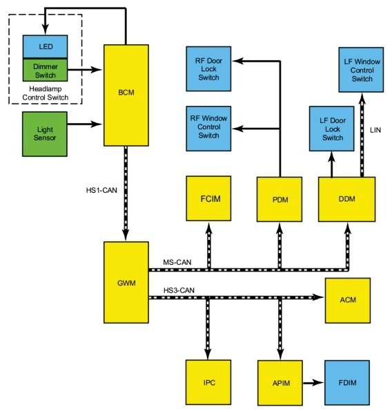
Welcome to the Forum, McGruber ! I'm curious if your headlamps were set to Autolamp, and if ignition was "on" with or without the engine running? The 2020 Edge Workshop Manual states door-panel switch backlighting is activated when parking lamps are "on", though parking lamps and dimmable backlighting are also temporarily "on" during Illuminated Entry and Exit, as described below... Placing your device cursor over underlined acronyms may yield full-word descriptions. Instrument Panel and Interior Switches Illumination System Operation System Diagram - Networked Illumination Network Message Chart Module Network Input Messages - ACM , APIM , DDM , FCIM , GWM , IPC and PDM . Broadcast Message Originating Module Message Purpose Illumination Dimming Level BCM Used to command the illumination dimming level for networked modules and outputs that are hardwired to networked modules. Networked Illumination Operation The dimmable switches and components are illuminated when the parking lamps are on. The system-wide illumination dimming level is determined by the BCM . Based on the ambient light level input from the light sensor and the requested illumination dimming level input from the dimmer switch, the BCM calculates the correct dimming level. The BCM sends the illumination dimming level message to the GWM on the HS-CAN1 . The GWM distributes the message to the following components: MS-CAN FCIM DDM PDM HS-CAN3 IPC APIM ACM The receiving modules use the illumination dimming level message to determine the backlighting intensity of internal and external non-networked illumination sources. If a module does not receive the illumination dimming level message or the data received is deemed invalid, the module sets a DTC in continuous memory and defaults to full nighttime intensity. If the IPC does not receive the dimming level or ambient light level network messages from the BCM for up to 5 seconds, the IPC illumination remains at the last level based on the last message received. If the IPC receives invalid or no signals for more than 5 seconds, the IPC defaults to full night illumination level. On vehicles equipped with autolamps, if the exterior lamps are activated during the daytime, the message center illumination remains at full intensity and does not dim from the illumination dimmer switch. If the vehicle travels under a bridge or through a tunnel, the low level of ambient light causes the illumination level of the message center to change to the level set by the illumination panel dimmer switch. The message center illumination changes back to full intensity when the intense ambient light is restored. The hazard switch is integral to the FCIM and cannot be serviced separately. System Diagram - Non-Networked Illumination Non-Networked Illumination Operation Based on the ambient light level input from the light sensor and the requested illumination dimming level input from the dimmer switch, the BCM calculates the correct dimming level for the non-networked illumination sources. The BCM provides a pulse-width modulated voltage to all non-networked illumination sources on two circuits. Field-Effect Transistor (FET) Protection Field-Effect Transistor (FET) protection is used to protect the BCM output drivers from damage in the event an excessive current draw is detected on a BCM output. Each illumination circuit connected to the BCM is separately protected. Refer to the System Diagram in this section to view the different groups of BCM non-networked illumination outputs. Component Description Dimmer Switch The illumination dimmer switch is a momentary contact switch that is integral to the headlamp switch. The headlamp switch is non-networked to the BCM . When the illumination dimmer switch is pressed up or down, the switch completes a ground circuit to the BCM corresponding to the desired action (increase or decrease illumination brightness). Field Effect Transistor (FET) Protection The BCM utilizes an Field Effect Transistor (FET) protective circuit strategy for many of its outputs, for example, lamp output circuits. Output loads (current level) are monitored for excessive current (typically short circuits) and are shut down (turns off the voltage or ground provided by the module) when a fault event is detected. A Field Effect Transistor (FET) is a type of transistor that the control module software uses to control and monitor current flow on module outputs. The Field Effect Transistor (FET) protection strategy prevents module damage in the event of excessive current flow. Output loads (current level) are monitored for excessive current draw (typically short circuits). When a fault event is detected the Field Effect Transistor (FET) turns off and a short circuit DTC sets. The module resets the Field Effect Transistor (FET) protection and allows the circuit to function when the fault is corrected or the ignition state is cycled off and then back on. When the excessive circuit load occurs often enough, the module shuts down the output until a repair procedure is carried out. Each Field Effect Transistor (FET) protected circuit has three predefined levels of short circuit tolerance based on a module lifetime level of fault events based upon the durability of the Field Effect Transistor (FET). If the total tolerance level is determined to be 600 fault events, the three predefined levels would be 200, 400 and 600 fault events. When each level is reached, the DTC associated with the short circuit sets along with DTC U1000:00. These Diagnostic Trouble Codes (DTCs) can be cleared using the module on-demand self-test, then the Clear DTC operation on the scan tool (if the on-demand test shows the fault corrected). The module never resets the fault event counter to zero and continues to advance the fault event counter as short circuit fault events occur. If the number of short circuit fault events reach the third level, then Diagnostic Trouble Codes (DTCs) U1000:00 and U3000:49 set along with the associated short circuit DTC . DTC U3000:49 cannot be cleared and the module must be replaced after the repair. Interior Lighting - System Operation Illuminated Entry and Exit The illuminated entry and exit features provide temporary illumination of the parking lamps, the dimmable backlighting, the ambient backlighting and the courtesy lamps. Refer to the table for additional information. NOTE: An arbitrator (software programming) within the BCM determines which actions take precedence over others (for example, an open door keeps the courtesy lamps on even when a command to lock the doors is received). Action Parking Lamps Courtesy Lamps Dimmable Backlighting Ambient Lighting RKE transmitter or mechanical unlocking of the doors On for 25 seconds On for 25 seconds On for 25 seconds Off RKE transmitter or mechanical locking of the doors Off Off Off Off 3 seconds after courtesy lamps turned off Open a closed door after previously unlocking (no ignition state change since unlock) Off (on for remaining time if unlocked from transmitter or mechanical unlocking of the doors) On Off On Close all doors Off On for 25 seconds On for 25 seconds On for 25 seconds Ignition changed to ON Off On for 25 seconds Off On Ignition changed out of ON Off On for 25 seconds On for 25 seconds On for 25 seconds Open a door after the ignition is changed to OFF Off On Off On (color is red on the open door) Ignition is OFF and doors are unlocked from the door lock switch Off On for 25 seconds Off Off Ignition is OFF and doors are locked from the door lock switch Off Off Off Off Good luck!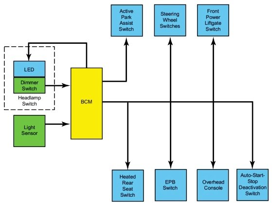
-
Need help with inop heated seats and dcsm location
Haz replied to Rededge98290's topic in Interior, A.C., Heat, Interior Trim
Additional diagnostic document download links> HEATED SEAT ELEMENT, RIGHT FRONT - Connector 3284 Location - 2013 Edge.pdf HVAC MODULE, DATC - Connector 228A Location - 2013 Edge.pdf HVAC MODULE, DATC - Connector 228B Location - 2013 Edge.pdf Battery Junction Box (BJB) Diagram - 2013 Edge.pdf Battery Junction Box (BJB) Fuse-Circuit Legend - 2013 Edge.pdf Good luck! -
Need help with inop heated seats and dcsm location
Haz replied to Rededge98290's topic in Interior, A.C., Heat, Interior Trim
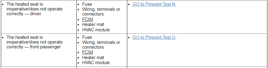
Welcome to the Forum, Rededge ! You were unsuccessful finding a DCSM on your front seat heat-only 2013 Edge Limited because the Dual Climate Seat Module (DCSM) is only installed on vehicles equipped with heated-and-cooled (dual climate) seats. So, there's no DCSM hidden on your vehicle, though on vehicles with dual climate seats, the DCSM is mounted under the passenger seat. From the 2013 Edge Workshop Manual... Front Seats - Heated Seats WARNING: Never install heated seat parts not intended for use on this vehicle. Parts released for other model years or vehicle lines are not compatible even if they appear visually and physically similar. Installing incorrect parts will result in heated seat system performance outside design specification. Failure to follow this instruction may result in serious personal injury. This system allows independent seat electrical heating of each front seat on demand. The components of the system are: seat heater mats located on the seat cushion and backrest. the HVAC module heated seat buttons, located on the touchscreen interface (if equipped) or the Front Controls Interface Module (FCIM) . temperature sensors, located in the seat cushion heater mats. A new heater mat comes assembled on a new foam pad. The driver and passenger heated seat control buttons and indicators are located on the Front Controls Interface Module (FCIM) or touchscreen interface (if equipped). The heated seat system functions independently of the vehicle's climate control system. Each time the heated seat button is pressed, the FCIM sends the request message to the HVAC module which decreases one setting (the sequence is hi, low, OFF, hi, etc.). For vehicles without a touchscreen interface, when a heated seat is set to hi, both LED indicators above that heated seat's control button illuminate. When a heated seat is set to low, only one LED indicator above that switch illuminates. When off, no indicators illuminate. When activated, the HVAC module supplies voltage to the selected seat's heater circuit. Each seat's cushion heater mat and backrest heater mat is connected in a series circuit to the HVAC module and powered by the output circuit for that seat. The HVAC module monitors inputs from a temperature sensor located in each seat's cushion heater mat, and maintains seat temperature by cycling the heater circuits on/off. The heated seat remains ON until the heated seat switch button is pressed to cycle the HVAC module OFF or the ignition is set to OFF. If a fault is detected by the HVAC module, the module stops supplying voltage to that individual left or right seat that the fault was detected on until the ignition is turned OFF and then ON. Diagnostic document download links> Heated Seat Is Inoperative - Driver & Passenger Diagnostic Pinpoint Tests ''N'' & ''O'' - 2013 Edge Workshop Manual.pdf Heated Seats - Wiring Diagram Cell 119 - 2013 Edge.pdf Supplemental Restraint System (SRS) Depowering and Repowering - General Procedures - 2013 Edge Workshop Manual.pdf HEATED SEAT ELEMENT, RIGHT FRONT - Connector 3284 Details - 2013 Edge.pdf HEATED SEAT ELEMENT, LEFT FRONT - Connector 3283 Details - 2013 Edge.pdf HEATED SEAT ELEMENT, LEFT FRONT - Connector 3283 Location - 2013 Edge.pdf HVAC MODULE, DATC - Connector 228A Details - 2013 Edge.pdf HVAC MODULE, DATC - Connector 228B Details - 2013 Edge.pdf Driver Seat Side Air Bag - Inline Connector C328 Details - 2013 Edge.pdf Driver Seat Side Air Bag - Inline Connector C328 Location - 2013 Edge.pdf HVAC MODULE, DATC - Connector 228A Details - 2013 Edge.pdf HVAC MODULE, DATC - Connector 228B Details - 2013 Edge.pdf Driver Seat Side Air Bag - Inline Connector C328 Details - 2013 Edge.pdf Driver Seat Side Air Bag - Inline Connector C328 Location - 2013 Edge.pdf Passenger Seat Side Air Bag - Inline Connector C327 Details - 2013 Edge.pdf Passenger Seat Side Air Bag - Inline Connector C327 Location - 2013 Edge.pdf Body Control Module (BCM) - Removal and Installation - 2013 Edge Workshop Manual.pdf Body Control Module (BCM) - R & I Enhanced Image #1 - 2013 Edge Workshop Manual.pdf Body Control Module (BCM) - R & I Enhanced Image #2 - 2013 Edge Workshop Manual.pdf Heating Ventilation Air Conditioning (HVAC) Module - Removal and Installation - 2013 Edge Workshop Manual.pdf Heating Ventilation Air Conditioning (HVAC) Module - R & I Enhanced Image #1 - 2013 Edge Workshop Manual.pdf Heating Ventilation Air Conditioning (HVAC) Module - R & I Enhanced Image #2 - 2013 Edge Workshop Manual.pdf Heating Ventilation Air Conditioning (HVAC) Module - R & I Enhanced Image #3 - 2013 Edge Workshop Manual.pdf Additional diagnostic documents will be provided in my next post...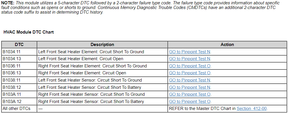

-
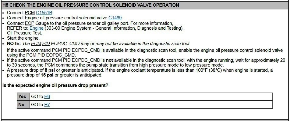
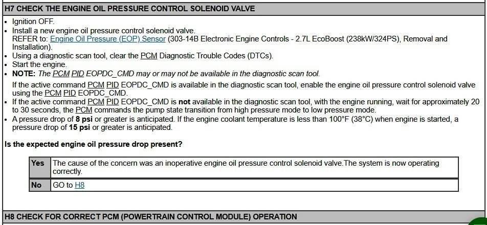
Perhaps your Workshop Manual extract is from prior to October 15, 2019, when that 2015 Specifications page was revised... Oil Pressure NOTE: The following oil pressure readings are acquired using a scan tool and monitoring the EOP_PRESS PID. Item Specification Reading 1: Minimum average oil pressure @ 2,000 rpm after 15 secs with engine at normal operating temperature and transmission in Park 21 psi (144.8 kPa) Reading 2: Minimum average oil pressure @ 2,000 rpm after 15 secs with engine at normal operating temperature and transmission in Park (Oil Pressure Control Solenoid connector disconnected) Reading 1 value plus 8 psi (55.1 kPa) Your supposition on the Oil Pressure Control Solenoid affect is confirmed by Steps 5 & 7 of Electronic Engine Controls diagnostic Pinpoint Test H... Document download link> Oil Pressure Control Solenoid Removal and Installation - 2015 Edge Workshop Manual, Revised 01-09-2015.pdf (consistent with 2016 Edge Workshop Manual) Good luck! Edit: I neglected to include... DTC Fault Trigger Condition-PCM DTC Description Fault Trigger Conditions P06DA Engine Oil Pressure Control Circuit/Open Sets when the PCM detects an open on the engine oil pressure control solenoid valve circuit. P06DB Engine Oil Pressure Control Circuit Low Sets when the PCM detects a short to ground on the engine oil pressure control solenoid valve circuit. P06DC Engine Oil Pressure Control Circuit High Sets when the PCM detects a short to voltage on the engine oil pressure control solenoid valve circuit. P06DD Engine Oil Pressure Control Circuit Performance/Stuck Off Sets when the PCM detects the engine oil pressure control solenoid valve is stuck. Possible Sources Engine oil pressure control solenoid valve PCM Wiring, terminals or connectors

-
Sunroof rear brackets loose (Gen2)
Haz replied to omar302's topic in Glass, Lenses, Lighting, Mirrors, Sunroof (BAMR), Wipers
No related TSBs found, with this being the only communicated 2016 Edge Sunroof noise/vibration/harshness issue... SSM 49679 2015-2020 Edge, 2016-2018 MKX, 2019-2020 Nautilus - NVH Concerns After Replacement Of Roof Opening Panel Frame Some 2015-2020 Edge, 2016-2018 MKX, and 2019-2020 Nautilus vehicles may require replacement of the roof opening panel track or frame for various conditions. When replacing the roof opening panel, the replacement component may have less magnet plates. In order to prevent any noise vibration or harshness (NVH) concerns, the magnets on the headliner around the roof opening panel that line up with the removed magnet plates should be discarded. Good luck! -
Edge 2.7 EcoBoost specification from the 2016 Workshop Manual... Oil Pressure NOTE: The following oil pressure readings are acquired using a scan tool and monitoring the EOP_PRESS PID. Item Specification Reading 1: Minimum average oil pressure @ 2,000 rpm after 15 secs with engine at normal operating temperature and transmission in Park 21 psi (144.8 kPa) Reading 2: Minimum average oil pressure @ 2,000 rpm after 15 secs with engine at normal operating temperature and transmission in Park (Oil Pressure Control Solenoid connector disconnected) Reading 1 value plus 8 psi (55.1 kPa) Good luck!
-
2007 Ford Edge hvac, actuator, heater core Desperate
Haz replied to Ekim's topic in Interior, A.C., Heat, Interior Trim
No insights on the Blend Door(s) and operating shaft are provided in the Workshop Manual, unfortunately, though YouTube includes video of a Ford truck owner cutting a portion of its climate control housing to access a blend door needing repair, as an alternative to removing the entire housing from behind the dash. @WWWPerfA_ZN0W's recent advice on performing an actuator reset is worth a try. Document download links> Heater Core And Evaporator Core Housing - Removal and Installation - 2008 Edge Workshop Manual.pdf Heater Core - Removal and Installation - 2008 Edge Workshop Manual.pdf Temperature Blend Door Actuator - RH, Dual-Zone EATC - Removal and Installation - 2008 Edge Workshop Manual.pdf Good luck! -
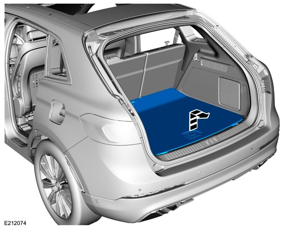
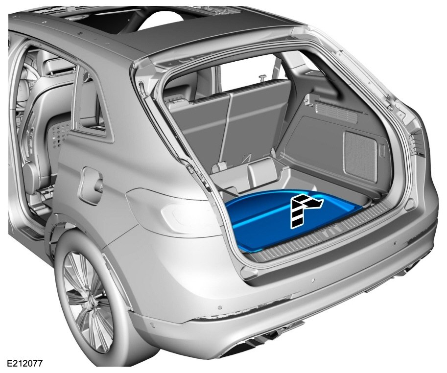
Have you tried removing the panel(s) you describe and taking a test drive, in order to confirm or eliminate it as the source of the noise/vibration/harshness? From the 2016 Edge Workshop Manual... Remove the load compartment floor cover. If equipped: Remove the spare tire cover. Good luck!


-
SSM 52127 2024 Nautilus - Infotainment - Switching From Transport To Normal Mode - No AM, FM Audio Playback And/Or Black Center Display Screen And Right Side Infotainment Display Some 2024 Nautilus vehicles may exhibit no audio playback from the AM, FM radio stations and/or a black center display screen and right side infotainment display when the vehicle is transitioned from transport to normal mode. When the audio volume control knob is rotated, the center display screen may or may not show visual change with no change in audio volume. To correct the condition, perform a manual SYNC module (APIM) reset. Press and hold the audio volume control knob (located on top of the center console) for 10-seconds and release the button - appearance of the welcome animation is an indication that the audio system is resetting. This condition does not affect vehicle durability and no additional diagnosis or service is required for this condition at this time. Make sure the issue is resolved before releasing the vehicle to the customer. SSM 52126 2024 Nautilus FHEV - DTC U053B:86 Setting In The SOBDMC When A Diagnostic Self-Test Is Performed Some 2024 Nautilus full hybrid electric vehicles (FHEV) may set a diagnostic trouble code (DTC) U053B:86 in the secondary on-board diagnostic control module C (SOBDMC) when a diagnostic self-test is performed. This may be due to a communication error between the image processing module A (IPMA) and SOBDMC. Replacement or reprogramming of the IPMA and/or SOBDMC will not resolve this condition. U053B:86 should be ignored and no further service action is required if no other DTCs are present in the IPMA and/or SOBDMC, the IPMA is configured correctly, no warning indicators are illuminated while the engine is running, and no symptoms present. SSM 52125 2024 Nautilus - DTC U3000:49 Setting In The CMR When A Diagnostic Self-Test Is Performed Some 2024 Nautilus vehicles may exhibit diagnostic trouble code (DTC) U3000:49 in the camera module-rear (CMR) when a diagnostic self-test is performed. This may be due to the system triggering a shared variable and then enters a timeout reset process. The history state DTC U3000:49 has no effect on functionality. Replacement or reprogramming of the CMR will not resolve this condition. Engineering is currently working on a solution and a software update is expected in Q2 2024. Continue to monitor OASIS for additional information. SSM 52124 2024 Nautilus - DTC B1578:89 Setting In The IPMA When A Diagnostic Self-Test Is Performed Some 2024 Nautilus vehicles may exhibit diagnostic trouble code (DTC) B1578:89 in the image processing module A (IPMA) when a diagnostic self-test is performed. This may be due to an internal module chip reboot that will recover by itself. B1578:89 has no effect on functionality. Replacement or reprogramming of the IPMA will not resolve this condition. Engineering is currently working on a solution and a software update is expected in Q2 2024. Continue to monitor OASIS for additional information. SSM 52120 2024 Nautilus - DTC U0422:00 Setting In The AWD Module When A Diagnostic Self-Test Is Performed Some 2024 Nautilus vehicles may set diagnostic trouble code (DTC) U0422:00 in the all-wheel drive (AWD) module when a diagnostic self-test is performed. This may be due to a communication error between the body control module (BCM) and AWD module. Replacement or reprogramming of the BCM and/or AWD module will not resolve this condition. U0422:00 should be ignored and no further service action is required if no other DTCs are present in the BCM and/or AWD module, the BCM is configured correctly, no warning indicators are illuminated while the engine is running, and no symptoms present. SSM 52119 2024 Nautilus - DTC U211B:87 Setting In The RFA Module When A Diagnostic Self-Test Is Performed Some 2024 Nautilus vehicles may set diagnostic trouble code (DTC) U211B:87 in the remote function actuator (RFA) module when a diagnostic self-test is performed. This may be due to an internal counter reaching a specified limit. U211B:87 has no effect on functionality and will automatically become a historical DTC which can be cleared. Replacement or reprogramming of the RFA module will not resolve this condition. U211B:87 should be ignored and no further service action is required if no other DTCs are present in the RFA, no warning indicators are illuminated while the engine is running, and no symptoms present. SSM 52118 2024 Nautilus - DTC U211B:87 Setting In The ABS Module When A Diagnostic Self-Test Is Performed Some 2024 Nautilus vehicles may exhibit diagnostic trouble code (DTC) U211B:87 in the anti-lock brake system (ABS) module when a diagnostic self-test is performed. This may be due to a module communication error within a specified timeframe. U211B:87 has no effect on functionality and will automatically become a historical DTC which can be cleared. Replacement or reprogramming of the ABS module will not resolve this condition. Engineering is currently working on a software update which is expected in Q1 2024. Continue to monitor OASIS for additional information. SSM 52117 2024 Nautilus - DTC B00DF:4A Setting In The RCM When A Diagnostic Self-Test Is Performed Some 2024 Nautilus vehicles may exhibit diagnostic trouble code (DTC) B00DF:4A in the restraints control module (RCM) when a diagnostic self-test is performed. This may be due to an internal counter reaching a specified timeframe. B00DF:4A has no effect on functionality. Replacement or reprogramming of the RCM will not resolve this condition. Inform customers that engineering is currently working on a solution for this condition and will be released via Ford Power-Up software updates delivered over-the-air (OTA) expected in Q3 2024. Software will update automatically if vehicle connectivity is enabled in the vehicle's settings. Schedule a service visit for customers who have disabled vehicle connectivity or who report that they did not receive the update in Q3 2024. Monitor OASIS for additional information. SSM 52116 2024 Nautilus - DTC B146F:04 Setting In The SCMG And/Or SCMH When A Diagnostic Self-Test Is Performed Some 2024 Nautilus vehicles may set diagnostic trouble code (DTC) B146F:00 in the drivers multi-contour seat module (SCMG) and/or passenger multi-contour seat module (SCMH) when a diagnostic self-test is performed. This may be due to a communication error to the SCMG/SCMH within a specified timeframe. Replacement or reprogramming of the SCMG/SCMH will not resolve this condition. B146F:00 should be ignored and no further service action is required if no other DTCs are present in the SCMG/SCMH, no warning indicators are illuminated while the engine is running, and no symptoms present. SSM 52115 2023 F-Super Duty, 2023-2024 Expedition, 2024 Nautilus - Remote Start - No LED Confirmation From The Key Fob After A Remote Start Request 2023 F-Super Duty, 2023-2024 Expedition and 2024 Nautilus vehicles will exhibit no light emitting diode (LED) confirmation from the key fob indicating that the vehicle has remote started (or not remote started). Factory key fobs with remote start no longer contain a LED feedback indicator. Do not replace the key fob for this condition. This is a normal operating characteristic and no service action is necessary. SSM 52114 2024 Nautilus – DTC U0415:29 Setting In The PSCM When A Diagnostic Self-Test Is Performed Some 2024 Nautilus vehicles may set diagnostic trouble code (DTC) U0415:29 in the power steering control module (PSCM) when a diagnostic self-test is performed. This may be due to PSCM DTC sensitivity during vehicle key on/start-up. Replacement or reprogramming of the PSCM will not resolve this condition. U0415:29 should be ignored and no further service action is required if no other DTCs are present in the PSCM, no warning indicators are illuminated while the engine is running, and no symptoms present. SSM 52112 2023 E-Transit, 2024 Nautilus - Diagnostic Trouble Codes (DTCS) C0095:18 And/Or C05D9:74 Setting In The AWD Module Some 2023 E-Transit and 2024 Nautilus vehicles may exhibit DTCs C0095:18 and/or C05D9:74 setting in the all-wheel drive (AWD) module with a pop-up message in the instrument panel cluster (IPC) stating there is a loss of AWD. The loss of AWD function may continue for the remainder of the key cycle. AWD functionally may be recovered with a key cycle. Replacement or reprogramming of the AWD module will not resolve this condition. This DTC does not affect vehicle durability and no additional diagnosis or service is required for this condition at this time. Inform customers that they can continue to drive the vehicle and engineering is currently working on a solution for this condition that is expected in Q2 2024. Monitor OASIS for additional information and schedule service appointments for customers once the repair becomes available. SSM 52111 2024 Nautilus - DTC U3001:68 Setting In The PSCM When A Diagnostic Self-Test Is Performed Some 2024 Nautilus vehicles may set diagnostic trouble code (DTC) U3001:68 in the power steering control module (PSCM) when a diagnostic self-test is performed. This may be due to an internal counter reaching a specified limit. U3001:68 has no effect on functionality and will automatically become a historical DTC which can be cleared. Replacement or reprogramming of the PSCM module will not resolve this condition. Engineering is currently working on a software update which is expected in Q1 2024. Continue to monitor OASIS for additional information. SSM 52110 2024 Nautilus - HVAC - Temperature Settings Inaccurate When Using Voice Commands Some 2024 Nautilus vehicles may exhibit inaccurate temperatures on the center display screen when requesting a temperature change using voice commands. Setting temperature and display can still be accurately increased/decreased by adjusting the touch controls. This may be due to a software interaction between the heating, ventilation and air conditioning (HVAC) module and SYNC module (APIM). Inform customers that engineering is currently working on a solution for this condition and will be released via Ford Power-Up software updates delivered over-the-air (OTA) expected in Q2 2024. Software will update automatically if vehicle connectivity is enabled in the vehicle's settings. Schedule a service visit for customers who have disabled vehicle connectivity or who report that they did not receive the update in Q2 2024. Monitor OASIS for additional information. SSM 52109 2024 Nautilus - DTC U211C:04 Setting In The GWM When A Diagnostic Self-Test Is Performed Some 2024 Nautilus vehicles may set diagnostic trouble code (DTC) U211C:04 in the gateway module A (GWM) when a diagnostic self-test is performed. This may be due to a module communication error within a specified timeframe. DTC U211C:04 has no effect on functionality and will automatically become a historical DTC which can be cleared. Replacement or reprogramming of the GWM will not resolve this condition. Engineering is currently working on a software update which is expected in Q1 2024. Continue to monitor OASIS for additional information. SSM 52108 2024 Nautilus FHEV - DTC B1465:08 And B1466:08 Setting In The BCMB When A Diagnostic Self-Test Is Performed Some 2024 Nautilus full hybrid electric vehicles (FHEV) may exhibit diagnostic trouble code (DTC) B1465:08 and B1466:08 in the body control module B (BCMB) when a diagnostic self-test is performed. This may be due to the ambient lighting node not transmitting feedback information within a specified timeframe. Replacement or reprogramming of the BCMB will not resolve this condition. The history state DTC B1465:08 and B1466:08 should be ignored and no further service action is required if no other DTCs are present in the BCMB, the BCMB is configured correctly, no warning indicators are illuminated while the engine is running, and no symptoms present.
-
2007 Ford Edge hvac, actuator, heater core Desperate
Haz replied to Ekim's topic in Interior, A.C., Heat, Interior Trim
Welcome to the Forum, kecusc ! Document download links> Control Components - Climate Control Systems - Description and Operation - 2008 Edge Workshop Manual.pdf Climate Control - Temperature Blend Door Actuator — LH - Removal and Installation - 2008 Edge Workshop Manual.pdf Temperature Blend Door Actuator — LH - Enhanced Image #1 - 2008 Edge Workshop Manual.pdf Temperature Blend Door Actuator — LH - Enhanced Image #2 - 2008 Edge Workshop Manual.pdf Good luck!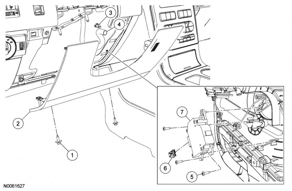

-
Document download link> Image Processing Module B (IPMB) - Removal and Installation - 2016 Edge Workshop Manual.pdf Good luck!
-
2016 Titanium - Low beam not working
Haz replied to Sunil's topic in Glass, Lenses, Lighting, Mirrors, Sunroof (BAMR), Wipers
Since only Low Beams, then it may be worth checking if a nearby national-brand auto parts store is willing to scan your Edge for headlamp-related DTCs, which may show wiring/connector issues versus FET-related BCM replacement need. Good luck! -
2016 Titanium - Low beam not working
Haz replied to Sunil's topic in Glass, Lenses, Lighting, Mirrors, Sunroof (BAMR), Wipers
Welcome to the Forum, Sunil ! From the 2016 Edge Workshop Manual... Low Beams The BCM monitors the headlamp switch position by sending voltage signals on multiple circuits to the headlamp switch. There is one circuit for each headlamp switch position. At any given time, one of the signal circuits is switched to ground to indicate the headlamp switch position. The BCM turns the parking lamps and headlamps on when the ignition is in RUN and the BCM detects a fault from the headlamp switch or wiring. This is normal behavior of the BCM when a fault has been detected with the inputs from the headlamp switch. When the BCM receives a message requesting the headlamps on, it supplies voltage to the headlamp bulbs (halogen headlamps) or the ballasts (High Intensity Discharge (HID) headlamps) within each headlamp assembly. Vehicles with High Intensity Discharge (HID) headlamps utilize a ballast, mounted to each headlamp assembly, to provide the necessary voltage to illuminate the High Intensity Discharge (HID) bulbs. The BCM also provides Field Effect Transistor (FET) protection of the exterior lamps switched voltage and low beam output circuits. When an excessive current draw is detected, the BCM disables the affected circuit driver. Field Effect Transistor (FET) Protection The BCM utilizes an Field Effect Transistor (FET) protective circuit strategy for many of its outputs, for example, lamp output circuits. Output loads (current level) are monitored for excessive current (typically short circuits) and are shut down (turns off the voltage or ground provided by the module) when a fault event is detected. A Field Effect Transistor (FET) is a type of transistor that the control module software uses to control and monitor current flow on module outputs. The Field Effect Transistor (FET) protection strategy prevents module damage in the event of excessive current flow. Output loads (current level) are monitored for excessive current draw (typically short circuits). When a fault event is detected the Field Effect Transistor (FET) turns off and a short circuit DTC sets. The module resets the Field Effect Transistor (FET) protection and allows the circuit to function when the fault is corrected or the ignition state is cycled off and then back on. When the excessive circuit load occurs often enough, the module shuts down the output until a repair procedure is carried out. Each Field Effect Transistor (FET) protected circuit has 3 predefined levels of short circuit tolerance based on a module lifetime level of fault events based upon the durability of the Field Effect Transistor (FET). If the total tolerance level is determined to be 600 fault events, the 3 predefined levels would be 200, 400 and 600 fault events. When each level is reached, the DTC associated with the short circuit sets along with DTC U1000:00. These Diagnostic Trouble Codes (DTCs) can be cleared using the module on-demand self-test, then the Clear DTC operation on the scan tool (if the on-demand test shows the fault corrected). The module never resets the fault event counter to zero and continues to advance the fault event counter as short circuit fault events occur. If the number of short circuit fault events reach the third level, then Diagnostic Trouble Codes (DTCs) U1000:00 and U3000:49 set along with the associated short circuit DTC . DTC U3000:49 cannot be cleared and the module must be replaced after the repair. One Or Both Low Beams is Inoperative DTC Fault Trigger Conditions DTC Description Fault Trigger Conditions B1D00:11 Left Low Beam: Circuit Short To Ground A continuous memory and on-demand DTC that sets when the BCM detects a short to ground from the LH low beam output circuit. B1D00:15 Left Low Beam: Circuit Short To Battery Or Open A continuous memory and on-demand DTC that sets when the BCM detects an open from the LH low beam output circuit. B1D01:11 Right Low Beam: Circuit Short To Ground A continuous memory and on-demand DTC that sets when the BCM detects a short to ground from the RH low beam output circuit. B1D01:15 Right Low Beam: Circuit Short To Battery Or Open A continuous memory and on-demand DTC that sets when the BCM detects an open from the RH low beam output circuit. U1000:00 Solid State Driver Protection Active -Driver Disabled: No Sub Type Information This DTC sets when the BCM has temporarily shut down the output driver. The module has temporarily disabled an output because an excessive current draw exists (such as a short to ground). The BCM cannot enable the output until the cause of the short is corrected, the Diagnostic Trouble Codes (DTCs) have been cleared and a successful self-test is run. For additional information on BCM Field Effect Transistor (FET) protection, REFER to: Module Controlled Functions - System Operation and Component Description (419-10 Multifunction Electronic Modules, Description and Operation). U3000:49 Control Module: Internal Electronic Failure This DTC sets when the BCM has permanently shut down the output driver. The module has permanently disabled an output because an excessive current draw fault (such as a short to ground) has exceeded the limits that the BCM can withstand. CORRECT the cause of the excessive current draw before installing a new BCM . For additional information on BCM Field Effect Transistor (FET) protection, REFER to: Module Controlled Functions - System Operation and Component Description (419-10 Multifunction Electronic Modules, Description and Operation). Possible Sources Fuse Wiring, terminals or connectors Bulb Ballast (High Intensity Discharge (HID) headlamps) Headlamp assembly BCM Visual Inspection and Diagnostic Pre-checks Inspect the headlamp assembly for damage. Inspect BJB fuse 44 (20A). Document download links> Headlamps - Wiring Diagram - 2016 Edge.pdf Battery Junction Box (BJB) - Location Illustration - 2016 Edge.pdf Battery Junction Box (BJB) - Top View - 2016 Edge.pdf Battery Junction Box (BJB) - Top View Legend - 2016 Edge.pdf Battery Junction Box (BJB) - Bottom View - 2016 Edge.pdf Battery Junction Box (BJB) - Bottom View Legend - 2016 Edge.pdf Good luck! -
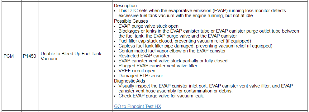
From... Document download links> Evaporative Emission (EVAP) Systems - Description and Operation - 2016 Gasoline - PC-ED Manual.pdf Evaporative Emission (EVAP) Systems - Enlarged System Illustration - 2016 Gasoline - PC-ED Manual.pdf PINPOINT TEST HX - EVAPORATIVE EMISSION (EVAP) SYSTEM AND MONITOR - 2016 Gasoline - PC-ED Manual.pdf EVAPORATIVE EMISSION (EVAP) PURGE VALVE - Connector C1196 Details - 2016 Edge.pdf PINPOINT TEST Z - INTERMITTENT PROBLEMS - 2016 Gasoline - PC-ED Manual.pdf Clear The Continuous Diagnostic Trouble Codes (DTCs) And Reset The Emission Monitors Information In The Powertrain Control Module (PCM) - Diagnostic Methods - 2016 Gasoline - PC-ED Manual.pdf On Board Diagnostic (OBD) Drive Cycle - Diagnostic Methods - 2016 Gasoline - PC-ED Manual.pdf Good luck!
-
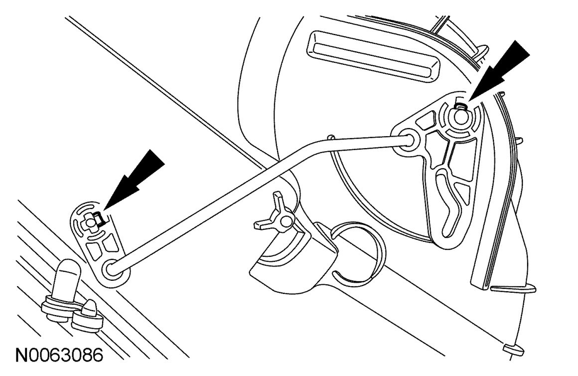
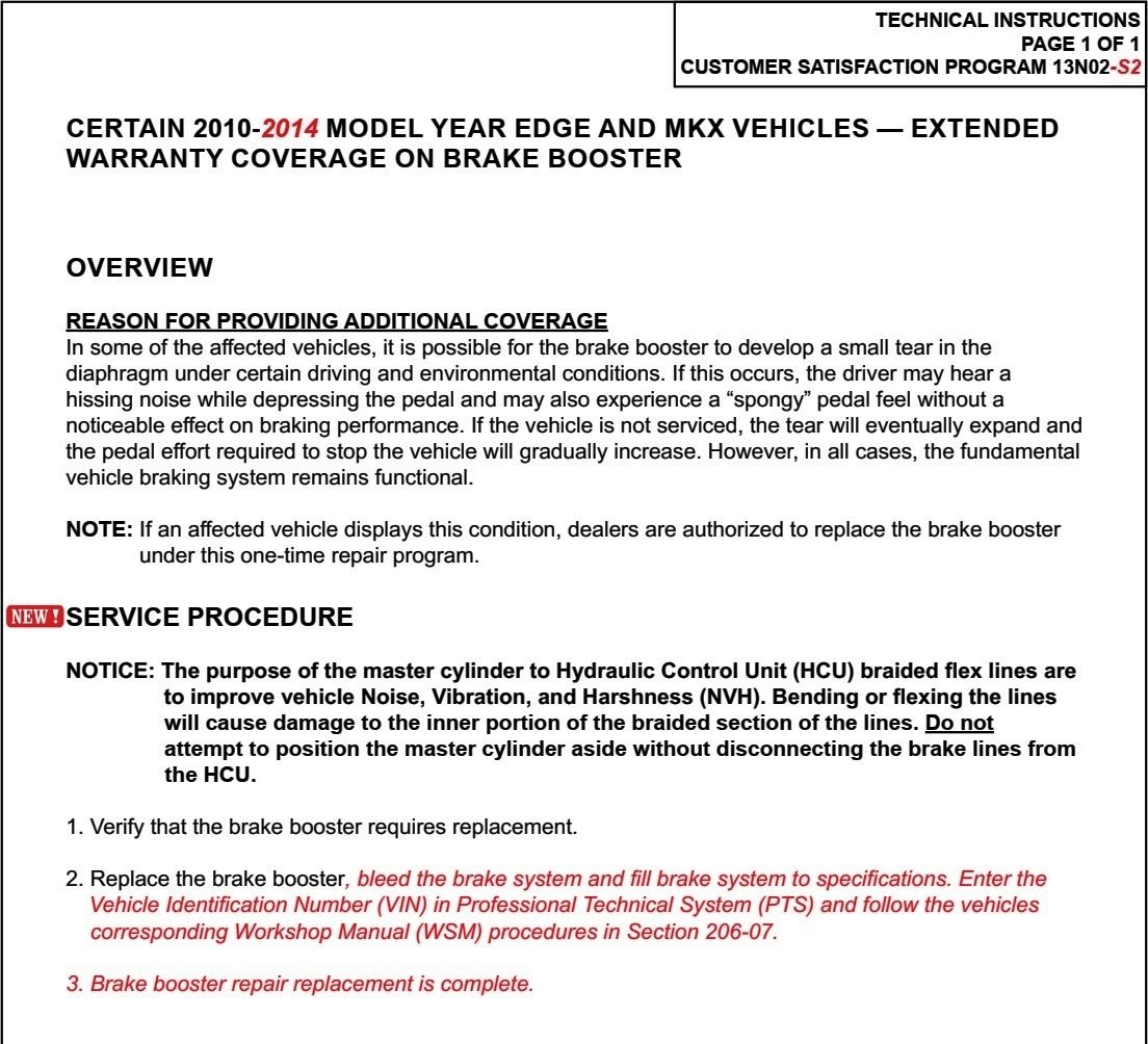
13N02 - Extended Warranty Coverage on Brake Booster
Haz replied to omar302's topic in Recalls, TSBs & Warranty
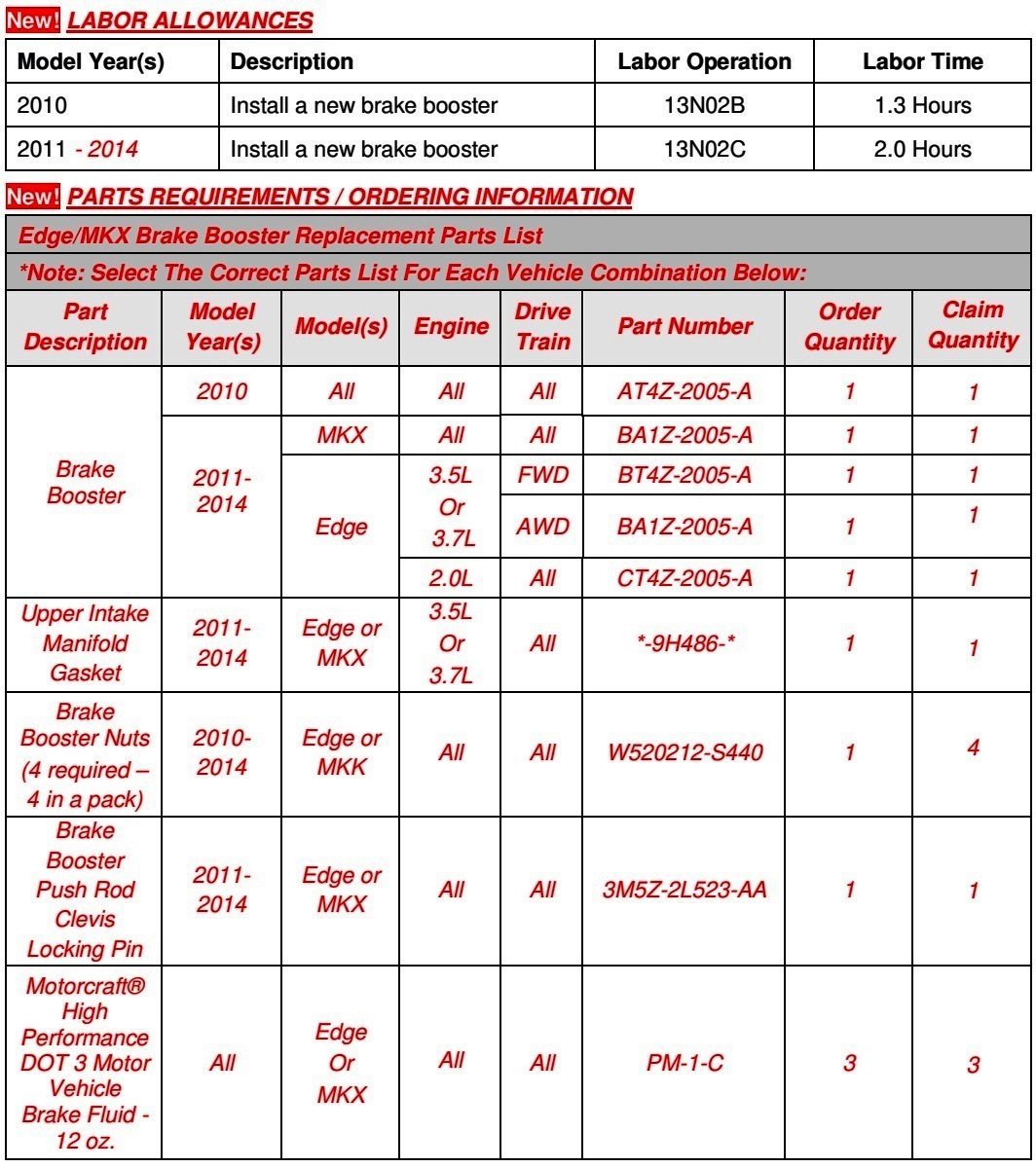
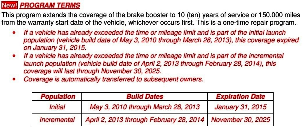
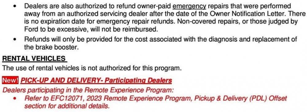
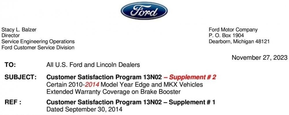
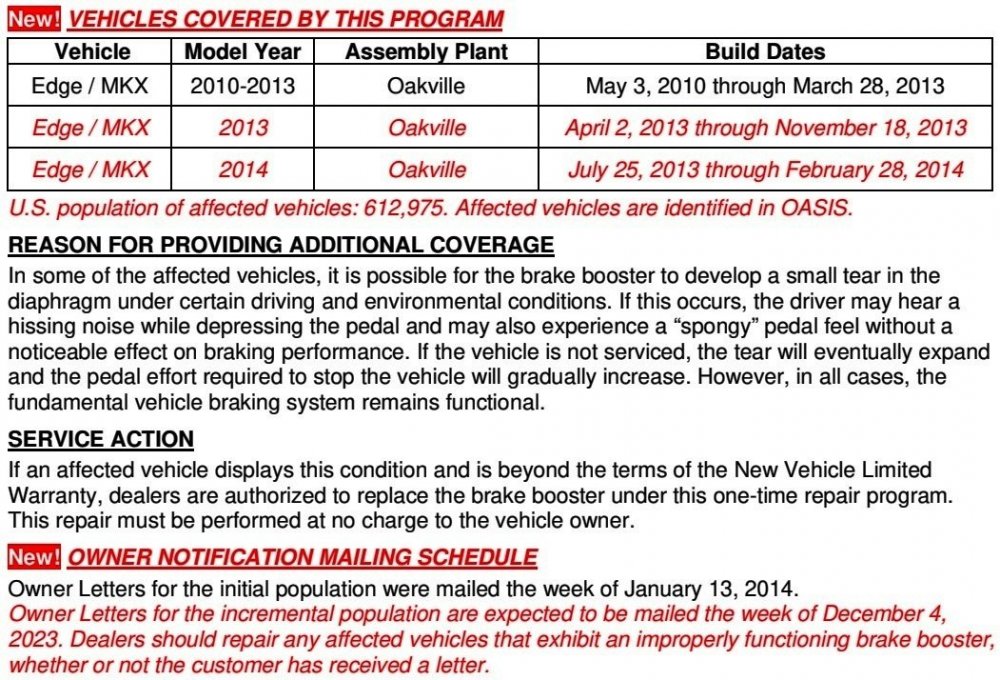
Program 13N02's Brake Booster warranty extension coverage has been incrementally expanded to a larger population of 2013-2014 Edge/MKX vehicles and a Refund program for owner-paid Brake Booster replacements to vehicles in the expanded population is available through December 31, 2023. For full information, see... Customer Satisfaction Program 13N02, Supplement # 2 - Certain 2010-2014 Model Year Edge and MKX Vehicles - Extended Warranty Coverage on Brake Booster (10 Year/150,000 miles) Good luck! -
Supplement #2 Highlights Eligibility expanded to additional 2013 & 2014 Edge/MKX vehicles; Refunds for past owner-paid repairs to expanded vehicle population available through December 31, 2023 expiration date. Document download links to Notification Letter examples being sent to Owners of the incrementally expanded population of Edge & MKX vehicles> Customer Satisfaction Program 13N02 Supplement #2 - Ford Owner Letter - 11-27-2023.pdf Customer Satisfaction Program 13N02 Supplement #2 - Lincoln Owner Letter - 11-27-2023.pdf Link to original Forum post on Field Service Action 13N02 and extensive discussion on Forum member 13N02/Brake Booster experiences


-
denny73: No differences between U.K. and Italy editions of the posted documents. Additional document download link> Rear Drive Axle and Differential - 2.0L EcoBlue - System Operation and Component Description - 2015 - 2022 Edge, Edge Vignale, Endura Workshop Manual.pdf Good luck!
-
The U.K. edition of Ford's Professional Technician System (PTS) website does not show any SSM relating to reprogramming the AWD module, per the above SSM, however it does show TSB 23-2290 covering potential RDU fluid contamination, which was released on the U.K. PTS site before a comparable U.S. SSM 52051, shown in this Forum post that you may also want to look at... Special Service Message 52051 - 2019-2023 Edge/Nautilus + Maverick - AWD - Chatter/Shudder During Low Speed Turning Events U.K Edition document download links> TSB 23-2290 - Chatter-Shudder during low speed turning events - Effective 09-2023.pdf Differential Level Check - General Procedures - 2015 - 2022 Edge, Edge Vignale, Endura Workshop Manual.pdf If you're not the U.K, which EU country represents your Ford vehicle market area? If any differences exist where you reside, I will post further information. Good luck!
-
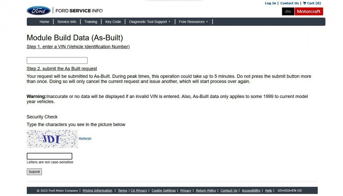
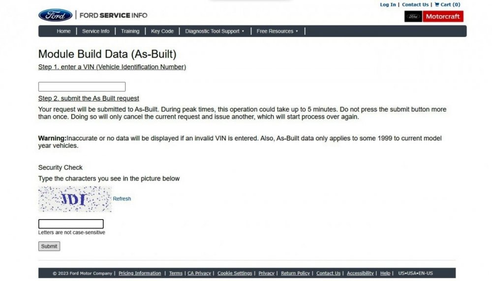
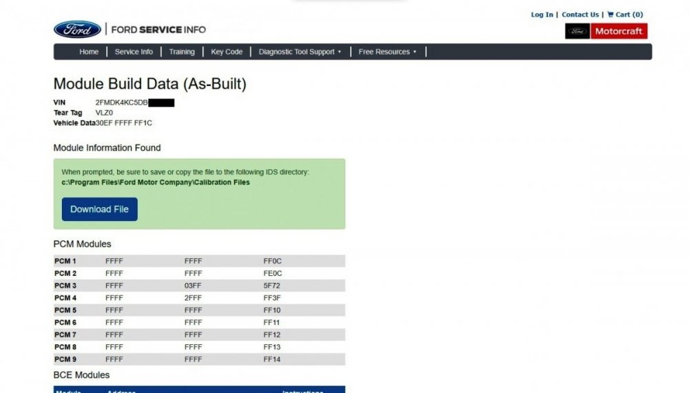
danwdc: You're correct that the Dorman replacement Cruise Control Module (CCM) you installed needs to be programmed with the same As-Built data that was contained in the original CCM you removed. If you did not save those values from the original CCM before removing it, you can use the Ford Service Info website to review and/or save the entire set of As-Built data values for the electronic modules in your 2013 Edge Limited AWD, and then use a temporary-licensed or fully-licensed copy of Forscan to manually program the Dorman replacement CCM using the address 764-01-01 As-Built values and then save them to the installed Dorman replacement CCM. As omar302 advises, go to https://www.motorcraftservice.com/AsBuilt, and after selecting your Country/Language, submit the form... ...input your Edge's VIN and the Security Check captcha value and submit the second form... ...and the resulting As-Built Report for your Edge allows you to Download File an .AB electronic data file that includes the electronic programming for all modules, and the web page provides the same complete data set in text format for you to print for visual reference... I surveyed Cruise Control Module As-Built data for ten 2013 Edge Limited AWD vehicles offered for sale online, and I found two different programming values in use... ...so it is absolutely necessary for you to obtain CCM As -Built data by submitting your Edge's VIN to the Ford Service Info website. Forscan probably shows this Diagnostic Trouble Code (DTC) in the CCM, which you will want to clear if it remains after performing a CCM Self Test after programming the Dorman replacement CCM... U2100:00 Initial Configuration Not Complete: No Sub Type Information Document download link> Module Configuration - Diagnosis and Testing - 2013 Edge Workshop Manual.pdf Good luck!


-
If you are seeing the following message after clicking on a download link, it may be due to you not being signed-in as a Forum member... The above document download links are currently active and, to the best of my knowledge, should be available to any signed-in Forum member. Good luck!