


Haz
-
Posts
1,476 -
Joined
-
Last visited
-
Days Won
395
Content Type
Profiles
Forums
Gallery
Everything posted by Haz
-
2016 Edge Sport Alternator Job - Anyone have details?
Haz replied to Cerberus's topic in 2016 Edge & MKX
Document download links> Generator - 2.7L EcoBoost - Removal and Installation - 2016 Edge Workshop Manual.pdf Air Conditioning Compressor - 2.7L EcoBoost - Removal and Installation - 2016 Edge Workshop Manual.pdf Please note that several of the numbered action-step descriptions appear on the page prior to the illustration to which they apply, due to formatting for maximum illustration size. Go Vols ! -
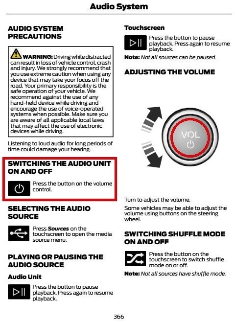
How to turn radio off and back on..
Haz replied to Termin8r's topic in Audio, Backup, Navigation & SYNC
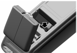
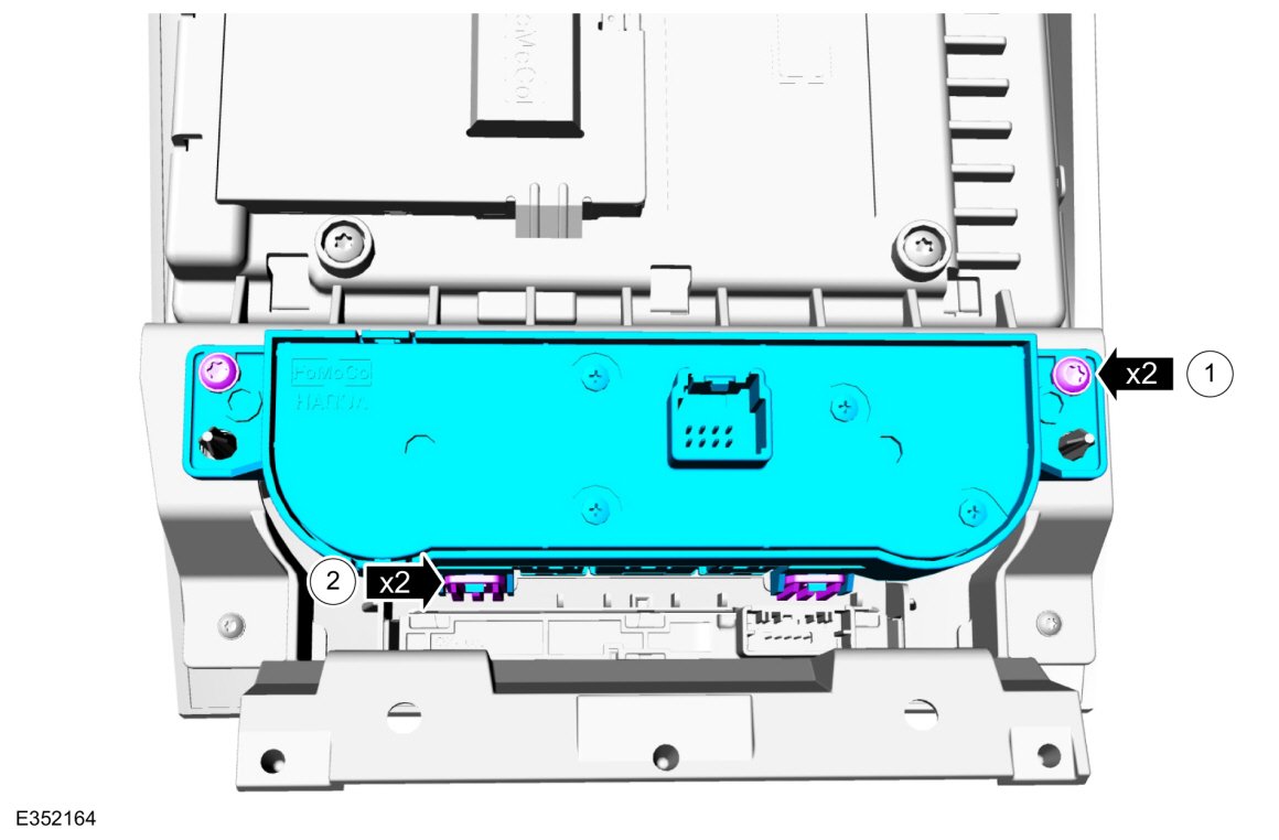
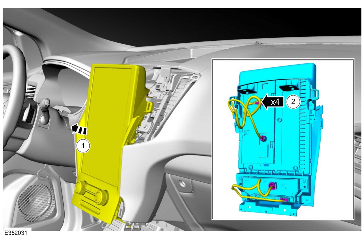
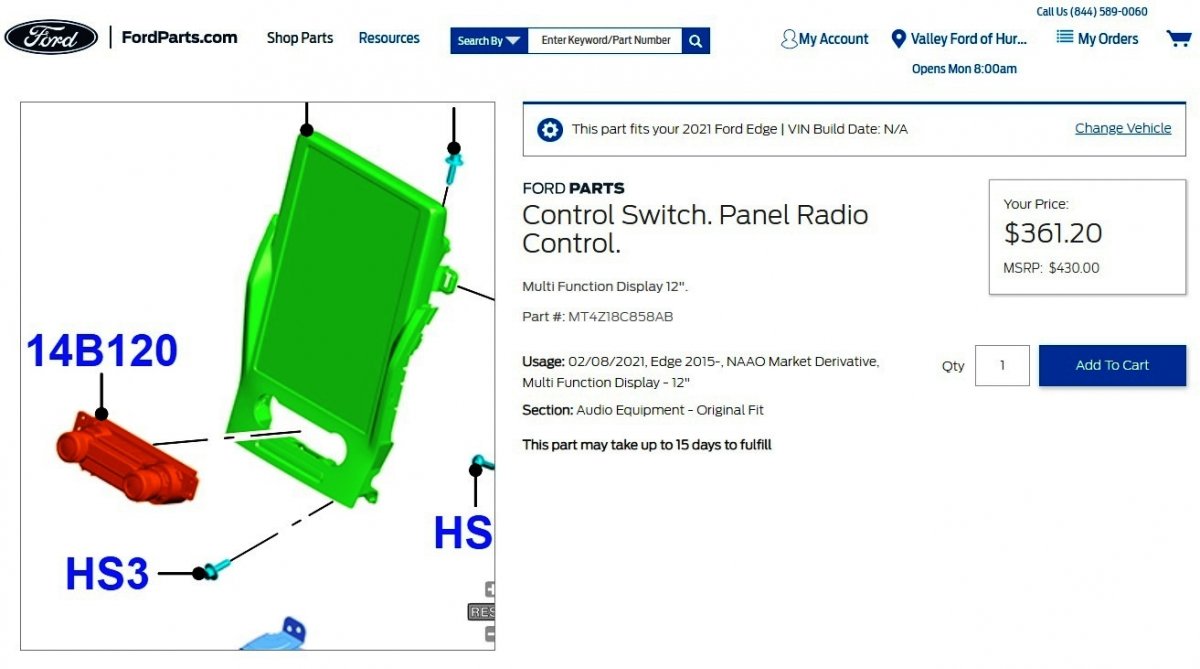
Welcome to the Forum, Termin8r ! As others have mentioned, from the 2021 Edge Owner's Manual... If the power switch function of the left control knob is faulty, the Radio Control Switch Panel is replaceable separate from the Display Screen... Document download links> Audio Controls - Removal and Installation - 2021 Edge Workshop Manual.pdf Floor Console - Removal and Installation - 2021 Edge Workshop Manual.pdf Good luck!


-
From the 2012 Edge Workshop Manual... Battery Management System Load Shed Strategy NOTICE: When any vehicle module is being programmed, connect an external battery charger to make sure that the module programming is completed without the interruption due to the load shedding feature becoming active. The external battery charger must maintain a system voltage above 13 volts. This can require a charger setting higher than the lowest charge setting. The external battery charger negative connection must be made to an engine or vehicle chassis ground and not the negative battery terminal. If the connection is to the negative battery terminal, load shedding cannot be prevented from being invoked and module programming may be corrupted. After charging has begun, start the engine to clear any load shed states and then turn the engine off and proceed with programming. NOTE: To maintain correct operation of the load shed, any electrical devices or equipment must be grounded to the chassis ground and not the negative battery terminal. A connection to the negative battery terminal can cause an inaccurate measurement of the battery state of charge and can cause incorrect load shed system operation. This vehicle is equipped with a load shed strategy. The Body Control Module (BCM) uses the battery current sensor to keep track of the battery state of charge. The battery current sensor is a Hall-effect sensor attached to the battery ground cable. On vehicles equipped with Intelligent Access (IA) , the ignition state can also change. Engine Off Load Shed The BCM uses the battery current sensor to keep track of the battery state of charge. The battery current sensor is a Hall-effect sensor attached to the battery ground cable. When the engine is off, and the BCM determines the battery state of charge is below 40%, 10% of the charge has been drained or 45 minutes have elapsed, a load shed message is sent over the Controller Area Network (CAN) . This message turns off the audio system to save the remaining battery charge. Under this condition, a message may be displayed on the IPC or center stack display to alert the driver that battery protection actions are active. When charging the vehicle battery by connecting the charger to the negative battery terminal is necessary, such as when using a combination battery charger and battery tester/analyzer, like the GR 1 190 V3.0 Intelligent Diagnostic Charger, the BCM will not immediately update the battery state of charge. In this instance, after charging, you must CARRY OUT the Battery Monitoring System (BMS) Reset using the scan tool. This reset is needed for proper engine off load shedding and to prevent invoking of engine off load shedding earlier than normal. NOTE: If the reset is not carried out, when the battery is charged by connecting the charger to the negative battery terminal, it takes approximately 8 hours for the BCM to learn the new battery state of charge. During this 8 hour period, the vehicle must be undisturbed, with no doors opened or keyless entry button presses. If the vehicle is used before the BCM is allowed to learn the new battery state of charge, engine off load shedding can still occur and a message may be displayed. When charging the vehicle battery by connecting the charger to engine or chassis ground, the negative charger clamp must be connected to an unpainted chassis surface or a solid engine component such as a generator mount or engine lifting eye. In this instance, after charging, the BMS reset is not required if the ignition was ON during charging by above method. Through this method of charging, the BCM updates the battery state of charge during the charging process. If the ignition was OFF during charging by above method, a BMS reset may be required since the BCM does not update battery state of charge with ignition key OFF unless the vehicle is parked undisturbed for 8 hours. Document download link> Charging System - Diagnosis and Testing - 2012 Edge-MKX Workshop Manual.pdf Good luck!
-
This topic is being recommunicated as Special Service Message 52172, highlighting the 2024 Nautilus owner's ability to recover the Master Access Code, due to the absence of a keypad code card being provided with the vehicle at delivery... SSM 52172 2024 Nautilus - Keyless Entry Keypad Code Card Missing Some 2024 Nautilus vehicles may incorrectly list the keyless entry keypad code card on the loose item checklist. 2024 Nautilus vehicles in North America do not include keyless entry keypad code cards. Clients are now able to retrieve the vehicle's keyless entry keypad master access code in vehicle by following the instructions in the Owner's Manual > Keyless Entry Keypad Master Access Code. This process requires the use of two programmed intelligent access keys.
-
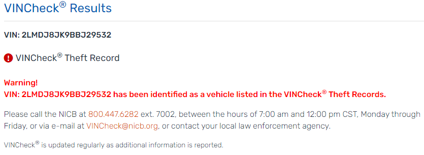
CARR142: Saddened to learn of your MKX's fate, but more fully saddened over you being stolen away from all of us. Please let us know what you replace the MKX with. Good luck! From https://www.nicb.org/vincheck

-
THIS GSB 23-7173 HAS BEEN SUPRECEDED BY GENERAL SERVICE BULLETIN 24-7133, WHICH IMMEDIATELY FOLLOWS... GENERAL SERVICE BULLETIN Various Vehicles - Rear-View Mirror Concern Analysis 23-7173 05 January 2024 This bulletin supersedes 23-7092. Summary This article supersedes GSB 23-7092 to add the Melted Housing section and update the power mirror synchronization. This article is designed to provide examples of interior and exterior rear-view mirror conditions/damage to assist in determining if the condition is warrantable or non-warrantable. Refer to the latest version of the Warranty and Policy Manual online for the latest rear-view mirror warranty coverage information. Use this article to assist in determining warrantable interior and exterior rear-view mirror concerns. Service Information Vehicles with power folding rear-view mirrors may exhibit concerns such as inoperative, folding with clicking sounds, vibrating/shaking in wind/while driving, or does not lock firmly in drive position. This may occur when the exterior rear-view mirrors are manually folded in such as going through a car wash, being bumped in transportation or a parking lot, or only one mirror is folded in. This may be attributed to the power folding mirror being out of synchronization or damage to the mirror mount. Perform the mirror synchronization procedure prior to completing any additional diagnostics. The synchronization procedure may need to be performed more than once to receive the loud popping sound, which is an indication the synchronization procedure has completed. Refer to WSM Section 501-09 Rear View Mirrors – General Procedures – Power Mirrors Synchronization. If the synchronization procedure does not correct the concern, continue with cleaning and inspection before performing additional diagnostics. Diagnostic test results and resynchronization information must be documented if a warrantable defect is found. Concerns that are corrected by the power mirror synchronization should not be submitted under warranty. Loose manual folding exterior rear-view mirrors are most commonly the result of damage to the assembly/mount. Closely inspect the exterior rear-view mirror after cleaning to review for witness marks/impact damage. Loose interior rear-view mirror mounts are most commonly the result of not being seated or the mount/attachment being damaged. Reseating the mirror per the WSM, Section 501-09 Rear View Mirrors may correct this concern. If the windshield has been replaced, damage to the mount can occur from improper removal/installation. Pen test A pen test should be used to determine mirror glass impact damage. Slowly run the tip of a ball point pen inside the crack throughout its entire length. If an impact is present, the pen helps to feel an impression. Cleaning procedure Clean the entire mirror assembly and glass to assist in verification of the customer concern and/or impact damage using water, a cloth, and car wash soap as needed. Do not clean any mirror glass or housing with an ice scraper, razor blade, abrasive pad, harsh chemicals or petroleum based cleaning products, as these may damage the mirror glass and/or housing. Examples Of Non-warrantable And Warrantable Conditions A rear-view mirror assembly can be damaged from abuse or impact and show little or no witness marks on housing. Shiny or flat spots on the housing indicate abuse or impact. Typical non-warrantable damage from abuse or impact Exterior mirror: • Mirror glass missing • Glass with scratches or cracks • Glass loose due to broken pivot or missing jackscrews • Scrapes on housing resulting from impact or abuse • Attachments loose due to impact • Broken mirror motor plate • Glass reattached (glued) after impact • Broken pivot neck/housing Interior mirror: • Interior mirror glass cracked • Broken windshield at mirror mount • Interior mirror detached pivot Typical warrantable conditions • Glass discoloration • Distorted mirror glass reflection • Electrical failure of motors and switches • Wiring harness shorted • Single line glass crack on heated mirror (verified with pen test) • Single line glass stress crack (verified with pen test) NOTE: All mirror components should be serviced at the lowest level available per the Warranty and Policy Manual. Over-repairs when lower-level components are available are subject to review and warranty adjustment. Dirty Mirror Housing (Non-warrantable) (Figure 1) Dirty mirror housings cannot be properly inspected for outside source influence. Mirrors returned without proper cleaning are subject to warranty review and adjustment. Figure 1 Scrapes, Impact, Broken Housing, Loose Attachment (Non-warrantable) (Figure 2) Figure 2 Power Folding Mirror Detent Pin Damage (Non-warrantable) (Figures 3-5) Power-fold trailer tow mirrors are designed to operate the mirror between home to folded position. They are also designed to manually fold forward beyond home position. If the mirror is forcefully pushed beyond the forward fold position, the detent pin in the mirror is damaged and will not stop at home position using the power-fold button. To test this, push the power-fold button. If the mirror unfolds forward past home position (using the power fold button), it is not warrantable. Figure 3 Figure 4 Figure 5 Grain Removed From Plastic Mirror Housing (Non-warrantable) (Figure 6) Physical damage that is often accompanied by power-fold mirror detent pin damage. Figure 6 Glass Loose, Broken Motor (Non-warrantable) (Figures 7-8) Figure 7 Missing mirror glass/backing plate missing (non-warrantable) (Figure 😎 Figure 8 Melted Housing (Non-warrantable) (Figures 9-10) Indicates exposure to excessive heat or chemical contact. Figure 9 Figure 10 Discolored Housing (Non-warrantable) (Figure 11) Stains may have a liquid drip or spray pattern (shown) from contact with harsh liquids. Figure 11 Discolored Glass (Warrantable) (Figure 12) Figure 12 Distorted Mirror Glass Reflection (Warrantable) (Figure 13) Figure 13 Single Line Crack On Heated Mirror (Warrantable) (Figure 14) This crack will occur from thermal stress. Refer to the pen test at the beginning of this article to determine impact damage. Figure 14 Distorted Puddle Lamp Projected Image (Warrantable) (Figure 15) Figure 15 Portion Of Missing Glass (Warrantable) (Figure 16) Adhesive is still present on the mirror backing plate which is securely attached to the motor. Figure 16 Interior Mirror Glass Cracked (Non-warrantable) (Figure 17) Excessive force including improper removal/installation. Figure 17 Broken Windshield (Non-warrantable) (Figure 18) Excessive force including improper removal/installation. Figure 18 Interior Mirror Detached Pivot (Non-warrantable) (Figure 19) Excessive force will detach the press fit pivots. Figure 19 Blocked Light Sensor (Non-warrantable) (Figure 20) Obstruction will cause inoperative automatic high beam. Figure 20 © 2024 Ford Motor Company All rights reserved. NOTE: This information is not intended to replace or supersede any warranty, parts and service policy, workshop manual (WSM) procedures or technical training or wiring diagram information.
- 1 reply
-
- 2
-

-
Remaining document download links> BATTERY JUNCTION BOX (BJB)-Windshield Wiper Motors-Rain Sensor - Wiring Diagram - 2018 Edge.pdf BATTERY JUNCTION BOX (BJB) - Top View Diagram - 2018 Edge.pdf BATTERY JUNCTION BOX (BJB) - Top View Diagram Legend - 2018 Edge.pdf BATTERY JUNCTION BOX (BJB) - Bottom View Diagram - 2018 Edge.pdf BATTERY JUNCTION BOX (BJB) - Bottom View Diagram Legend - 2018 Edge.pdf BODY CONTROL MODULE (BCM) - Diagram - 2018 Edge.pdf BODY CONTROL MODULE (BCM) - Diagram Legend - 2018 Edge.pdf Good luck!

-
Additional document download links> WINDSHIELD WIPER MOTOR LH - Ground C111 Location - 2018 Edge.pdf WINDSHIELD WIPER MOTOR RH - Ground G114 Location - 2018 Edge.pdf BATTERY JUNCTION BOX (BJB) - Connector C1035B Details - 2018 Edge.pdf BATTERY JUNCTION BOX (BJB) - Connector C1035A-B-C Location - 2018 Edge.pdf Rain Sensor - Connector C914 Details - 2018 Edge.pdf Rain Sensor - Connector C914 Location - 2018 Edge.pdf
-
Additional document download links> WINDSHIELD WIPER MOTOR LH - Connector C1655 Details - 2018 Edge.pdf WINDSHIELD WIPER MOTOR LH - Connector C1655 Location - 2018 Edge.pdf WINDSHIELD WIPER MOTOR RH - Connector C1656 Details - 2018 Edge.pdf WINDSHIELD WIPER MOTOR RH - Connector C1656 Location - 2018 Edge.pdf BODY CONTROL MODULE (BCM) - Connector C2280C Details - 2018 Edge.pdf BODY CONTROL MODULE (BCM) - Connector C2280C Location - 2018 Edge.pdf STEERING COLUMN CONTROL MODULE (SCCM) - Connector C226A Details - 2018 Edge.pdf STEERING COLUMN CONTROL MODULE (SCCM) - Connector C226A Location - 2018 Edge.pdf
-
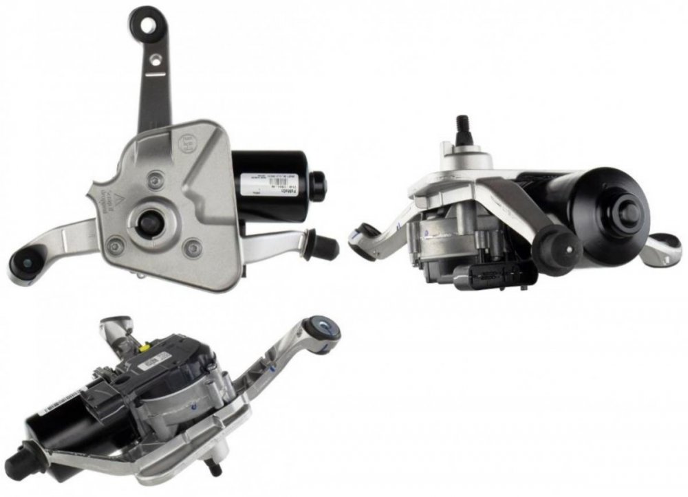
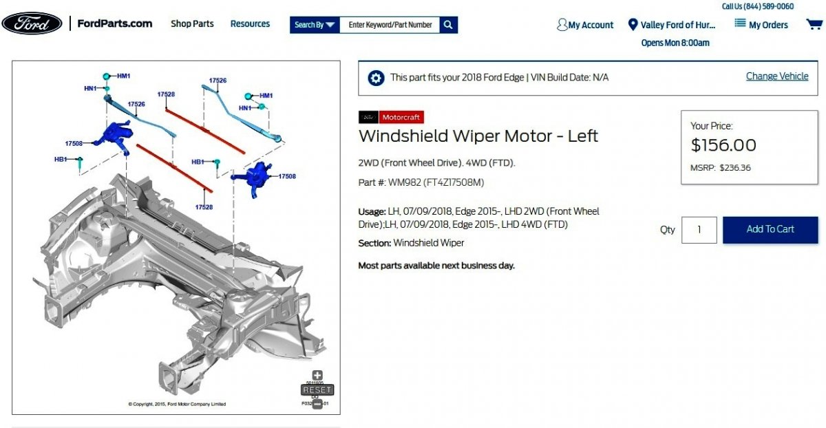
Welcome to the Forum, phillieeagle ! Having your Edge Sport scanned for Diagnostic Trouble Codes (DTCs) may reveal a cause of the left hand wiper motor symptoms. I did find this Special Service Message (SSM) describing intermittent wiper motor operation due to snow and ice blockage -- clearly not your Edge's issue, though repeated resistance to movement can lead to wiper motor replacement... SSM 48094 2015-2019 Edge Vehicles - Build On Or Before 5-Nov-2018 - Wipers Intermittent Operation Issues In Snow/Ice Conditions Some 2015-2019 Edge vehicles build on or before 5-Nov-2018 may exhibit snow and/or ice accumulation below the wiper blade park position, causing the wipers to have intermittent operational issues. If normal diagnostics do not result in a root cause determination, replace the driver’s side wiper motor with updated service part FT4Z-17508-H, and make sure the customer is advised to keep the cowl area clean of ice and snow. Refer to Workshop Manual (WSM), Section 501-16 and applicable labor operations in Section 11 of the Service Labor Time Standards (SLTS) Manual. Diagnostic and repair procedures are provided in this, and immediately following Forum posts, due to Forum attachment limitations... Document download links> Wipers and Washers - System Operation and Component Description - 2018 Edge Workshop Manual.pdf Wipers and Washers - Diagnosis and Testing - 2018 Edge Workshop Manual.pdf DIAGNOSTIC PINPOINT TEST G - THE WINDSHIELD WIPERS DO NOT PARK AT THE CORRECT POSITION - 2018 Edge Workshop Manual.pdf Windshield Wiper Pivot Arm - Removal and Installation - 2018 Edge Workshop Manual.pdf Windshield Wiper Motor - Wiring Diagram - 2018 Edge.pdf Cowl Panel Grille - Removal and Installation - 2018 Edge Workshop Manual.pdf Cowl Panel - Removal and Installation - 2018 Edge Workshop Manual.pdf Windshield Wiper Motor - Removal and Installation - 2018 Edge Workshop Manual.pdf
-
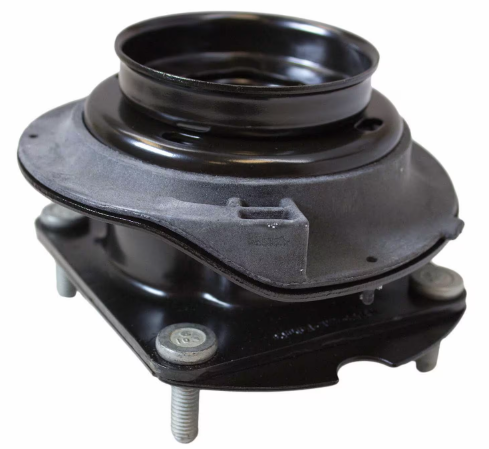
Struts and shocks, Motorcraft or KYB?
Haz replied to jonesboys310's topic in Brakes, Chassis & Suspension
Link to this FordParts webpage Document download links> Shock Absorber and Spring Assembly - Removal and Installation - 2014 Edge Workshop Manual.pdf Cowl Panel Grille - Removal and Installation - 2014 Edge Workshop Manual.pdf Shock Absorber and Spring Assembly - Disassembly and Assembly -2014 Edge Workshop Manual.pdf Good luck!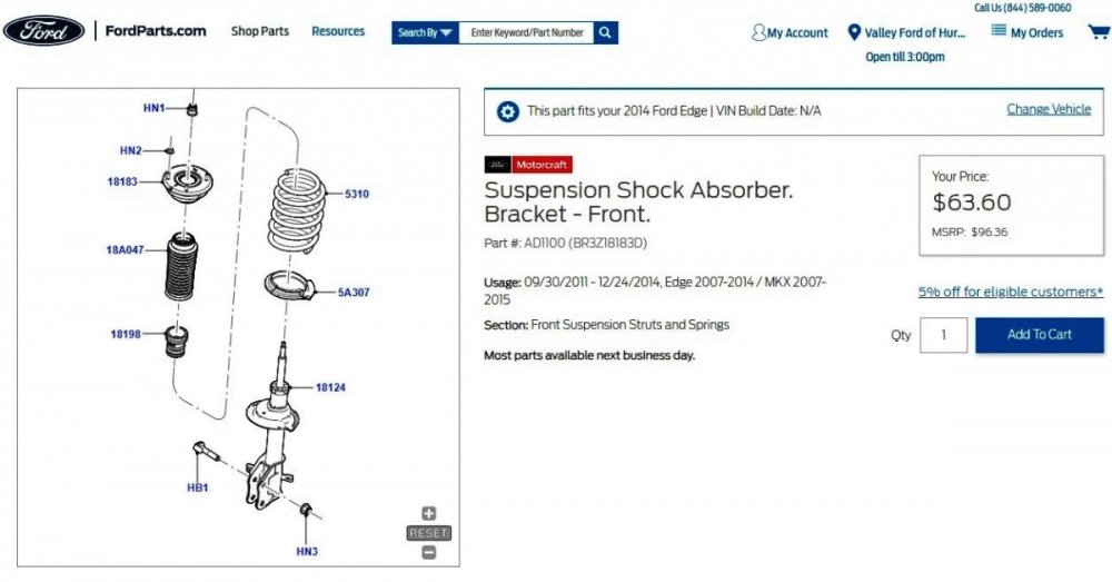
-
Factory installation instructions for 2015 Edge front bumper
Haz replied to Olwiseone's topic in Exterior & Body
Document download links> Front Bumper Cover - Removal and Installation - 2015 Edge Workshop Manual.pdf Front Bumper - Removal and Installation - 2015 Edge Workshop Manual.pdf Active Grille Shutter - Removal and Installation - 2015 Edge Workshop Manual.pdf Good luck! -
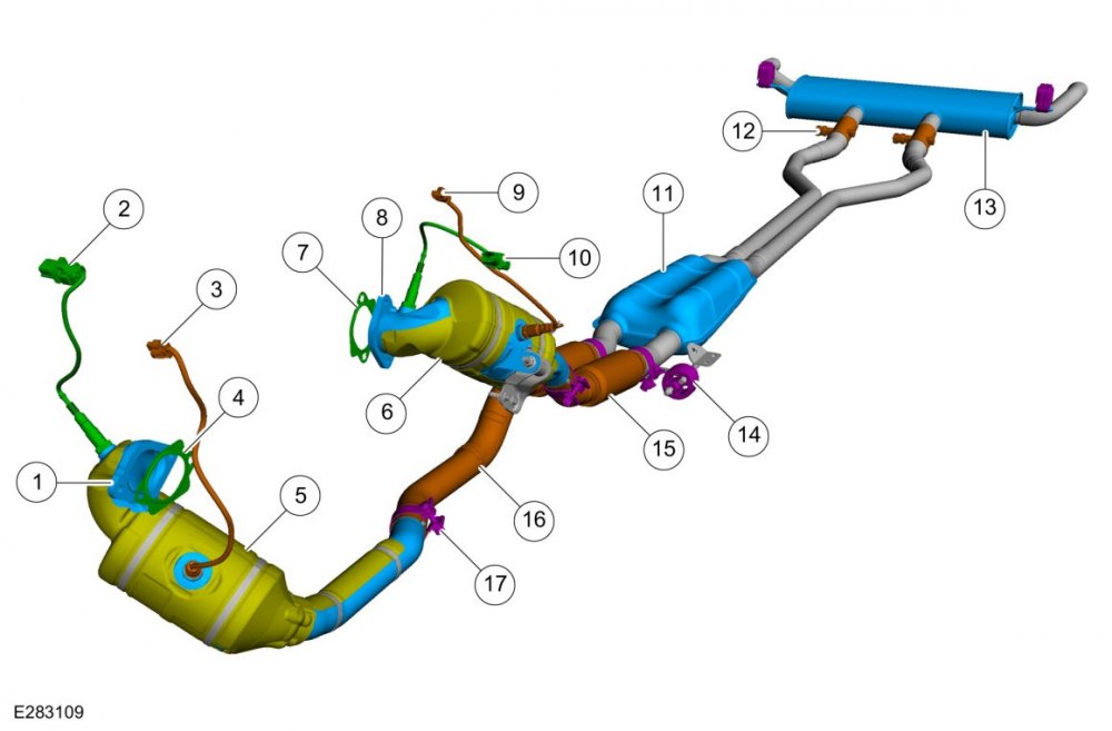
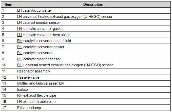
Document download link> Exhaust System - Component Location - 2.7L EcoBoost - 2019 Edge Workshop Manual.pdf Good luck!
-
Good luck!
-
From the 2019 Edge Workshop Manual... 309-00B Exhaust System - 2.7L EcoBoost (238kW/324PS) 2021 Edge Diagnosis and Testing Procedure revision date: 02/20/2020 Exhaust System Symptom Chart(s) Symptom Chart: Symptom Chart - Exhaust System Verify the customer concern. Inspect the components of the exhaust system for obvious signs of damage or other mechanical concerns using the following chart. Visual Inspection Chart - Mechanical Mechanical Exhaust pipe pinched or crushed Damaged muffler Broken or damaged exhaust hanger brackets Damaged catalytic converter Damaged exhaust passive valve Loose or damaged heat shields Verify the exhaust system is installed correctly, with clamps correctly located and tightened to specifications. If the fault is not visually evident, determine the symptom. GO to the Symptom Chart below. Symptom Chart: Symptom Chart - NVH Condition Possible Sources Actions Rattle, squeaks or buzz type noise — from the bottom of the vehicle Loose or damaged heat shield INSPECT the exhaust system for loose or missing heat shields or foreign material trapped between the heat shields and the exhaust system components. If any heat shields are loose, INSTALL worm gear clamp 7L5Z-5A231-AA and tighten to 7 Nm. If the heat shields are missing or a rattle, noise or buzz condition persists, INSTALL a new heat shield or component as necessary. Loose or damaged exhaust isolators VERIFY the exhaust isolators are correctly installed. INSPECT the exhaust isolators for wear or damage. INSTALL new isolators as necessary. Damaged exhaust isolator hanger bracket INSPECT the exhaust system components for damage or broken hangers. INSTALL new components as necessary. CHECK for loose or damaged exhaust hanger brackets or fasteners. TIGHTEN the bolts to specification or INSTALL new components as necessary. Loose or damaged catalytic converter or muffler MOVE the exhaust system to simulate the bouncing action of the vehicle, checking for exhaust-to-body contact while moving the exhaust system. Using a rubber mallet, TAP on the exhaust components to duplicate the noise concern. Lightly TAP on the muffler, then the catalytic converter. DETERMINE if there are loose or broken baffles in the muffler or a loose or broken element in the catalytic converter. REPAIR or INSTALL new components as necessary. Exhaust grounded to chassis INSPECT for signs of exhaust components-to-body contact. REPAIR or INSTALL new components as necessary. Exhaust passive valve INSPECT the operation of the exhaust passive valve. REPAIR or INSTALL new components as necessary. Drone or clunk type noise — from the bottom of the vehicle Loose or damaged exhaust isolators INSPECT the exhaust isolators for wear or damage. INSTALL new isolators as necessary. Exhaust grounded to chassis INSPECT for signs of exhaust components-to-body contact. REPAIR or INSTALL new components as necessary. Whistles, boom, hum or ticking type noise — noise tends to change as the engine warms. The noises are often accompanied by exhaust fumes Exhaust system leak INSPECT the entire exhaust system for leaks. CHECK for punctures, loose or damaged clamps/fasteners, gaskets, sensors or broken welds. EXAMINE the chassis for grayish-white or black exhaust soot, which indicates exhaust leakage at that point. To magnify a small leak, have an assistant hold a shop towel over the tail pipe outlet while listening for a leak. REPAIR or INSTALL new components as necessary. Catalytic converter MOVE the exhaust system to simulate the bouncing action of the vehicle, checking for exhaust-to-body contact while moving the exhaust system. Using a rubber mallet, TAP on the exhaust components to duplicate the noise concern. Lightly TAP on the muffler and the catalytic converter. DETERMINE if there are loose or broken baffles in the muffler, or a loose or broken element in the catalytic converter. REPAIR or INSTALL new components as necessary. Exhaust muffler/resonator drain hole enlarged due to corrosion CONFIRM the drain holes are the noise source. INSTALL new components as necessary. Hissing or rushing noise — high frequency sound and the vehicle performance is unaffected Exhaust system Exhaust flow through pipes CHECK the exhaust system for leaks. Using a rubber mallet, TAP on the exhaust components to duplicate the noise concern. Lightly TAP on the muffler and the catalytic converter. DETERMINE if there are loose or broken baffles in the muffler, or a loose or broken element in the catalytic converter. REPAIR or INSTALL new components as necessary. Pinging noise — occurs when exhaust system is hot, engine turned off Catalytic converter/exhaust system Cool down pinging is a result of the exhaust system expanding and contracting during heating and cooling. This is a normal condition. Vibration — occurs at idle and at low speeds. Also accompanied by a clunk or buzz type noise Loose or damaged exhaust isolator INSPECT the exhaust isolators for wear or damage. INSTALL new isolators as necessary. Loose or damaged exhaust isolator hanger brackets INSPECT the exhaust isolator hanger brackets for wear or damage. INSTALL or REPAIR as necessary. Exhaust system grounded to chassis REPAIR or INSTALL new components as necessary. Engine drumming noise — normally accompanied by vibration Damaged or misaligned exhaust system INSPECT the exhaust system for loose or damaged fasteners or isolators. REPAIR or INSTALL new components as necessary. Sputter type noise — noise worse when cold, lessens or disappears when the vehicle is at operating temperature Damaged or worn exhaust system INSPECT the exhaust system for leaks or damage. REPAIR as necessary. Thumping noise — from the bottom of the vehicle, worse during acceleration Misaligned exhaust system CHECK the exhaust system to chassis clearance. CHECK the exhaust system isolators for damage. REPAIR as necessary. Engine vibration — is felt with increases and decreases in engine rpm Strain on exhaust system isolators REPAIR or INSTALL new components as necessary. Drumming noise — occurs inside the vehicle during idle or high idle, hot or cold. Very low-frequency drumming is very rpm dependent Exhaust system vibration excites the body resonances inducing interior noise REPAIR or INSTALL new components as necessary. Good luck!
-
Additional... Document download links> Pinpoint Test DD - Fuel Rail Pressure (FRP) and Fuel Rail Pressure Temperature (FRPT) Sensors.pdf Pinpoint Test KC - Fuel Pump Control Module.pdf Good luck!
-
No personal insights to offer in this case, just subject-vehicle information and topical diagnostic procedures from Ford's 2010 Gasoline Powertrain Control / Emissions Diagnosis (PC/ED) Manual in this and another immediately following post, due to Forum file attachment limitations... Document download links> Fuel Charging and Controls - 2.5L - 2010 Escape-Mariner Workshop Manual.pdf Fuel System Pressure Release - General Procedures - 2010 Escape-Mariner Workshop Manual.pdf Quick Connect Coupling - General Procedures - 2010 Escape-Mariner Workshop Manual.pdf Fuel System Pressure Test - General Procedures - 2010 Escape-Mariner Workshop Manual.pdf Throttle Body - Removal and Installation - 2.5L - 2010 Escape-Mariner Workshop Manual.pdf Throttle Body - R&I Enhanced Image - 2.5L - 2010 Escape-Mariner Workshop Manual.pdf Fuel Rail and Fuel Injector - Exploded View - 2.5L - 2010 Escape-Mariner Workshop Manual.pdf Fuel Rail and Fuel Injector - Exploded View Enhanced Image #1 - 2.5L - 2010 Escape-Mariner Workshop Manual.pdf Fuel Rail and Fuel Injector - Exploded View Enhanced Image #2 - 2.5L - 2010 Escape-Mariner Workshop Manual.pdf Fuel Rail - Removal and Installation - 2010 Escape-Mariner Workshop Manual.pdf Fuel Pump Control Module - Removal and Installation - 2.5L - 2010 Escape-Mariner Workshop Manual.pdf
-
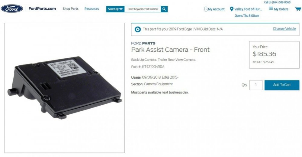
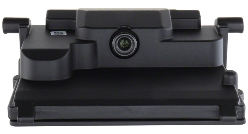
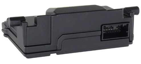
Document download links> IMAGE PROCESSING MODULE A (IPMA) - Connector C9224 Details - 2019 Edge.pdf IMAGE PROCESSING MODULE A (IPMA) - Connector C9224 Location - 2019 Edge.pdf IMAGE PROCESSING MODULE A (IPMA) - Wiring Diagram - 2019 Edge.pdf IMAGE PROCESSING MODULE A (IPMA) - Removal and Installation - 2019 Edge Workshop Manual.pdf IMAGE PROCESSING MODULE A (IPMA) - Removal and Installation - 2019 Edge Workshop Manual.pdf Lane Keeping System - System Operation and Component Description - 2019 Edge Workshop Manual.pdf Lane Keeping System - Component Location - 2019 Edge Workshop Manual.pdf Link to this FordParts webpage Good luck!
-
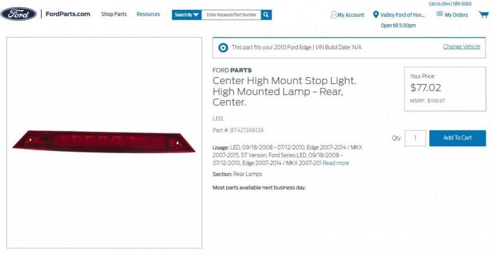
The 2007-2010 Edge wiring diagrams depict the lamps in the High Mounted Stop Lamp assembly as being conventional filament bulbs, while the 2011 Edge wiring diagram depicts LEDs. The currently offered Service replacement High Mounted Stop Lamp assembly is now LED for 2007-2014 Edge... Link to this FordParts web page Document download links> High Mounted Stop Lamp Wiring Diagram - 2007-2010 Edge.pdf High Mounted Stop Lamp Wiring Diagram - 2011-2014 Edge.pdf Wiring Diagram Symbols - Edge.pdf High Mounted Stop Lamp - Connector C904 Details - 2007-2014 Edge.pdf High Mounted Stop Lamp - Connector C904 Location - 2007-2014 Edge.pdf Good luck!
-
denny73: Nothing new specific to this topic, though there have been two unrelated UK Edition documents, consistent with Italy, recently released... Document download links> TSB 23-2379 - 2019-2022 Edge 2.0L EcoBlue - Illuminated AWD warning indicator or fault message with DTC C0095.pdf GSB 23-7123 - Various Models, Including Edge - Condensation inside the exterior lamp lens.pdf I think I'll try establishing an International Markets discussion thread to compile interested Forum members' Continent/Country SSM/GSB/TSB/Service-related releases. Based upon your inquiry, I'll start with EU/UK document editions and looking at Italy for commonality or uniqueness, but I'm willing to try expand to other Continent/Countries, based upon Forum member requests. If home-country language versions of documents are preferred. I may be able to accomplish that. Good luck!
-
From Ford's Service Awareness Newsletter for Dealership Service personnel... 12-Volt Battery Charging When charging the 12-volt battery on vehicles equipped with a battery monitoring sensor (BMS), the negative cable clamp of the battery charger must be connected to an engine or chassis ground as directed by the WSM (workshop manual) section 414-01> General Procedures> Battery Charging. Connecting the chargers’ negative cable clamp directly to the battery terminal will not allow the BMS to measure charging current flowing from the charger to the battery. Improper connection will result in the BMS SOC (state of charge) PID (parameter ID) failing to update to reflect the improved SOC. Never perform the BMS/SOC reset procedure unless the battery is replaced. The BMS should only be replaced if directed by the WSM. From Edge Workshop Manual... Battery Charging WARNING: Before beginning any service procedure in this section, refer to Safety Warnings in section 100-00 General Information. Failure to follow this instruction may result in serious personal injury. NOTE: Batteries will discharge due to normal parasitic key off-loads when the vehicle is on a dealer lot or parked by the customer for an extended period of time. Vehicles still in dealer inventory or in long-term storage may be driven short distances with heavy electrical loads. Over a period of time (30 days or more), this could result in vehicles having shallow or deeply discharged batteries. NOTE: The vehicle charging system is designed to supply the electrical power needed to maintain the battery near full charge during normal vehicle use. The charging system is not capable of bringing a deeply discharged battery back to near full charge in a short amount of time such as allowing the vehicle to idle for 15 minutes to recharge the battery. Use an external charger to charge discharged batteries. NOTE: Cold batteries will not readily accept a charge. Allow batteries to warm to approximately 5°C (41°F) before charging. This may require 4 to 8 hours at room temperature. Charger Connected to Engine or Chassis Ground - Preferred Method Connect the positive (red) charger clamp to the positive battery post. NOTICE: Do not connect the negative (black) charger clamp directly to the battery monitoring sensor, it must be connected to an engine or chassis ground to relearn the battery's state of charge. Connect the negative (black) charger clamp to the negative battery ground cable bolt or an engine ground. Charge the battery following the battery charger manufacturer's instructions.
-
From Ford's Service Awareness Newsletter for Dealership Service personnel... 2020-2024 Edge Wiper Motor Warranty Ford warranty has experienced several wiper motor replacement warranty claims that were the result of stripped wiper motor gears. It has been shown that wiper motor gears can strip as a result of customers improperly lifting up the wiper arms off of the windshield or manually pulling the wiper arms while the vehicle ignition is on. The Owner's Manual advises customers that the vehicle should be off before replacing the front wiper blades and has also recently been updated to caution customers to not manually move the wiper arms when the ignition is on or in accessory mode as this could damage the wiper motor. Stripped wiper motors will exhibit a grinding noise from the wiper motor with no wiper blade movement when turned on.
-
From Ford's Professional Technician System, this "What's New" advice to Dealership Service personnel... 2024 Nautilus Keypad Code Some 2024 Nautilus vehicles may incorrectly list the keypad code card on the loose item checklist. No keypad code cards were shipped or included in 2024 Nautilus vehicles for North America. To retrieve the vehicle’s keyless entry pad code, refer to the Keyless Entry Keypad Master Access Code section of the Owner’s Manual. This process will require the use of both programmed intelligent access keys. From the 2024 Nautilus Owner's Manual, pages 85-86... KEYLESS ENTRY KEYPAD MASTER ACCESS CODE What is the Master Access Code The master access code is a factory-set five-digit entry code. You can operate the keypad with the master access code at any time. The master access code can be displayed in the instrument cluster display and is available from an authorized dealer. Displaying the Master Access Code in the Instrument Cluster Display Read and understand the following before you begin the process. • You must have two previously programmed intelligent access key inside your vehicle. • Make sure that your vehicle is off. • Make sure you do not press the brake pedal during the procedure. • Make sure that you close all the doors and that they remain closed throughout the procedure. Perform all steps within 30 seconds of starting the sequence. If you perform any of the steps out of sequence, stop and wait for at least one minute before starting again. Note: Do not place the [Passive Key] device on the wireless accessory charging area during the procedure. 1. Access the backup slot. See Accessing the Passive Key Backup Position (page 190). 2. Place the first intelligent access key into the backup slot. 3. Press the push button ignition switch once and wait for a few seconds. 4. Press the push button ignition switch again and remove the intelligent access key from the center console. 5. Insert the second programmed intelligent access key into the backup slot in the center console, then press the push button ignition switch. The master access code appears in the instrument cluster display for a few seconds. Note: The code may not display until after other warning messages display From the 2024 Nautilus Owner's Manual, page 190... ACCESSING THE PASSIVE KEY BACKUP POSITION 1. Open the floor console storage compartment lid. 2. Place the passive key into the backup slot.
-
If your Edge is equipped with the Sony Audio System, the Sony Audio Digital Signal Processing (DSP) Module is mounted immediately behind the Loadspace Trim Panel that you have marked in your photo... Good luck!
Module-2016Edge.thumb.jpg.456e8085a1686aead642823c8dd54d3b.jpg)
-
Click on this link to download the full Removal and Installation procedure... Loadspace Trim Panel - Removal and Installation - 2016 Edge Workshop Manual.pdf Good luck!


Module-2016Edge.jpg.f6a984e8b11e39b7c1c20790e8bdcd24.jpg)