


Haz
-
Posts
1,251 -
Joined
-
Last visited
-
Days Won
325
Content Type
Profiles
Forums
Gallery
Everything posted by Haz
-
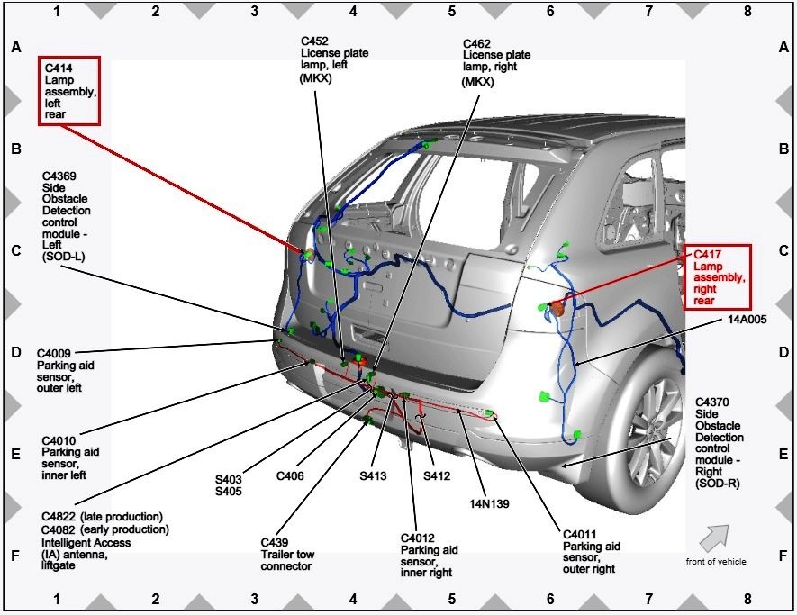
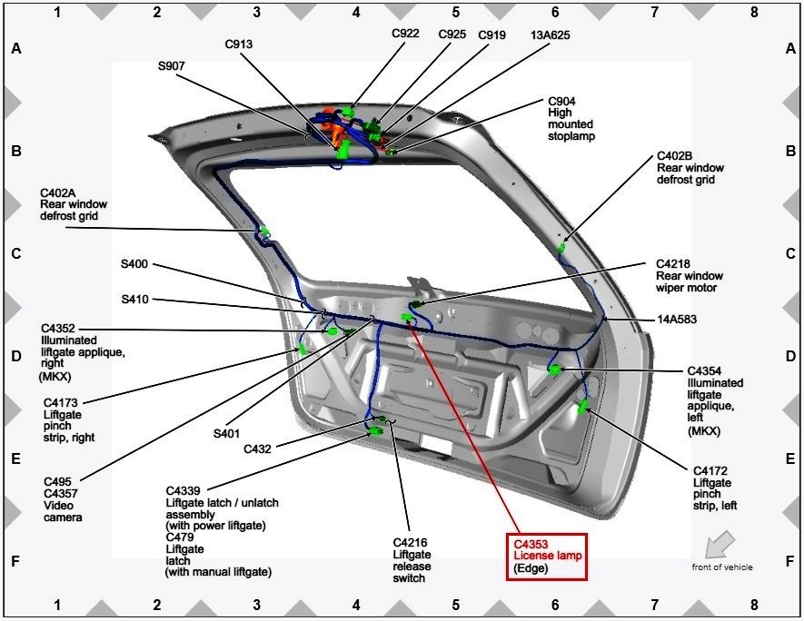
I presume you have disconnected all lamp assembly (left, right, license) connectors, replaced the blown fuse, then reconnected lamp connectors one-by-one, in an attempt to isolate and determine which lamp assembly is shorted? Document download links> Parking, Rear and License Lamps - Wiring Diagram 1 - 2013 Edge Workshop Manual.pdf Parking, Rear and License Lamps - Wiring Diagram 2 - 2013 Edge Workshop Manual.pdf Parking, Rear and License Lamps - Wiring Diagram 3 - 2013 Edge Workshop Manual.pdf LAMP ASSEMBLY, LEFT REAR - Connector C414 Details - 2013 Edge Workshop Manual.pdf LAMP ASSEMBLY, RIGHT REAR - Connector C417 Details - 2013 Edge Workshop Manual.pdf LICENSE LAMP, REAR - Connector C4353 Details - 2013 Edge Workshop Manual.pdf LAMP ASSEMBLY, LEFT & RIGHT REAR - Connectors C414 & C417 Locations - 2013 Edge Workshop Manual.pdf Rear Lamp Assembly - Removal and Installation - 2013 Edge Workshop Manual.pdf LICENSE LAMP, REAR - Connector C4353 Location - 2013 Edge Workshop Manual.pdf Liftgate Trim Panel - Removal and Installation - 2013 Edge Workshop Manual.pdf Liftgate Trim Panel - Removal and Installation - Enhanced Illustration - 2013 Edge Workshop Manual.pdf Good luck!
-
*** Customer Satisfaction Program 21B09 for 2016-2017 MKX has been extended to July 31, 2023 *** Owners interested in upgrading their MKX's Telematics Control Unit (TCU) from 3G to 4G capability, to preserve LincolnWay access, should contact their dealer. A new letter of notification will be sent to owners of 2016-2017 MKXs with built dates of August 31, 2015 through September 29, 2017 that have not received this TCU upgrade. New! PROGRAM TERMS This program will be in effect through July 31, 2023. There is no mileage limit for this program. NOTE: Owners may purchase the 4G upgrade kit and 21B09 covers labor/installation and one-time use components for 2016-2017 Lincoln MKX (and 2013-2016 Fusion Energi, 2015-2016 Lincoln MKZ). NOTE: Owners outside of the 21B09 program have the option to pay for both the labor and cost to purchase the 4G upgrade kit. Document download links> Customer Satisfaction Program 21B09, Supplement 2 - 3G TCU Upgrade to 4G - MKX Owner Letter - NEW.pdf Customer Satisfaction Program 21B09, Supplement 2 - 3G TCU Upgrade to 4G - MKX Service Procedure.pdf Good luck!
- 1 reply
-
- 1
-

-
Welcome to the Forum! Document download link> Blower Motor - Removal and Installation - 2018 Edge Workshop Manual.pdf Good luck!
-
Sync 2 to Sync 3 upgrade kit, $550 obo
Haz replied to enigma-2's topic in Audio, Backup, Navigation & SYNC
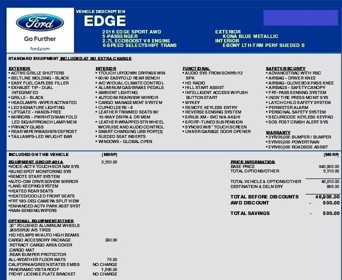
The following are APIM As-Built values from a 2016 Edge Sport SYNC 3 vehicle equipped comparably to your 2015 Edge Sport SYNC 2 vehicle... 7D0-01-01 AA2A 0503 00B5 7D0-01-02 028B 0006 8AF7 7D0-02-01 5553 0104 E46B 7D0-02-02 0340 8000 009E 7D0-02-03 0000 DC 7D0-03-01 0000 0002 00DD 7D0-04-01 0100 0300 00E0 7D0-04-02 0007 E4 7D0-05-01 1BA3 1B9B 2B7C 7D0-05-02 C5A3 7D0-06-01 805E 7D0-07-01 0800 3300 001A 7D0-07-02 0000 186A 0062 7D0-07-03 0056 5686 0013 7D0-07-04 7052 7D0-08-01 0000 0000 00E0 7D0-08-02 0000 0000 00E1 Window Sticker for your 2015 Edge Sport SYNC 2 vehicle... Window Sticker for the 2016 Edge Sport SYNC 3 vehicle from which the above APIM values were obtained... I've used the Forum Messaging system to provide you a download link to information that file size limitations prevent me from sharing here. There are many Forum members who have successfully accomplished the conversion your are embarking upon, and I will leave it to them to be your advisors if you encounter difficulties or require fine tuning suggestions. Good luck!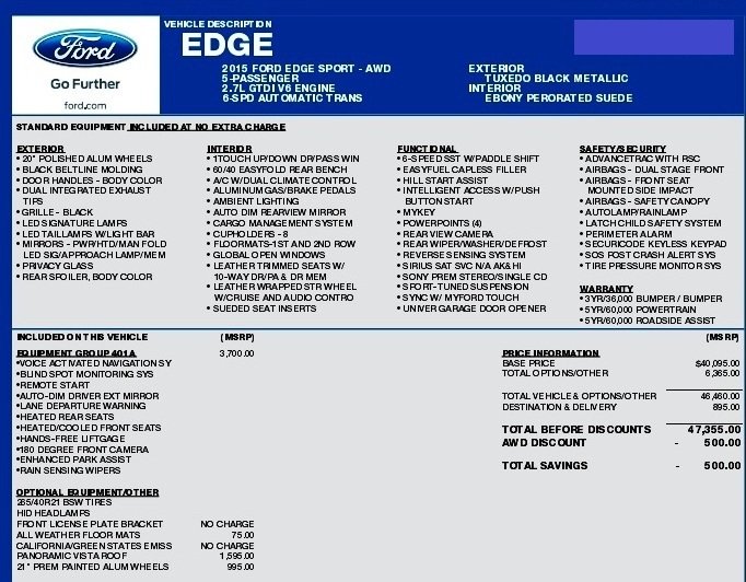
-
Noisy hinge cover on arm reast
Haz replied to johnmarkp's topic in Interior, A.C., Heat, Interior Trim
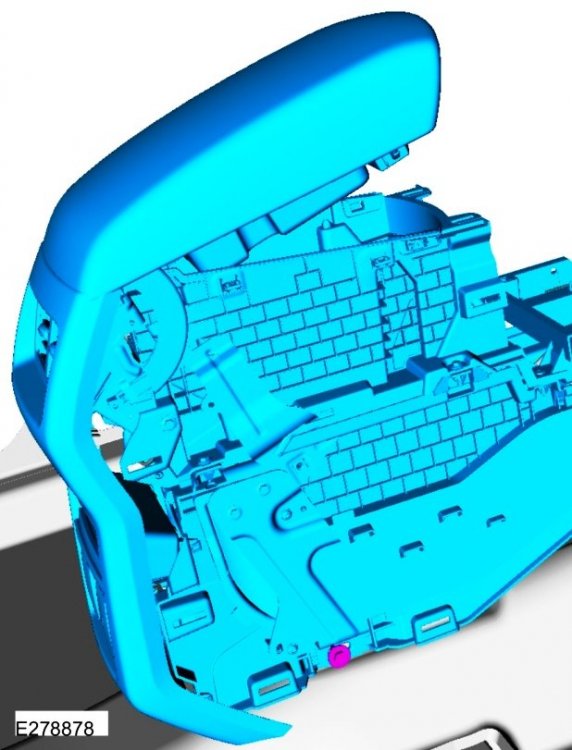
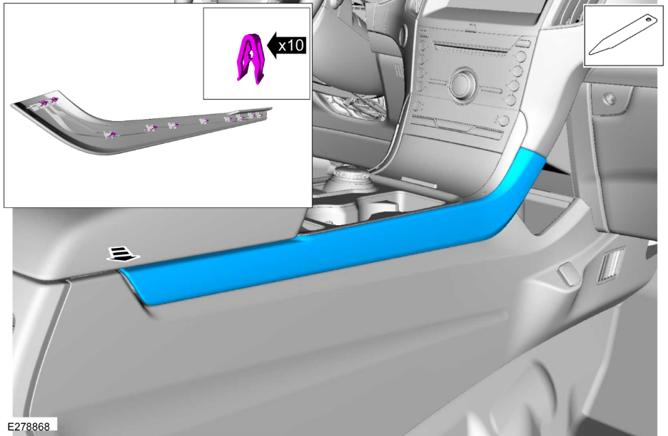
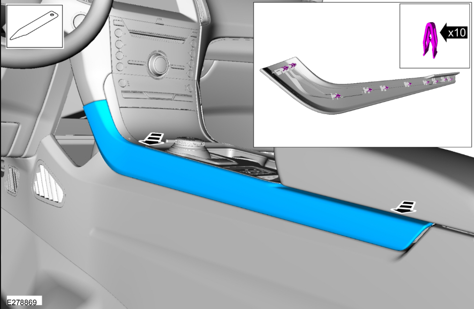
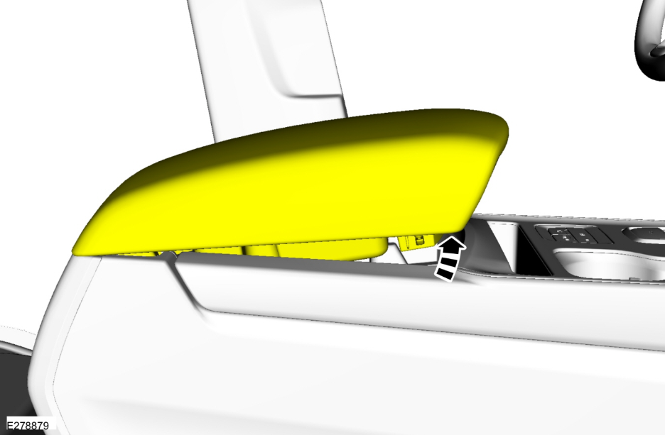
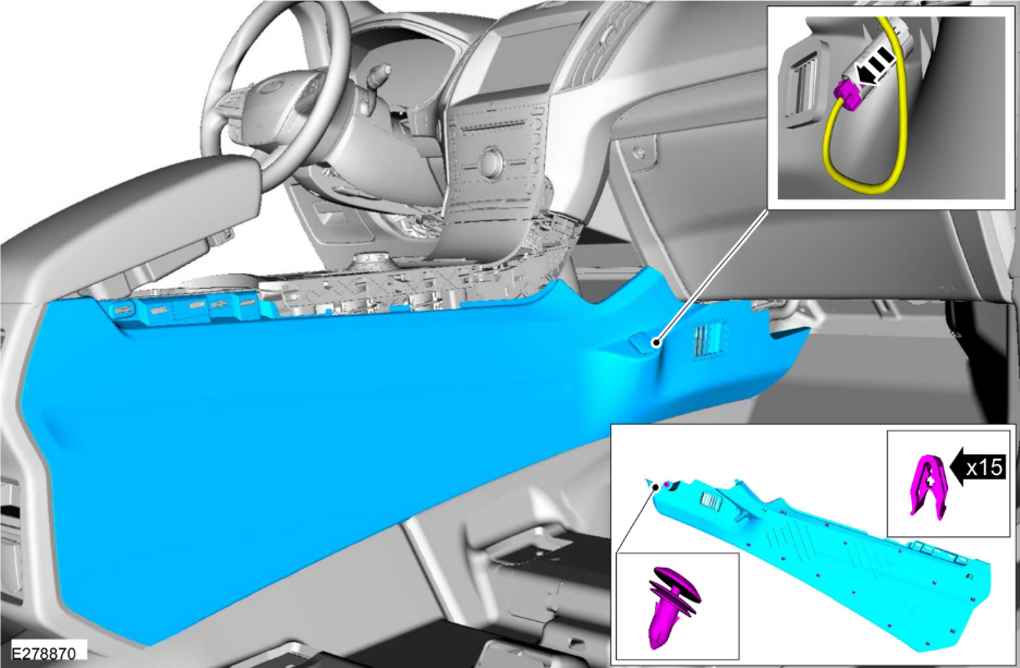
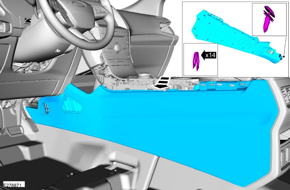
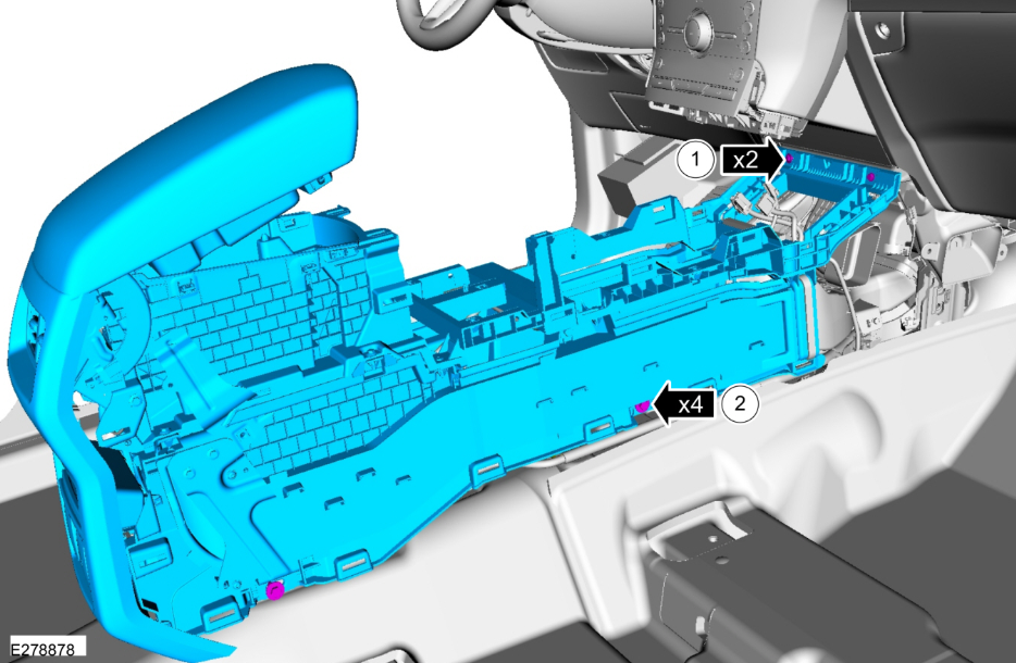
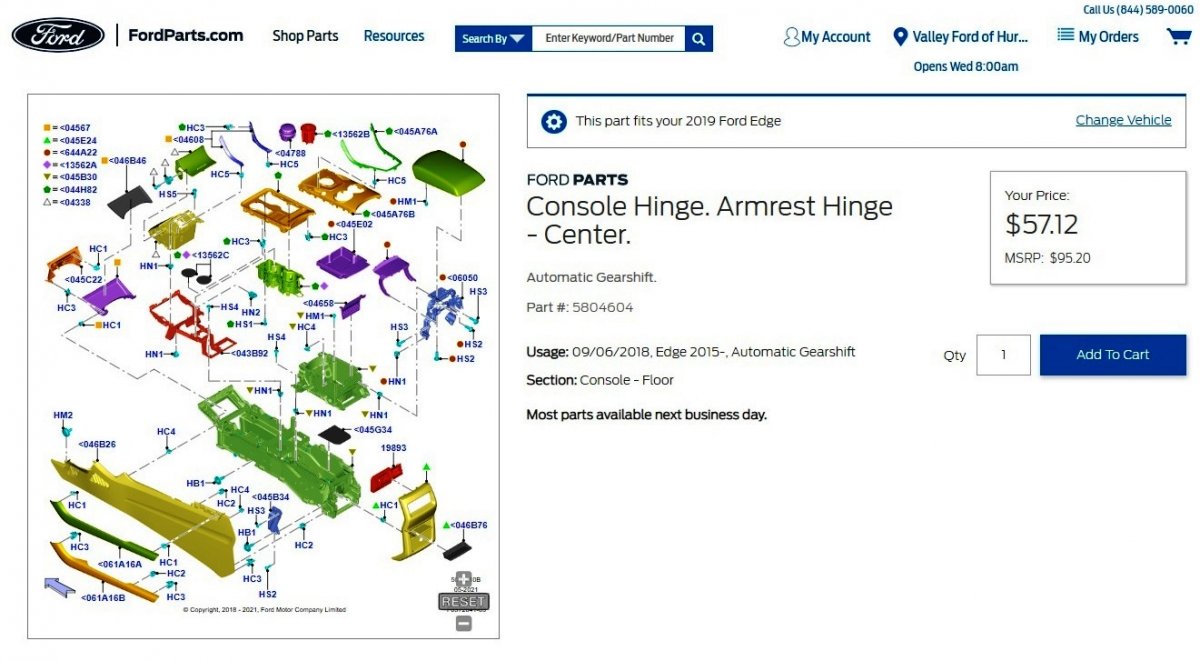
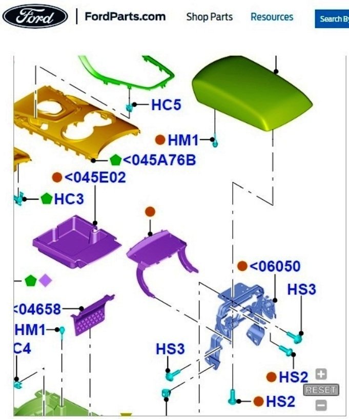
The 2019 Edge Workshop Manual and Ford's online parts website, FordParts.com, provide some insights. This illustration from the Workshop Manual indicates removing the Floor Console side trim panels exposes much of the hinge assembly and adjacent components that could be contributing to the creaking noise, and any possible surface vibration in components that you might be able to isolate, by feel, as you move the lid up & down... Workshop Manual direction on Side Trim Panel removal... Special Tool(s) / General Equipment Interior Trim Remover Removal NOTE: Removal steps in this procedure may contain installation details. All vehicles Release the clips and remove the RH floor console finish panel. Use the General Equipment: Interior Trim Remover Release the clips, push pin and remove the LH floor console side trim panel. Use the General Equipment: Interior Trim Remover Open floor console armrest. Release the clips, push pin and remove the RH floor console side trim panel. Disconnect the electrical connector. Release the clips, push pin and remove the LH floor console side trim panel. Resulting console appearance... Document download links> Floor Console - Right Hand, Upper Side Trim Panel Removal - Illustration - 2019 Edge Workshop Manual.pdf Floor Console - Left Hand, Upper Side Trim Panel Removal - Illustration - 2019 Edge Workshop Manual.pdf Floor Console - Right Hand, Side Trim Panel Removal - Illustration - 2019 Edge Workshop Manual.pdf Floor Console - Left Hand, Side Trim Panel Removal - Illustration - 2019 Edge Workshop Manual.pdf Floor Console with Side Trim Panels Removed - Illustration - 2019 Edge Workshop Manual.pdf The FordParts website provides an exploded view Floor Console parts illustration on this page (link)... ...which can be zoomed and dragged about in order to see fastener & component relationships to, hopefully, aid in your correction of the noise issue... Good luck!

-
A few PTU-related sections from the 2019 Edge Workshop Manual... Document download links> Power Transfer Unit Cooler - Vehicles With Power Transfer Unit Oil-to-Coolant Cooler - Removal and Installation - 2019 Edge Workshop Manual.pdf Power Transfer Unit Coolant Pump - Removal and Installation - 2019 Edge Workshop Manual.pdf Oil Temperature Sensor - Removal and Installation - 2019 Edge Workshop Manual.pdf Power Transfer Unit - Description and Operation - 2019 Edge Workshop Manual.pdf Power Transfer Unit Actuator Motor - Removal and Installation - 2019 Edge Workshop Manual.pdf Good luck!
-
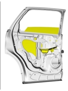
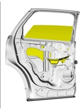
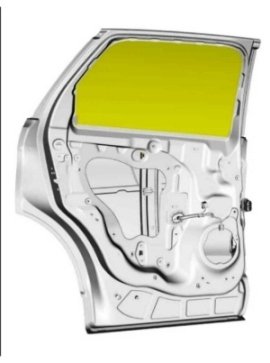
Back seat windows on 2019 Edge Titanium
Haz replied to Kennyk39's topic in Interior, A.C., Heat, Interior Trim
Online and 2019 Edge Workshop Manual images... Left Rear Door Glass profile Left Rear Door Glass movement Good luck!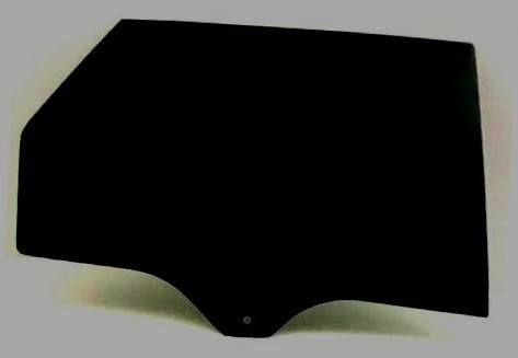
-
Door ajar switch info is offered in this recent post... Good luck!
-
Sync 2 to Sync 3 upgrade kit, $550 obo
Haz replied to enigma-2's topic in Audio, Backup, Navigation & SYNC
From the 2015 Edge Workshop Manual... Document download links> Global Positioning System Module (GPSM) - Removal & Installation - 2015 Edge Workshop Manual.pdf A-Pillar Trim Panel - Removal & Installation - 2015 Edge Workshop Manual.pdf Global Positioning System Module (GPSM) - Connector C2398 Location - 2015 Edge Workshop Manual.pdf Global Positioning System Module (GPSM) - Connector C2398 Details - 2015 Edge Workshop Manual.pdf Global Positioning System Module (GPSM) - Wiring Diagram - 2015 Edge Workshop Manual.pdf Good luck! -
From the 2019 Edge Workshop Manual... Power Transfer Unit (PTU) Description The Power Transfer Unit (PTU) is a gearbox that attaches to the transmission. The PTU directs power from the transmission differential case through a dog clutch to a hypoid ring gear. A hypoid pinion gear is meshed to the ring gear and splined to the output flange. A dog clutch is used to transfer drive torque from the input shaft to the ring gear. When the dog clutch is released, no torque is transferred through the ring gear and pinion to the rear driveshaft. When the dog clutch is engaged, normal AWD function is achieved by directing torque to the rear wheels as needed to prevent or control wheel slip and improve handling There are two different models of the PTU. The low torque PTU is paired with the 8F35, 8F40, and MMT6 transmissions. The high torque PTU is paired with the 8F57 transmission. The low torque and high torque PTUs are similar in design and operation. Power Transfer Unit (PTU) Operation The PTU has four (4) distinct modes of operation: Connected, Connecting, Disconnected, and Disconnecting. Each mode is commanded by the AWD module. The PTU contains a reversible DC motor and two hall effect position sensors. The motor moves the shift fork which connects or disconnects the dog clutch collar. PTU Position sensor A monitors the position of the actuator cam. PTU Position sensor B monitors the position of the shift fork. Some PTU models are equipped with an oil temperature sensor. Connected Mode Connected Mode is the default mode for the PTU. The AWD module will command Connected mode at the beginning of each key cycle. In connected mode, the fork and dog clutch collar are positioned towards the RH side of the PTU. The dog clutch is engaged. The driveshaft is rotating at an overdrive ratio compared to the front axle shafts. Torque is available at the RDU. Connecting Mode To connect the PTU, the two halves of the Dog clutch must be within 40 RPM of each other. The AWD module calculates the speed differential based on transmission OSS, RDU Driveshaft Speed, and PTU gear ratio. The actuator motor will energize and rotate the gear reduction drive and the actuator cam against the actuator fork. When the dog clutch teeth line up, the cam pushes the actuator fork into position and the clutch engages. It can take approximately 100 - 150ms for the dog clutch to engage after the command is sent. Disconnected Mode The AWD module will command disconnected mode based on vehicle conditions. The purpose of the disconnected mode is to reduce drag losses from spinning the driveshaft when conditions indicate AWD will probably not be needed in the near future. In disconnected mode, the fork and dog clutch collar are positioned towards the LH or transmission side of the PTU. The dog clutch is disengaged. Disconnecting Mode To disengage the PTU, no torque can be routed through the dog clutch. That is, the RDU must be completely disengaged. Depending on vehicle conditions, the AWD module may keep the PTU engaged for the remainder of the key cycle. The actuator motor will energize and rotate the gear reduction drive and pull the actuator cam away from the actuator fork. When the dog clutch collar has moved far enough to the LH or transmission side, the dog clutch teeth disengage. Good luck!
-
2020 SE aftermarket fog lights
Haz replied to Edge_Eco20's topic in Glass, Lenses, Lighting, Mirrors, Sunroof (BAMR), Wipers
If you'd like to research used parts as an alternative to new, the Car-Part.com salvage yard search engine might yield a source in your area. Most listings provide photos of the donor vehicle & offered part, its condition grading & pricing, as well as contact information for the selling salvage yard. In my area, pricing varied widely, from $45 to $85 to $235 per left or right assembly -- so make sure you know exactly what you'd be getting for your money. Good luck!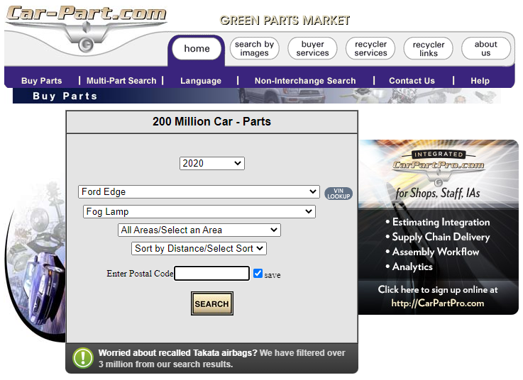
-
SSM 51536 2000-2024 Various Vehicles - Errors Caused By Swapping Modules From Like Vehicles Or Ordering Modules Using Another VIN For 2000-2024 Ford and Lincoln vehicles, swapping a module from a vehicle for diagnosis purposes is likely to cause errors and is not recommended. It is also not recommended to order a replacement module using a vehicle identification number (VIN) from a different vehicle. Most modules on these affected vehicles are VIN/vehicle specific and hardware variations between modules do exist. Swapping a module from a vehicle or ordering a module using a different vehicle/VIN can cause ineffective repairs and additional vehicle down time. Make sure all appropriate Workshop Manual (WSM) procedures are followed when diagnosing the condition prior to all module replacements and only order modules using the correct VIN.
-
Need power source for radar detector
Haz replied to Wildcats79's topic in Accessories & Modifications
Because your Lane Departure System camera part number resolves to 2019+ Edge, Forum member Vanquished's recent discussion may be helpful... New 2019+ Ford Edge Dashcam Adapter (Plug and Play) Good luck! -
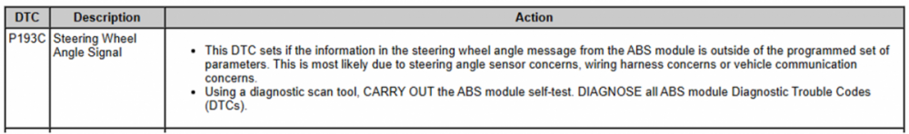
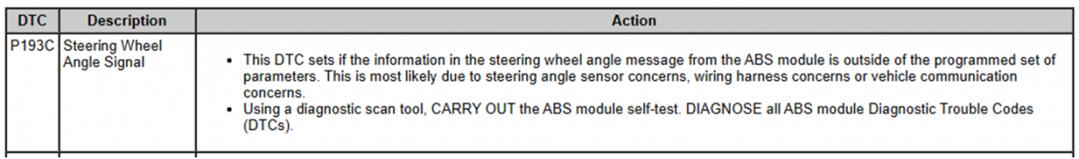
Front and rear alignment procedures in the 2014 Edge Workshop make no mention of need to recalibrate any modules or sensors, and the Steering Sensor's description indicates its function measures direction and angle of Steering Wheel rotation only (with emphasis added). Steering Sensor The steering wheel rotation sensor uses an optical sensor and a slotted wheel to measure the rate of rotation (angle) of the steering wheel. The steering wheel rotation sensor uses the HS-CAN to transmit information to the ABS module about steering wheel turning direction (left or right) and how far the steering wheel is being turned. The steering wheel rotation sensor does not indicate the absolute position of the steering wheel relative to straight-ahead. The ABS module learns this position by comparing the steering wheel position with other signals and storing the position it has learned. The module confirms this position and modifies it as necessary during every new driving cycle. Document download links> Steering Wheel Rotation Sensor - Removal and Installation - 2014 Edge Workshop Manual.pdf Steering Column Control Module (SCCM) - Removal and Installation - 2014 Edge Workshop Manual.pdf Anti-Lock Control - Diagnosis and Testing - 2014 Edge Workshop Manual.pdf Will2U, you're probably rightfully recalling that following front or rear Toe Adjustment, beginning with 2015 Edges, GEN 2 vehicles equipped with the Lane Departure Warning (LDW) System require the camera alignment procedure to be performed on the vehicle's Image Processing Module A (IPMA) using a scan tool. Good luck!
-
2011 Ford Edge Door Sensor Button inside the latch - Where is it?
Haz replied to CMOS's topic in Exterior & Body
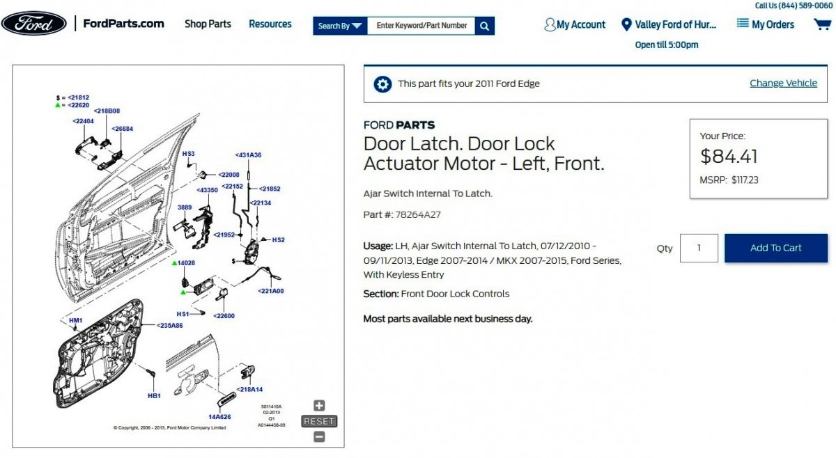
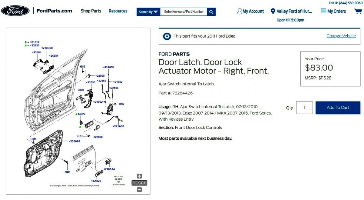
For future reference: Ford's parts website provides hi-res/large format images of the right and left front latch assemblies which might enable drawing conclusions on door ajar switch location... Links to Left Front Latch images - Photo #1, Photo #2, Photo #3, Photo #4; Link to the following FordParts webpage Links to Right Front Latch images - Photo #1, Photo #2, Photo #3, Photo #4; Link to the following FordParts webpage Document download links> TSB 18-2013 - 2011-2013 Edge-MKX + Other Models - Door Ajar Lamp Remains Illuminated With Doors Closed.pdf Front Door Latch - Removal and Installation - 2011 Edge Workshop Manual.pdf Front Door Latch - Removal and Installation - Enhanced Pg 1 Illustration - 2011 Edge Workshop Manual.pdf Front Door Latch - Removal and Installation - Enhanced Pg 2 Illustration - 2011 Edge Workshop Manual.pdf Rear Door Latch - Removal and Installation - 2011 Edge Workshop Manual.pdf Good luck!

-
Roof Cabin's website shows two models that look comparable to your photos. Can you please advise whether your Roof Cabin is the Streamline or Streamline Plus? Good luck!
-
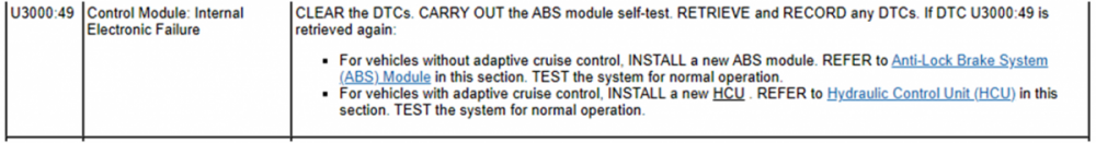
From the 2014 Edge Workshop Manual... Document download links Anti-Lock Brake System (ABS) Module - Removal and Installation - 2014 Edge Workshop Manual.pdf Hydraulic Control Unit (HCU) - Removal and Installation - 2014 Edge Workshop Manual.pdf Hydraulic Control Unit (HCU) - Removal and Installation - Enhanced Page 2 Illustration - 2014 Edge Workshop Manual.pdf Module Configuration (Less Non-Applicable DTC Chart) - 2014 Edge Workshop Manual.pdf Programmable Module Installation (PMI) - General Procedures - 2014 Edge Workshop Manual.pdf Good luck!

-
Document download link> TSB 23-2049 - 2019-2023 Edge-Nautilus - 2.7L EcoBoost - Cold Start Ticking-Tapping Or Rattle Type Noise.pdf TECHNICAL SERVICE BULLETIN 2.7L EcoBoost - Cold Start Ticking/Tapping Or Rattle Type Noise 23-2049 28 March 2023 This bulletin supersedes 22-2376. Model: Ford 2019-2023 Edge Engine: 2.7L EcoBoost Lincoln 2019-2023 Nautilus Engine: 2.7L EcoBoost Summary This TSB supersedes TSB 22-2376 to update the model years affected. Issue: Some 2019-2023 Edge/Nautilus vehicles equipped with a 2.7L EcoBoost engine may exhibit a ticking/tapping or rattle type noise from the top front cover area of the engine on initial start-up after a cold soak of 6 hours or more that may last for 2-5 seconds. This may be due to stuck internal components of the variable cam timing (VCT) unit. To correct the condition, follow the Service Procedure to replace the VCT units. Action: Follow the Service Procedure to correct the condition on vehicles that meet all of the following criteria: • 2019-2023 Edge/Nautilus • 2.7L EcoBoost engine • Customer symptom of ticking/tapping or rattle noise from the front cover area after a cold start NOTE: Dealers should only order parts for customer vehicles that require repairs. Because of part constraints, dealers may experience situational short-term backorders on some parts. Customers should continue to drive vehicles while parts are on order. Parts All Vehicles - Required Parts Service Part Number Quantity Description Unit of Issue Piece Quantity CP9Z-6279-C 4 VCT Unit Bolts 1 4 FT4Z-6A340-A 1 Crankshaft Pulley Bolt 1 1 KU2Z-6731-A 1 Engine Oil Filter 1 1 JT4Z-6710-A 1 Oil Pan Press-In-Place Gasket 1 1 KT4Z-6710-A 1 Oil Pan Gasket 1 1 FT4Z-6626-A 1 Oil Pump Seal 1 1 FT4Z-6020-G 1 Coolant Pump Gasket 1 1 FT4Z-8507-C 1 Coolant Pump Seal 1 1 XW4Z-6700-B 1 Crankshaft Front Oil Seal 1 1 FT4Z-6020-K 1 Engine Front Cover Gasket 1 1 1 FT4Z-6020-H 1 Engine Front Cover Gasket 2 1 1 FT4Z-6020-J 1 Engine Front Cover Gasket 3 1 1 FT4Z-6020-A 1 Engine Front Cover Gasket 4 1 1 FT4Z-00815-C 1 Oil Gallery Seal 1 1 L1MZ-6256-C 2 VCT Unit - Intake 1 2 L1MZ-6C525-C 2 VCT Unit - Exhaust 1 2 BL3Z-9450-A 2 Catalytic Converter Gasket 1 2 FT4Z-6584-D 1 Left Valve Cover Gasket 1 1 FT4Z-6584-B 1 Right Valve Cover Gasket 1 1 FT4Z-6584-C 1 Left Valve Cover Gasket 1 1 FT4Z-6584-E 1 Right Valve Cover Gasket 1 1 1X4Z-9E936-AA 1 Throttle Body Gasket 1 1 DL3Z-19B596-B 1 A/C O-Ring Kit 1 1 DS7Z-19B596-A 1 A/C Gasket Kit 1 1 W712334-S440 2 Engine Mount Bracket-To-Engine Nuts 3 4 W717674-S439 1 Engine Mount-To-Frame Bolts 4 2 W710807-S442 1 Engine Mount-To-Frame Nut 4 1 W716457-S439 1 Subframe Bolts 4 2 W712458-S900 1 Exhaust Studs 4 4 W714265-S442 1 Catalytic Converter To Turbo Flange Nuts 4 4 VC-13DL-G As Needed Motorcraft® Yellow Prediluted Antifreeze/Coolant (All Markets Except Canada) CVC-13DL-G As Needed Motorcraft® Yellow Prediluted Antifreeze/Coolant (Canada Only) XO-5W30-Q1SP As Needed Motorcraft® SAE 5W-30 Synthetic Blend Motor Oil (All Markets Except Canada) CXO-5W30-LSP6 As Needed Motorcraft® SAE 5W-30 Super Premium Motor Oil (Canada Only) XL-2 As Needed Motorcraft® High Temperature Nickel Anti-Seize Lubricant ZC-37-A As Needed Motorcraft® Wheel and Tire Cleaner XL-1 As Needed Motorcraft® Penetrating and Lock Lubricant TA-26 As Needed Motorcraft® Threadlock 262 YN-35 As Needed Motorcraft® R-1234yf Refrigerant PAG Oil TA-357 As Needed Motorcraft® High Performance Engine RTV Silicone Parts Nautilus Only Parts Service Part Number Quantity Description Unit of Issue Piece Quantity W712961-S450B 1 Steering Shaft Coupler Bolt 4 1 W520215-S440 1 Tie Rod Nut 4 2 W712503-S440 2 Stabilizer Bar Nuts 1 2 W520214-S440 1 Ball Joint Nut 2 2 W500545-S439 1 Ball Joint Stud 4 2 W717016-S439 1 Rearward Subframe Bolt 4 2 Parts All Vehicles - Parts To Inspect And Replace Only If Necessary Service Part Number Quantity Description Unit of Issue FT4Z-6A832-C If Needed Oil Filter Housing And Stem 1 BR3Z-6C535-B If Needed Spark Plug Seals 1 Quantity refers to the amount of the service part number required to repair the vehicle. Unit of Issue refers to the number of individual pieces included in a service part number package. Piece Quantity refers to the total number of individual pieces required to repair the vehicle. As Needed indicates the amount of the part may vary and/or is not a whole number. Parts can be billed out as non-whole numbers, including less than 1. If Needed indicates the part is not mandatory. Warranty Status: Eligible under provisions of New Vehicle Limited Warranty (NVLW)/Emissions Warranty/Service Part Warranty (SPW)/Special Service Part (SSP)/Extended Service Plan (ESP) coverage. Limits/policies/prior approvals are not altered by a TSB. NVLW/Emissions Warranty/SPW/SSP/ESP coverage limits are determined by the identified causal part and verified using the OASIS part coverage tool. Labor Times Description Operation No. Time 2019-2023 Edge AWD 2.7L EcoBoost, Nautilus FWD/AWD 2.7L EcoBoost: Replace All 4 VCT Units (Do Not Use With Any Other Labor Operations) 232049A 14.7 Hrs. Repair/Claim Coding Causal Part: 6C525 Condition Code: 42 Service Procedure 1. Replace all 4 VCT units. Refer to Workshop Manual (WSM), Section 303-01. Do not replace any additional VCT or engine timing-related components not included in the Parts List. (1). All the VCT solenoid and spark plug tube seals require inspection, but not all require replacement. © 2023 Ford Motor Company All rights reserved. NOTE: The information in Technical Service Bulletins is intended for use by trained, professional technicians with the knowledge, tools, and equipment to do the job properly and safely. It informs these technicians of conditions that may occur on some vehicles, or provides information that could assist in proper vehicle service. The procedures should not be performed by "do-it-yourselfers". Do not assume that a condition described affects your car or truck. Contact a Ford or Lincoln dealership to determine whether the Bulletin applies to your vehicle. Warranty Policy and Extended Service Plan documentation determine Warranty and/or Extended Service Plan coverage unless stated otherwise in the TSB article. The information in this Technical Service Bulletin (TSB) was current at the time of printing. Ford Motor Company reserves the right to supersede this information with updates. The most recent information is available through Ford Motor Company's on-line technical resources.
-
2023 Edge Heat seats and steering wheel
Haz replied to Tom C's topic in Interior, A.C., Heat, Interior Trim
Welcome to the Forum! It's not clear from your post if you are describing the Heated Steering Wheel and Heated Seats in a default ON condition only when using Remote Start, or, if they are immediately ON after starting your Edge using the Push Button Start on your Edge's dash. If your new Edge was delivered with only the HTML Owner's Manual that's viewable on the Touchscreen panel, you can obtain a PDF version by clicking the following link... 2023 Ford Edge Owner's Manual, Version 1 (Direct download). From the HTML Owner's Manual, vehicle settings which affect the behavior of Climate Control system, Heated Seats, Heated Steering Wheel, and Duration of Remote Start when using the Intelligent Access (IA) key fob or FordPass to remotely start the vehicle... Remote Start (If Equipped) - Remote Start Settings REMOTE START SETTINGS Switching Climate Control Auto Mode On and Off Using the instrument cluster display controls on the steering wheel, select Settings. Select Vehicle. Select Remote Start. Select Climate Control. Select Auto or Last settings. Note: If you switch the auto mode on, the system attempts to heat or cool the interior to 72°F (22°C). When you switch the vehicle on, the climate control system returns to the last used settings. Note: If you switch the last settings on, the system remembers the last used settings. Heated Seat Settings Using the instrument cluster display controls on the steering wheel, select Settings. Select Vehicle. Select Remote Start. Select Seats. Select Auto or Off. Note: If you switch the heated seat settings on, the heated seats turn on during cold weather. Note: You cannot adjust the heated seat settings when you remotely start your vehicle. Heated Steering Wheel Settings Using the instrument cluster display controls on the steering wheel, select Settings. Select Vehicle. Select Remote Start. Select Seats and Wheel. Select Auto or Off. Note: If you switch the heated steering wheel settings on, the heated steering wheel turns on during cold weather. Note: You cannot adjust the heated steering wheel settings when you remotely start your vehicle. Remote Start Duration Using the instrument cluster display controls on the steering wheel, select Settings. Select Vehicle. Select Remote Start. Select Duration. Press the duration you prefer. 2023 Edge Owner's Manual The 2023 Edge Workshop Manual offers the following on the operation of Heated Seats and the Heated Steering, including their normal operating temperatures and the affect External Ambient Temperature has upon their operation after Remote Starting the vehicle. Placing your device cursor over acronyms underlined with dots will yield popup full-word descriptions of the acronym... System Operation and Component Description HVAC Module Network Input Messages Broadcast Message Originating Module Message Purpose Heated seat request APIM The heated seat request message allows the HVAC module to activate the heated seat(s) selected. APIM Network Input Messages Broadcast Message Originating Module Message Purpose Heated seat request HVAC Module The HVAC module provides this message to the APIM for the purpose of updating the displayed status of the heated seat buttons on the touchscreen. System Diagram - Climate Controlled Seats Network Message Chart - Climate Controlled Seats SCME Network Input Messages Broadcast Message Originating Module Message Purpose Climate control requests APIM The climate control requests message contains the climate controlled seat request information. Heated Seat Operation The driver and passenger heated seat buttons are selected from the touchscreen. The heated seat system functions independently of the vehicle's climate control system. Each time the heated seat button is pressed, the system decreases one setting (the sequence is high, med, low, off, high, etc.). When activated, the HVAC module supplies voltage to the selected seat heater circuit. Each seat cushion heater mat and backrest heater mat is connected in a series circuit to the HVAC module and powered by the output circuit for that seat. The HVAC module monitors inputs from a temperature sensor located in each seat cushion heater mat, and maintains seat temperature by cycling the heater circuits on/off. The heated seat remains ON until the heated seat switch button is pressed to cycle the system OFF or the ignition is set to OFF. If a fault is detected by the HVAC module, the module stops supplying voltage to that individual left or right seat that the fault was detected on until the ignition is turned OFF and then ON. Climate Controlled Seat Operation The driver and passenger climate controlled seat buttons are selected from the touchscreen. The climate controlled seat system functions independently from the vehicle's climate control system. The seat cushion and backrest are each equipped with a blower motor assembly. As cabin air is drawn through each blower motor, a Thermo-Electric Device (TED) heats or cools the air, which is then directed into the foam pad where it is distributed along the surface of the cushion and backrest of the seat. Once the system is activated, the SCME uses a set of flexible algorithms to control the heating/cooling modes and the blower speed dependant on the commanded climate controlled seat settings. The SCME monitors seat cushion temperature while it supplies voltage and ground to both blower motors. The SCME also supplies a variable voltage signal to control the blower speed. Cabin air enters the blower through an integrated filter attached to the blower motor housing. Heated or cooled air exits the blower motor and flows through the foam pad. Climate Controlled Seat Heating Characteristics The system control settings are indicated next to each climate controlled seat heat switch button. The first setting is HIGH (3 indicators), the second setting is MED (2 indicators) and the third is LOW (1 indicator) then OFF (no indicators). When heating, the SCME varies the speed of the blower motors and the duty cycle of the integral Thermo-Electric Device (TED) in order to reach and maintain the desired temperature determined by the system control settings. Climate Controlled Seat Cooling Characteristics The system control settings are based on the 3 indicators next to each climate controlled seat cool switch button. The first setting is HIGH (3 indicators), the second setting is MED (2 indicators) and the third is LOW (1 indicator) then OFF (no indicators). When cooling, the SCME maintains a constant blower motor speed and a constant Thermo-Electric Device (TED) supply voltage (duty cycle is determined by the switch setting) in COOL mode. Climate Controlled Seat Recovery Mode NOTE: The presence of overtemperature faults (Diagnostic Trouble Codes (DTCs) B1153:4B, B1154:4B, B1151:4B and B1152:4B) can be induced by incorrectly operating the climate controlled seat system after an initial heat setting has been attained. If a heat setting is repeatedly turned off and on in an attempt to increase the seat temperature or repeatedly toggled between heat and cool modes, an overtemperature condition can result and the Diagnostic Trouble Codes (DTCs) may be set. If the temperature of one of the blower motors rises above 110° C (229.8° F) in the heat mode or 65° C (149° F) in the cool mode for more than 4 seconds, the SCME records an overtemperature DTC , removes voltage from the Thermo-Electric Devices (TEDs) (part of the blower motor assembly) and goes into recovery mode (blower only) for 30 seconds to cool down the blower motor. The same occurs if a temperature difference of 60° C (140° F) or greater is detected between the backrest and cushion blower motors on either front seat. The SCME continues to monitor the blower motors while in recovery mode. If the temperature of the Thermo-Electric Devices (TEDs) do not drop to 105° C (220.8° F) in the heat mode or 60° C (140° F) in the cool mode after 30 seconds, the system continues to cool the blower motors in recovery mode for up to 5 minutes. If the Thermo-Electric Devices (TEDs) cool down after 30 seconds, but before 5 minutes (checked at 4 second intervals), the system is operating normally. An overtemperature DTC is still recorded even if the system recovers and is operating normally. This is more likely to occur during extreme cabin temperatures with significant seat back sun load. If the system does not recover within 30 seconds in heat mode or within 5 minutes in cool mode, the SCME disables that seat (fault mode) and remains off until the ignition is cycled. Also, if the SCME detects a temperature differential fault twice during the same ignition cycle, the SCME disables the seat. When a fault causes a shutdown, the climate controlled seat indicators turn off and that seat is not operational until the next ignition cycle. Remote Start Climate Operation Different climate control modes/preferences can be selected when the vehicle is started using the remote start feature. This can be accessed through the message center. For additional information on how to set the remote start preferences, refer to the Owner's Literature. When the driver seat and/or passenger seat is set to AUTO mode, the driver/passenger heated/climate controlled seat activates in full heat mode when the outside temperature is less than 0° C (32° F) and full cool mode (climate controlled seats only) when outside temperature is greater than 27° C (80° F) any time the vehicle is started using the remote start feature. No heated/climate controlled seat adjustments are recognized during remote start operation. Once the ignition is cycled ON, the heated/climate controlled seat turns off. System Diagram - Heated Steering Wheel Network Message Chart - Heated Steering Wheel HSWM Network Input Messages Broadcast Message Originating Module Message Purpose Engine power status PCM This message indicates to the HSWM whether the engine is running. Ignition status BCM Indicates which ignition mode is active. Steering wheel heat request FCIM Message is used to activate the heated steering wheel function when the touchscreen button is pressed on the FDIM , or when the conditions are met to activate the heated steering wheel (and heated seats) during a remote start. FCIM Module Network Input Messages Broadcast Message Originating Module Message Purpose Heated steering wheel command status APIM This message informs the FCIM that the heated steering wheel touchscreen button was pressed on the FDIM . Ambient exterior temperature data IPC This message is used by the FCIM when determining if outside conditions are cold enough to request the heated steering wheel be activated during remote start operation. Heated Steering Wheel When the engine is running and the HSWM receives a request to heat the steering wheel, the HSWM applies voltage and ground to the steering wheel heating elements (integral to the steering wheel) to heat the steering wheel to a temperature of approximately 28-34°C (82-94°F). The heated steering wheel temperature is maintained by the HSWM using a temperature sensor in the steering wheel. The HSWM is designed to remain on, heating the steering wheel and maintaining the temperature until switched off on the FDIM or the ignition is turned off. The controls and indicators for the heated steering wheel system are located on the FDIM (touchscreen) only. The FDIM does not communicate on any network and is connected directly to the APIM . Remote Start System The heated steering wheel system (along with the heated front seats) may be configured using the message center to activate when the remote start feature is used, based on outside air temperature. During remote start, the outside air temperature is continually monitored by the HVAC system. The heated steering wheel system activation changes if the outside air changes from cold to moderate or warm temperatures or back from moderate or warm to cold temperatures. Good luck!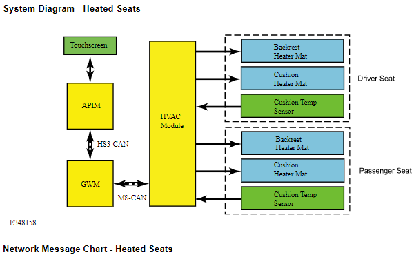
-
Welcome to the Forum! We Ford/Lincoln owners -- and you might also say, Floridians -- are a loyal and sometimes long-suffering bunch. Replacement tire choices can compound the road noise. Good luck!
-
Once again, there is no flasher relay for you to change. The Smart Junction Box (SJB) contains built-in components which control the voltage flow to cycle turn signal lamps on-and-off, as described in the Workshop Manual description. While I have no first-hand experience with it, because my MKXs were equipped with LEDs from the factory, the linked discussions suggest you are looking at adding resistors to eliminate the quick-flash, or, purchase LED arrays that already have the resistor built-in. Good luck!
-
The flasher relay is hard to find because it's function is integral & internal to your Edge's Smart Junction Box (SJB)... This description is from the 2010 Edge Workshop Manual... Turn Signal/Hazard Lamps The front turn signal lamps are located within the headlamp assemblies. The rear lamps share functionality with the stoplamps. When the multifunction switch is placed in the LH or RH TURN positions, the SJB routes voltage to the LH or RH turn signal lamps. The SJB then cycles the voltage on and off approximately 80 times per minute. If a front or rear turn bulb is inoperative, the SJB cycles the voltage on and off approximately 160 times per minute. The hazard switch is located on the center instrument panel finish panel. When the hazard switch is pressed, the SJB supplies voltage to all the turn lamps. The SJB cycles the voltage on and off approximately 80 times per minute. These two discussions should be helpful... Taillight LED Turn Signal Hyperflash LED bulbs - rear turn signals Good luck!
Illustration-2010EdgeWorkshopManual.jpg.17d302bad3a4ddcc0316a2720ca48904.jpg)
-
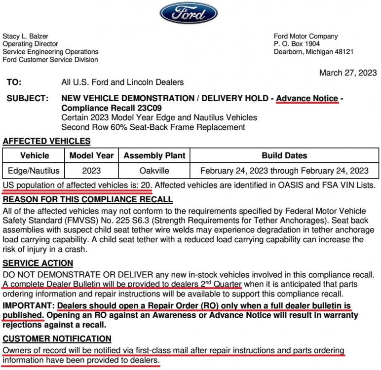
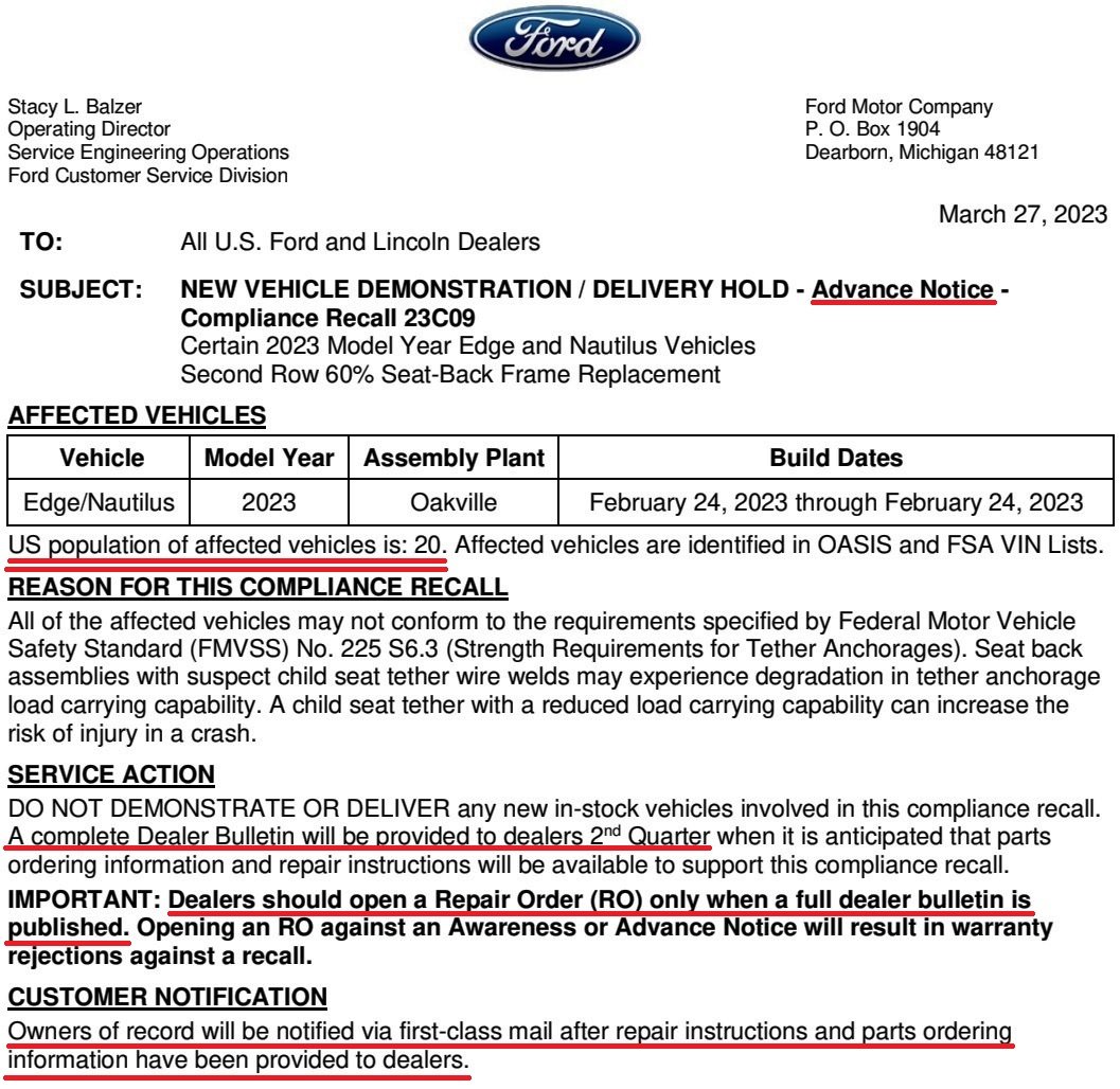
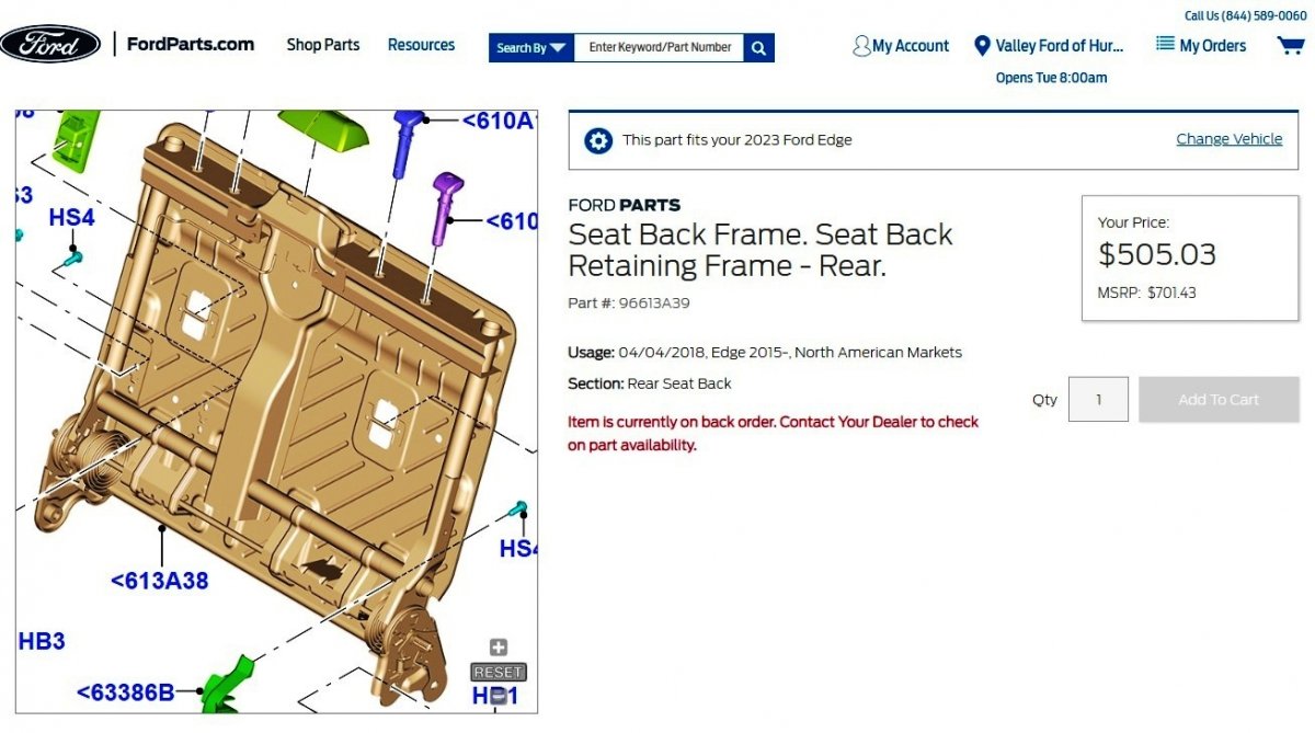
***Advance Notice To Dealers*** Dealers are effectively unable to perform seat frame replacement until complete Dealer Notice with parts-ordering information is released in 2nd Quarter 2023, when notification letters to affected vehicle Owners will also be mailed. Seat-Back Frame example from Ford's online parts site, not provided in above Dealer notification

- 1 reply
-
- 3
-
-
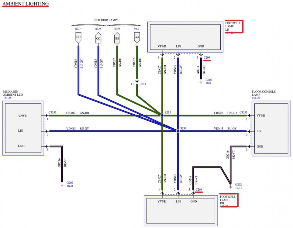
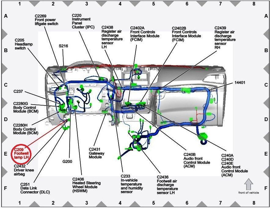
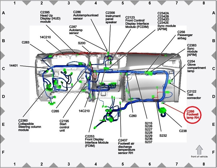
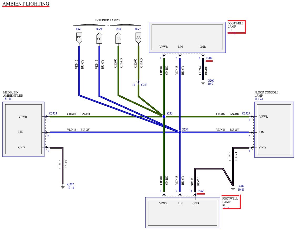
From the 2018 Edge Workshop Manual... One Or More Of The Ambient Lighting LEDs Are Inoperative Or Do Not Change Color/Intensity Refer to Wiring Diagrams for schematic and connector information. **Download links to Connector details documents is at bottom of this post** Normal Operation and Fault Conditions REFER to: Interior Lighting - System Operation and Component Description **Download link to this document at bottom of this post** DTC Fault Trigger Conditions DTC Description Fault Trigger Conditions B1465:00 Ambient Lighting Bus 1: No Sub Type Information Sets when the BCM detects a fault in the LIN circuit to the door ambient lighting Light Emitting Diodes (LEDs). B1467:00 Ambient Lighting Bus 3: No Sub Type Information Sets when the BCM detects a fault in the LIN circuit to the footwell and center console ambient lighting Light Emitting Diodes (LEDs). Possible Sources Wiring, terminals or connectors Ambient lighting LED BCM PINPOINT TEST I: ONE OR MORE OF THE AMBIENT LIGHTING LIGHT EMITTING DIODES (LEDS) ARE INOPERATIVE OR DO NOT CHANGE COLOR/INTENSITY I1 CHECK THE AMBIENT LIGHTING LIGHT EMITTING DIODES (LEDS) Ignition ON. Place the headlamp switch in the PARKING LAMPS position. Observe the operation of all the ambient lighting Light Emitting Diodes (LEDs). Are all the front and rear door, instrument panel, cup holder and footwell ambient lighting Light Emitting Diodes (LEDs) inoperative? Yes GO to Pinpoint Test H No GO to I2 I2 CHECK FOR VOLTAGE TO THE LED (LIGHT EMITTING DIODE) Ignition OFF. Disconnect Inoperative ambient lighting LED . Ignition ON. Place the headlamp switch in the PARKLAMPS position. Measure: LH Front Footwell Positive Lead Measurement / Action Negative Lead C209 Pin 1 Ground RH Front Footwell Positive Lead Measurement / Action Negative Lead C266 Pin 1 Ground Is the voltage greater than 11 volts? Yes GO to I3 No REPAIR the LED voltage supply circuit in question. I3 CHECK THE LED (LIGHT EMITTING DIODE) GROUND CIRCUIT FOR AN OPEN Measure: LH Front Footwell Positive Lead Measurement / Action Negative Lead C209 Pin 1 C209 Pin 3 RH Front Footwell Positive Lead Measurement / Action Negative Lead C266 Pin 1 C266 Pin 3 Is the voltage greater than 11 volts? Yes GO to I4 No REPAIR the ground circuit in question. I4 CHECK THE AMBIENT LIGHTING LIN (LOCAL INTERCONNECT NETWORK) CIRCUIT FOR AN OPEN Ignition OFF. Place the headlamp switch in the OFF position. Disconnect BCM C2280D (door and rear footwell Light Emitting Diodes (LEDs)). Disconnect BCM C2280G (cup holder, front console and front footwell Light Emitting Diodes (LEDs)). Measure: LH Front Footwell Positive Lead Measurement / Action Negative Lead C209 Pin 2 C2280G Pin 13 RH Front Footwell Positive Lead Measurement / Action Negative Lead C266 Pin 2 C2280G Pin 13 Is the resistance less than 3 ohms? Yes INSTALL a new ambient lighting LED in question. No REPAIR the circuit. Document Download Links> Interior Lighting - System Operation and Component Description - 2018 Edge Workshop Manual.pdf Ambient Lighting Wiring Diagram - Footwell-Console-Media Bin - 2018 Edge Workshop Manual.pdf Ambient Footwell Lamp LH Connector C209 Location- 2018 Edge Workshop Manual.pdf Ambient Footwell Lamp LH - Connector C209 Details + Photo - 2018 Edge Workshop Manual.pdf Ambient Footwell Lamp RH Connector C266 Location- 2018 Edge Workshop Manual.pdf Ambient Footwell Lamp RH - Connector C266 Details + Photo - 2018 Edge Workshop Manual.pdf Body Control Module (BCM) - Connector C2280G Location - 2018 Edge Workshop Manual.pdf Body Control Module (BCM) - Connector C2280G Plug-In Location - 2018 Edge Workshop Manual.pdf Body Control Module (BCM) - Connector C2280G Details -2018 Edge Workshop Manual.pdf Good luck!
-ConnectorC2280GPlug-InLocation-2018EdgeWorkshopManual.thumb.jpg.21b53efe66dfb234a8d41b605b3cfb28.jpg)
-ConnectorC2280GLocation-2018EdgeWorkshopManual.jpg.7ae7ddd6835a9d658be3a41e4bd7f32c.jpg)
-
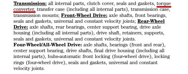
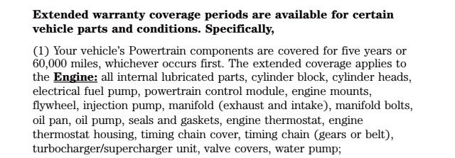
The torque converter is a covered part under the 2019 Powertrain Warranty... Good luck!


-ConnectorC2280GPlug-InLocation-2018EdgeWorkshopManual.jpg.516558bc8061600b590537de6dd88dfb.jpg)