

Haz
-
Posts
1,251 -
Joined
-
Last visited
-
Days Won
325
Content Type
Profiles
Forums
Gallery
Everything posted by Haz
-
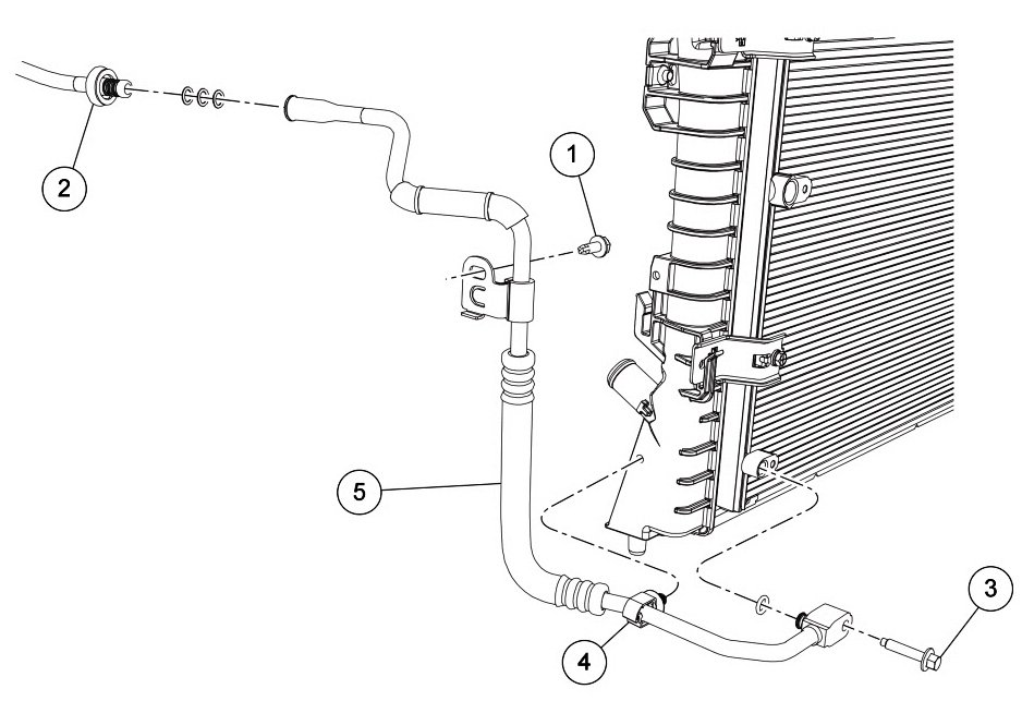
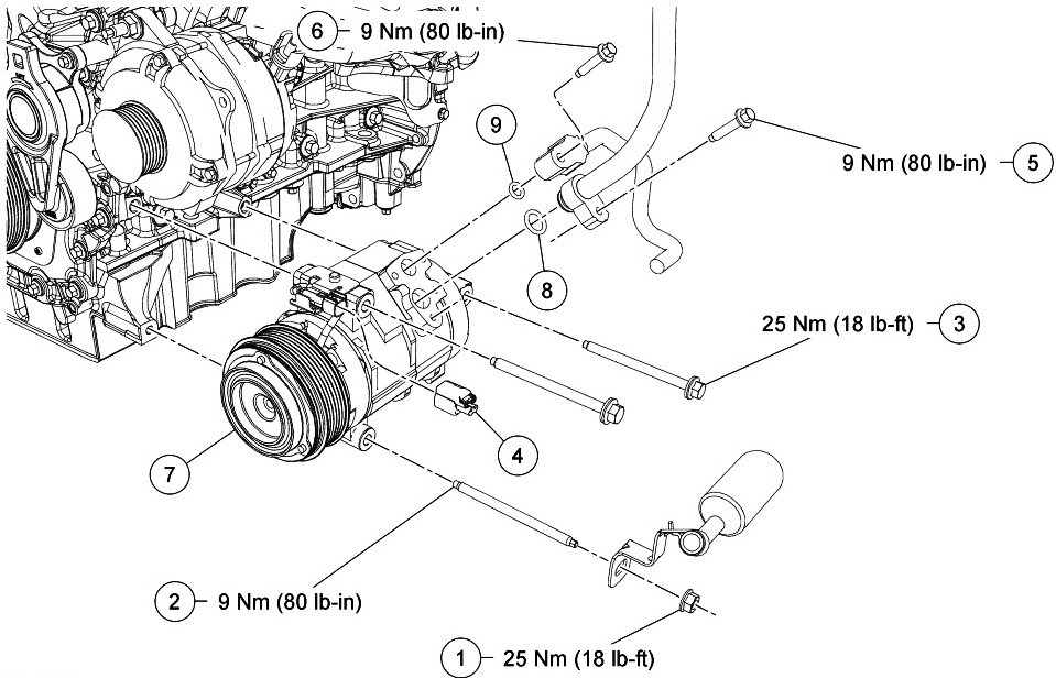
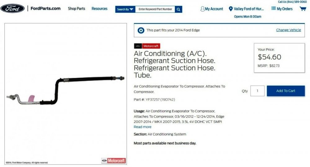
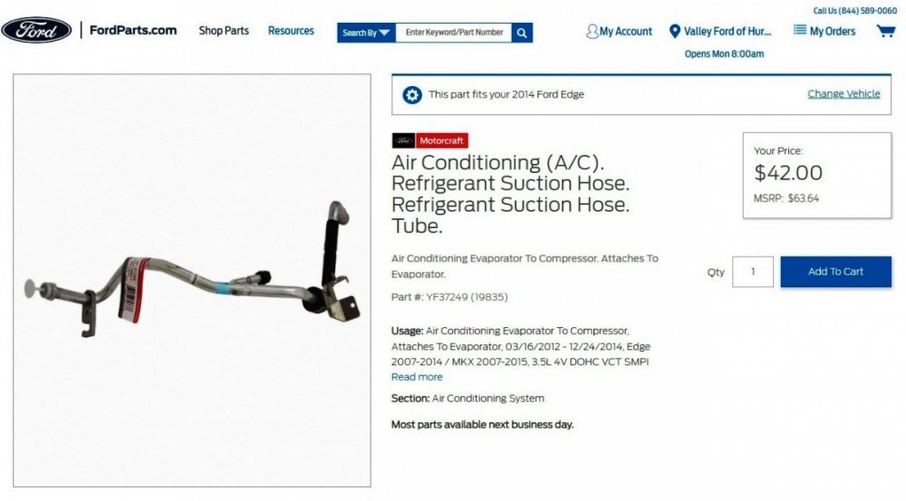
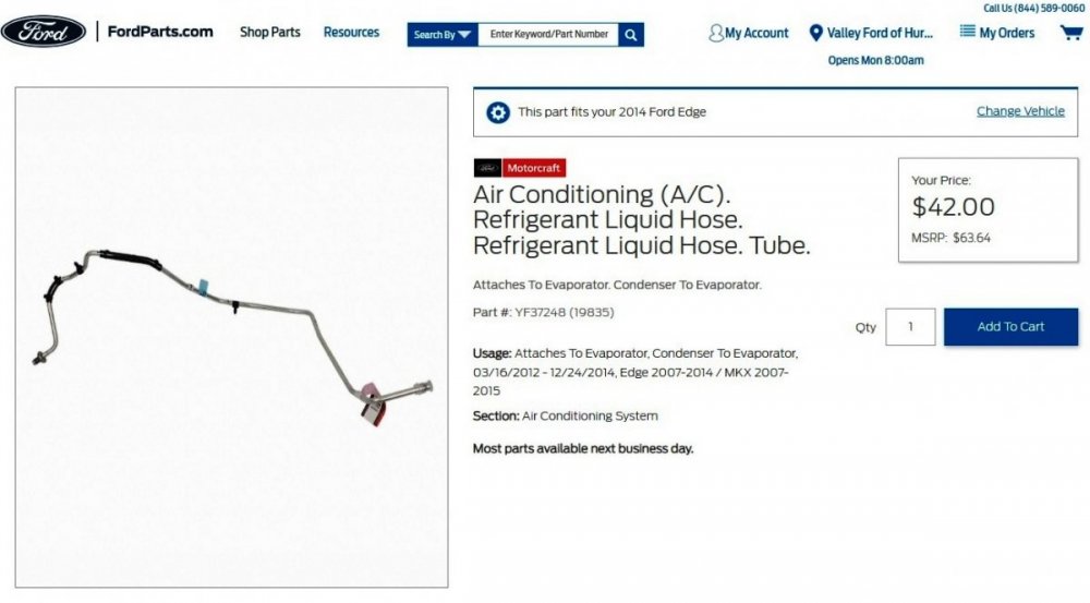
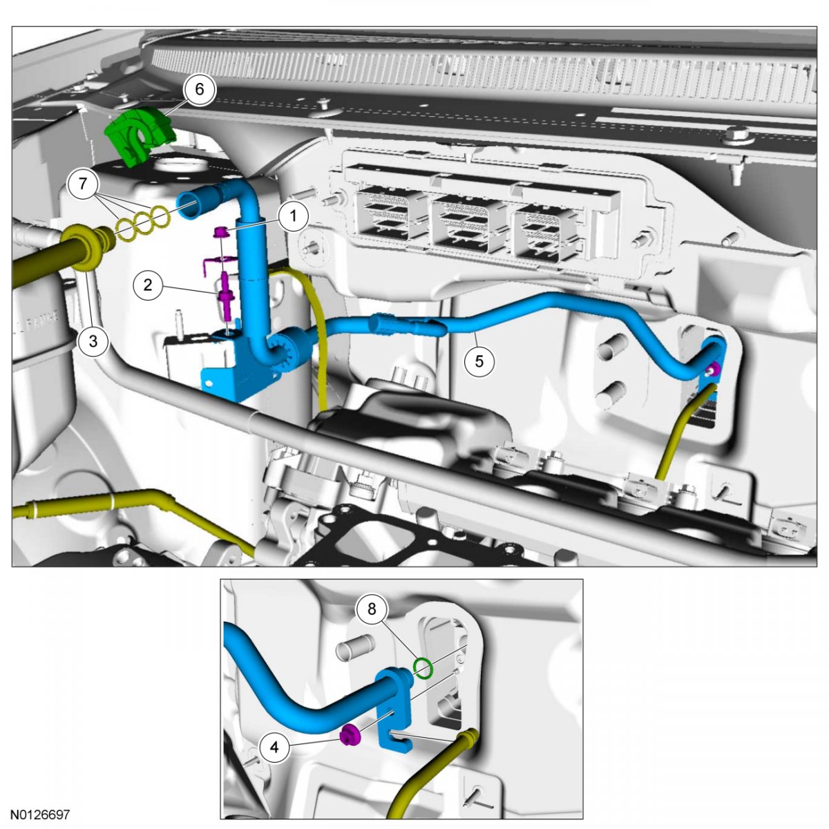
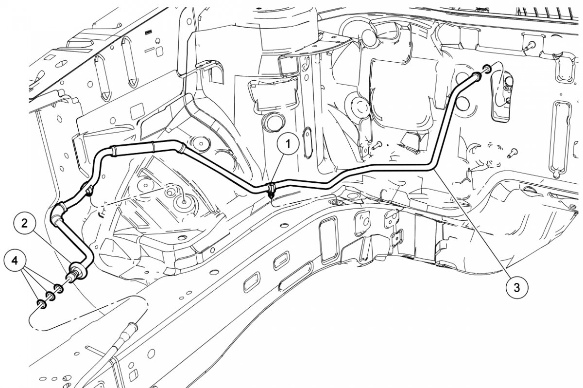
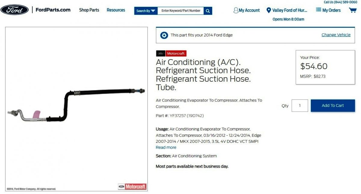
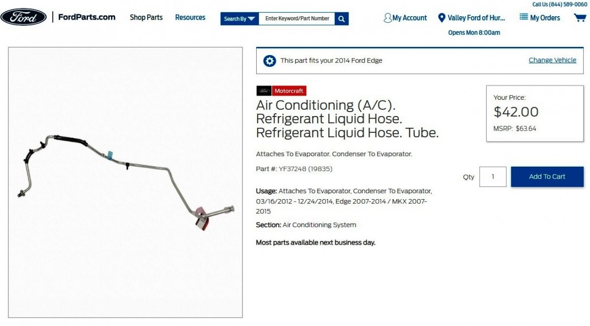
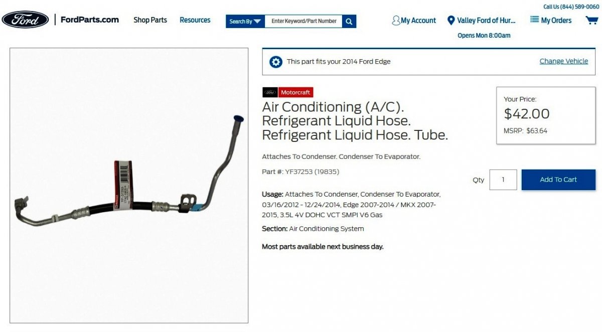
Welcome to the Forum, Mardogs! dabangsta is correct that there are two 2-piece line components conveying refrigerant to and from your Edge's A/C Evaporator... Condenser-Side Condenser-to-Evaporator Line Item Part Number Description 1 W707399 Condenser-to-evaporator line bracket bolt 2 — Condenser-to-evaporator line spring lock coupling (part of 19835) 3 W500215 Condenser outlet fitting bolt 4 W704005 Condenser-to-evaporator line radiator clip 5 19835 Condenser side condenser-to-evaporator line Link this Ford parts website page Evaporator-Side Condenser-to-Evaporator Line Item Part Number Description 1 19D721 Condenser-to-evaporator line clip (2 required) 2 — Condenser-to-evaporator line spring lock coupling (part of 19835) 3 19835 Evaporator side condenser-to-evaporator line 4 19E889 O-ring seal (4 required) Link this Ford parts website page Evaporator-Side Evaporator-to-Compressor Line Item Part Number Description 1 W520413 Ground strap nut 2 N806925 Evaporator outlet line bracket stud bolt 3 — Evaporator outlet line spring lock coupling (part of 19835) 4 W707142 Thermostatic Expansion Valve (TXV) fitting nut 5 19835 Evaporator outlet line 6 19E746 Spring lock coupling secondary latch 7 19E889 O-ring seal (3 required) 8 19E889 O-ring seal Link this Ford parts website page Compressor-Side Evaporator-to-Compressor Line Item Part Number Description 1 W520413 A/C compressor nut 2 W712610 A/C compressor stud 3 W712611 A/C compressor bolt (2 required) 4 12B637 Clutch field coil electrical connector 5 W500215 A/C compressor suction fitting bolt 6 W500215 A/C compressor discharge fitting bolt 7 19703 A/C compressor 8 19E889 Compressor suction fitting O-ring seal 9 19E889 Compressor discharge fitting O-ring seal Link this Ford parts website page Because you've already had a dealer diagnose your Edge's air conditioning issue, and you are not experienced in A/C systems, perhaps you are interested in price-shopping, to ensure that your dealer is being fair to you on the cost of the part(s) you're going to have them replace. If so, the above-pictured webpages are from Ford's own online parts-selling site, though the discounted pricing shown varies by dealer -- in this case, the dealer in my area that I designated offers discount pricing. Other dealers in my area charge list price for parts they supply and install. I mention this because you can use the FordParts website to survey pricing among your local Ford dealers to see if the dealer you may be prepared to do the repair will price-match the discounted parts pricing of a nearby dealer, or another online parts seller. On the other hand, maybe you're prepared to buy the needed part(s) -- which clearly you don't know what you need at the moment, but you can determine that from the dealer. If a problem develops with the part(s) you supply, then it's you -- and not the dealer -- who will be returning the part(s) and possibly paying installation & removal labor cost, since it wasn't the dealer who supplied the faulty or incorrect part(s). I had the fortunate experience of deciding to have my dealership supply an upgraded radiator for my MKX, which arrived and was a leaker out-of-the-box. I was uninvolved while the dealer had to order another radiator, drain the installed coolant, remove the faulty radiator, and complete the radiator upgrade work after the second upgrade radiator arrived. For me, paying the dealer a few more dollars for the upgraded radiator was worth it. Please report back on how things work out for you and your Edge. Good luck!


-
AM Band on Radio Has Ticking Sound
Haz replied to Dmtaurus's topic in Audio, Backup, Navigation & SYNC
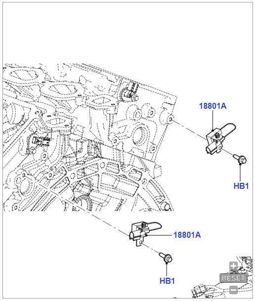
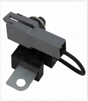
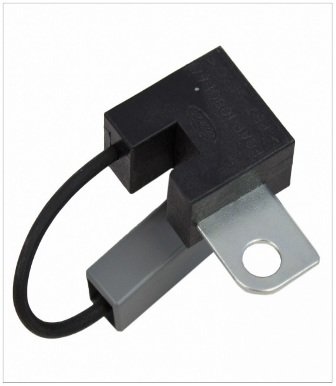
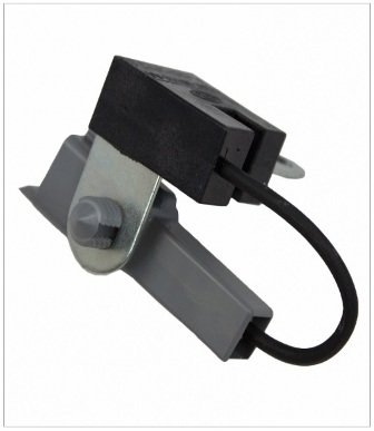
Looking to DILLARD000's 2008 model year, Ford's online parts site shows this listing for engine-mounted capacitors, though it indicates for Gen1/Gen1+ model years, but not for your 2015/Gen2 Edge... Good luck!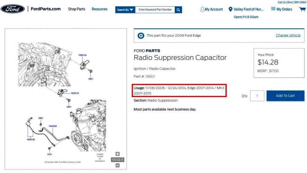
-
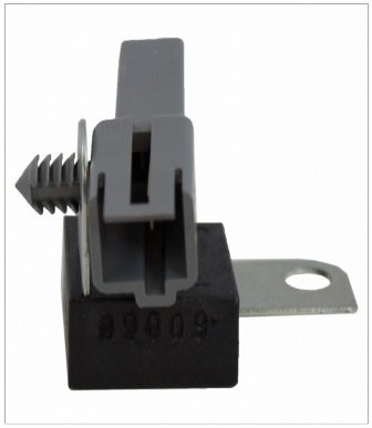
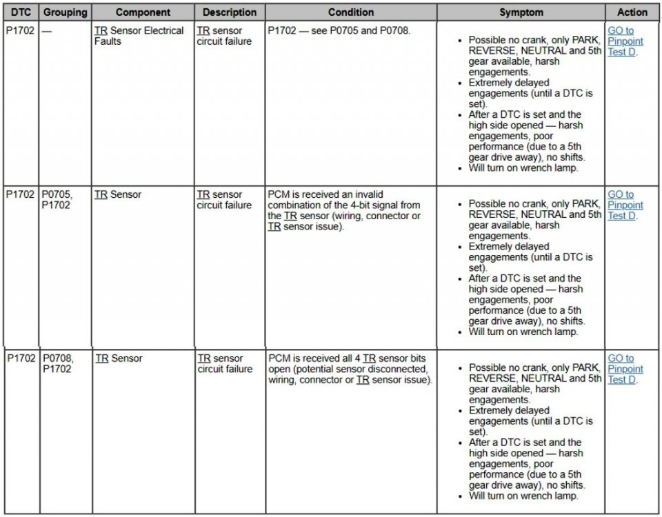
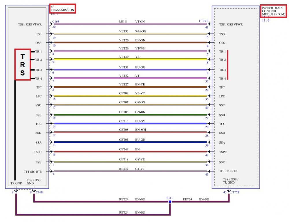
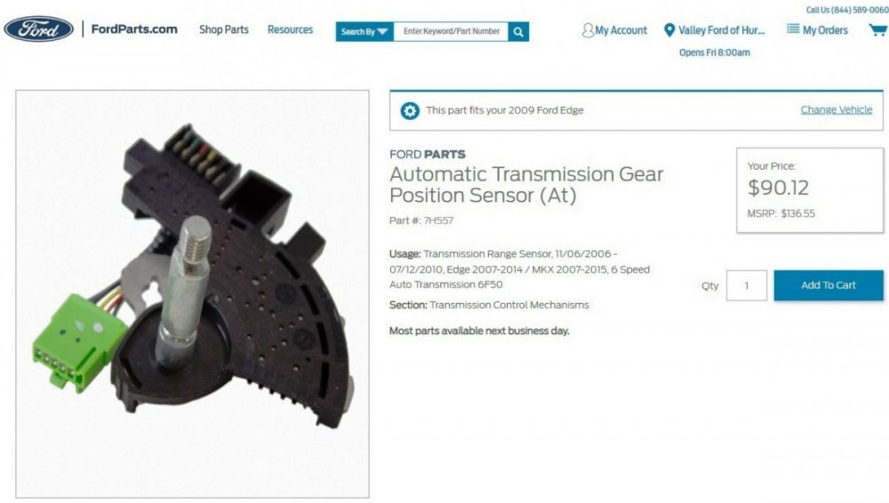
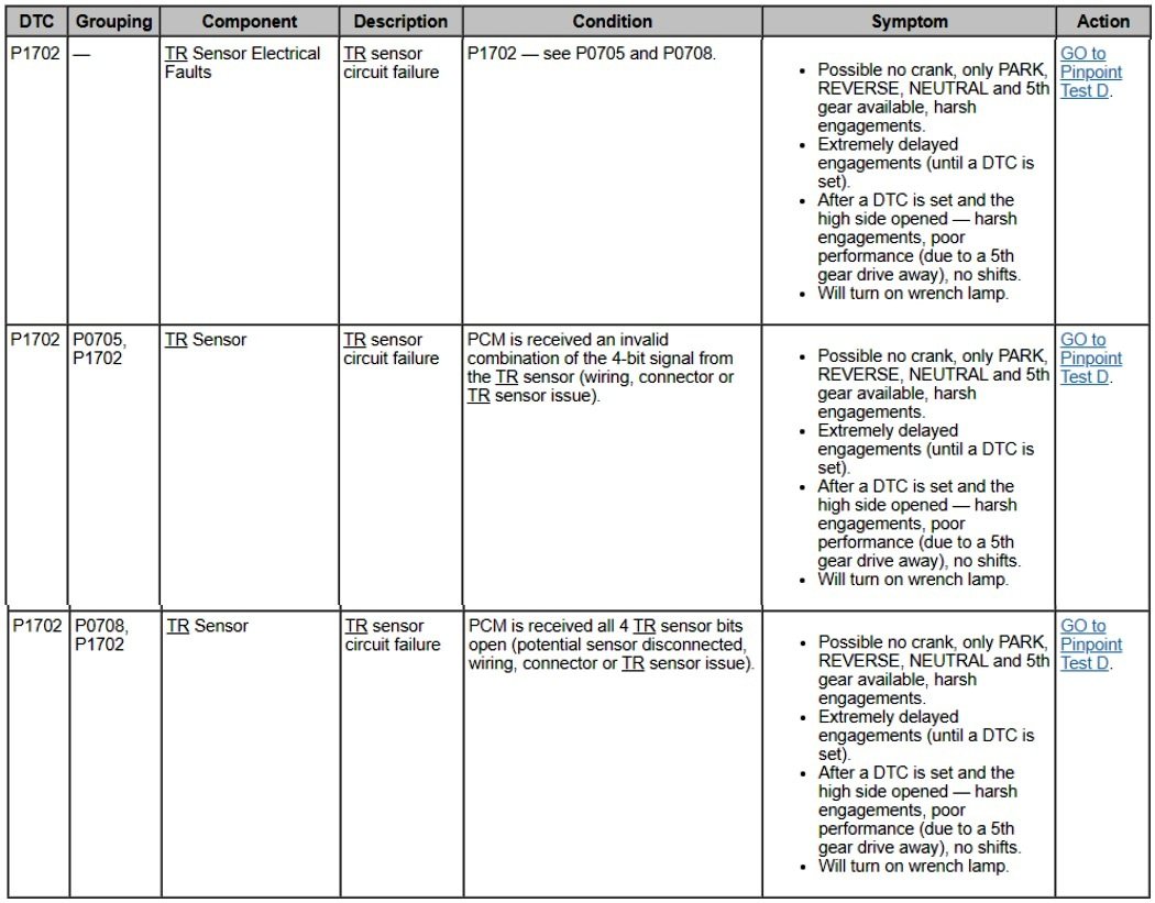
Per the Powertrain Diagnostic Trouble Code (DTC) chart in the 2009 Edge Workshop Manual, your Edge's behavior is consistent with P1702 Transmission Range Sensor circuit failure, which can limit transmission operation to Park, Neutral, Reverse, and 5th Gear only, with harsh engagements... The TR Sensor is internal to the transmission and it communicates with the Powertrain Control Module (PCM), per this TRS-augmented wiring diagram... The advice on how to proceed offered by Forum Moderator 1004ron is a large part of the Workshop Manual's Transmission Range Sensor Pinpoint Test D diagnostic procedure, which is supported by documents detailing Gear Selector Cable Adjustment, inspecting involved external electrical connectors, using an OBDII data link scan tool to monitor TR Sensor PIDs and evaluate TR Sensor & PCM operation, checking the PCM-TR Sensor wiring harness for open circuits and shorted to ground or power circuits. And if all these external tests yield no problems, then the final TR Sensor internal evaluation is conducted after prepping & opening the Transmission's Main Cover. Fulfilling all the external diagnostic steps ensures that you are not needlessly performing the rather extensive work of opening the transmission case to directly inspect & test the TR Sensor and its connector, as described in the TR Sensor Removal and Installation document. Should the TR Sensor fail its direct internal testing, Ford's online parts site offers this replacement... Document download links> 6F50 Transmission, 3.5L Duratec - Electronic Controls Wiring Diagram - 2009 Edge Workshop Manual.pdf Transmission Range Sensor - Pinpoint Test D - 2009 Edge Workshop Manual.pdf 6F50 Transmission - Selector Lever Cable Adjustment - 2009 Edge Workshop Manual.pdf 6F50-6F55 Transmission - Selector Lever Cable Adjustment - 2014 Edge Workshop Manual.pdf 6F50 Transmission, 3.5L Duratec - Electronic Controls Connector C168 Details - 2009 Edge Workshop Manual.pdf 6F50 Transmission, 3.5L Duratec - Electronic Controls Connector C168 Location - 2009 Edge Workshop Manual.pdf POWERTRAIN CONTROL MODULE (PCM) - Connector C175T Details - 2009 Edge.pdf POWERTRAIN CONTROL MODULE (PCM) - Connector C175T Location - 2009 Edge.pdf Powertrain Control Module (PCM) - For Firewall Location Illustration - 2009 Edge Workshop Manual.pdf Transmission Range (TR) Sensor - Removal and Installation - 2009 Edge Workshop Manual.pdf Transmission Range (TR) Sensor Connector Details Pin Number Circuit Function 1 Transmission Range (TR) Ground 2 TR 4 3 TR 3 4 TR 2 5 TR 1 6 Empty Solenoid Body-to-Transmission Range (TR) Sensor Internal Circuit Diagram Connector Details Solenoid Body Main Connector Pin Number TR Sensor Pin Number Circuit Function 4 5 Transmission Range (TR) 1 5 4 TR 2 6 3 TR 3 7 2 TR 4 8 1 TR Ground — 6 Empty You may want to review the documents, and your available tools -- including a scanner and multimeter for the diagnostics, and perhaps get a price for TR Sensor diagnosis, removal & replacement, and then make the decision on how you might proceed. Good luck!
SensorConnectorIllustration.jpg.96b58f77e8ff8d878e2d767ef931dfef.jpg)
SensorInternalCircuitDiagramConnectorsIllustration.jpg.b3d574293ba0fffad81b1c4d6c7992ea.jpg)
-
AM Band on Radio Has Ticking Sound
Haz replied to Dmtaurus's topic in Audio, Backup, Navigation & SYNC
On the 2015 Edge, for all engines, the Powertrain Control Module (PCM) grounds terminate underhood on the vehicle's right hand side at G110, per the below wiring diagram and wiring location illustration... Good luck!-GroundsTerminateatG110-WiringDiagram-2015Edgeallengines.thumb.jpg.8d004a9038d835898be928da8e9d5704.jpg)
-GroundsTerminateatG110-LocationIllustration-2015Edgeallengines.thumb.jpg.391336d3418b8795e7ee5ce7d4a389b5.jpg)
-
Your Edge certainly developed an odd confluence of symptoms. Congratulations on finding a knowledgeable technician to successfully address the issues. Good luck!
-
AM Band on Radio Has Ticking Sound
Haz replied to Dmtaurus's topic in Audio, Backup, Navigation & SYNC
Partial diagnostic test from the 2015 Edge Workshop Manual, and supplemental document download links below... PINPOINT TEST A: POOR RECEPTION OR CONTINUOUS SEEK OR SCAN - AM (AMPLITUDE MODULATION) / FM (FREQUENCY MODULATION) A1 CHECK THE AUDIO SYSTEM RECEPTION WITH THE ENGINE RUNNING Operate the audio system in AM / FM mode. Check the reception with the engine running, and with the engine off. Is poor reception only present with the engine running? Yes GO to A2 No GO to A4 A2 CHECK THE GENERATOR Ignition OFF. NOTICE: Do not allow the generator B+ cable terminal to make contact with a conductive surface. Failure to follow this instruction may result in personal injury or damage to the vehicle. Disconnect: Generator B+ Cable C102C. (3.5L Duratec shown, 2.0L EcoBoost similar) Start the engine. Operate the audio system in AM / FM mode. Is the reception OK? Yes INSTALL a new generator. • For vehicles with the 2.0L EcoBoost (184kW/250PS), REFER to: Generator - 2.0L EcoBoost (184kW/250PS) – MI4 (414-02 Generator and Regulator, Removal and Installation). • For vehicles with the 2.7L EcoBoost (238kW/324PS), REFER to: Generator - 2.7L EcoBoost (238kW/324PS) (414-02 Generator and Regulator, Removal and Installation). • For vehicles with the 3.5L Duratec (212kW/278PS), REFER to: Generator - 3.5L Duratec (212kW/278PS) (414-02 Generator and Regulator, Removal and Installation). No GO to A3 A3 CHECK THE IGNITION CIRCUITS Ignition OFF. Connect: Generator B+ Cable C102C. (3.5L Duratec shown, 2.0L EcoBoost similar) Visually inspect the engine compartment and make sure all ignition coils are correctly and securely connected, and that there are no visible cracks in the coil housings. Inspect all the wiring harnesses and connectors for damaged insulation and loose or broken conditions. Are the ignition components OK? Yes USE a jumper cable to temporarily ground various parts of the vehicle (examples include: engine, fenders, quarter panels, body sheet metal) to the frame. When the noise is eliminated, PROVIDE a permanent ground where necessary. No REPAIR the ignition system as necessary. Document download links> Ignition Coil-On-Plug - Removal and Installation - 2.0L EcoBoost - 2015 Edge Workshop Manual.pdf Ignition Coil-On-Plug - Removal and Installation - 3.5L Duratec - 2015 Edge Workshop Manual.pdf Good luck!

-
Document download links> Air Cleaner Outlet Pipe - Removal and Installation - 2.0L EcoBoost - 2016 Edge Workshop Manual.pdf Heated Oxygen Sensor (HO2S) - Removal and Installation - 2.0L EcoBoost - 2016 Edge Workshop Manual.pdf Catalyst Monitor Sensor - Removal and Installation - 2.0L EcoBoost - 2016 Edge Workshop Manual.pdf Heated Oxygen Sensor (HO2S) - Wiring Diagram - 2.0L EcoBoost - 2016 Edge Workshop Manual.pdf Heated Oxygen Sensor (HO2S) - Connectors C1631 & C1632 Locations - 2.0L EcoBoost - 2016 Edge Workshop Manual.pdf Universal Heated Oxygen Sensor (HO2S) #11 - Connector C1631 Details - 2.0L EcoBoost - 2016 Edge Workshop Manual.pdf Heated Oxygen Sensor (HO2S) #12 - Connector C1632 Details - 2.0L EcoBoost - 2016 Edge Workshop Manual.pdf Powertrain Control Module (PCM) - Connector C1361B Details - 2.0L EcoBoost - 2016 Edge.pdf Heated Oxygen Sensor (HO2S) - Description and Operation - Ford Powertrain Control-Evaporative Diagnosis Manual - 2016 Gasoline.pdf TSB 18-2212 - 2.0L EcoBoost - Illuminated Malfunction Indicator Lamp (MIL) with Diagnostic Trouble Code (DTC) P0036 - Built On Or Before 12-Mar-2018.pdf Rear Driveshaft - Removal and Installation - 2016 Edge Workshop Manual.pdf Muffler and Tailpipe - Removal and Installation - 2.0L EcoBoost - 2016 Edge Workshop Manual.pdf Good luck!
-
Document download links> Camshaft Position Sensors - Wiring Diagram - 3.5L - 2008 Edge.pdf Powertrain Control Module (PCM) - Connector C175E Details - 3.5L - 2008 Edge.pdf Powertrain Control Module (PCM) - Connector C175E Location - 3.5L - 2008 Edge.pdf Camshaft Position Sensors - Inline Connectors C139 Male & Female Details - 3.5L - 2008 Edge.pdf Camshaft Position Sensors - Inline Connectors C139 Male & Female Location - 3.5L - 2008 Edge.pdf Camshaft Position Sensors - Inline Connectors C139 + Camshaft Sensor Locations - 3.5L - 2008 Edge.pdf Good luck!
-
Welcome to the Forum, Booker ! Document download links> 6-Speaker Audio Wiring Diagram - 2019 Edge.pdf 9-Speaker Audio Wiring Diagram #1 - 2019 Edge.pdf 9-Speaker Audio Wiring Diagram #2 - 2019 Edge.pdf 12-Speaker Audio Wiring Diagram #1 - 2019 Edge.pdf 12-Speaker Audio Wiring Diagram #2 - 2019 Edge.pdf 12-Speaker Audio Wiring Diagram #3 - 2019 Edge.pdf 12-Speaker Audio Wiring Diagram #4 - 2019 Edge.pdf AUDIO FRONT CONTROL MODULE (ACM) - Connector C240A Details - 2019 Edge.pdf AUDIO FRONT CONTROL MODULE (ACM) - Connector C240A Location - 2019 Edge.pdf Good luck!
-
Welcome to the Forum, fcasontoo ! Please be aware that some procedural instructions in the following document may appear on the page preceding the illustration relating to the described action-step... Document download links> Generator - 2.0L EcoBoost - Removal and Installation - 2019 Edge Workshop Manual.pdf Air Conditioning Compressor Belt - 2.0L EcoBoost - Removal and Installation - 2019 Edge Workshop Manual.pdf Battery Disconnect and Connect - General Procedures - 2019 Edge Workshop Manual.pdf Good luck!
-
One additional document download link, to supplement the files shared offline... Cabin Heater Coolant Pump - 2.0L EcoBoost - Removal and Installation - 2015 Edge Workshop Manual.pdf Good luck!
-
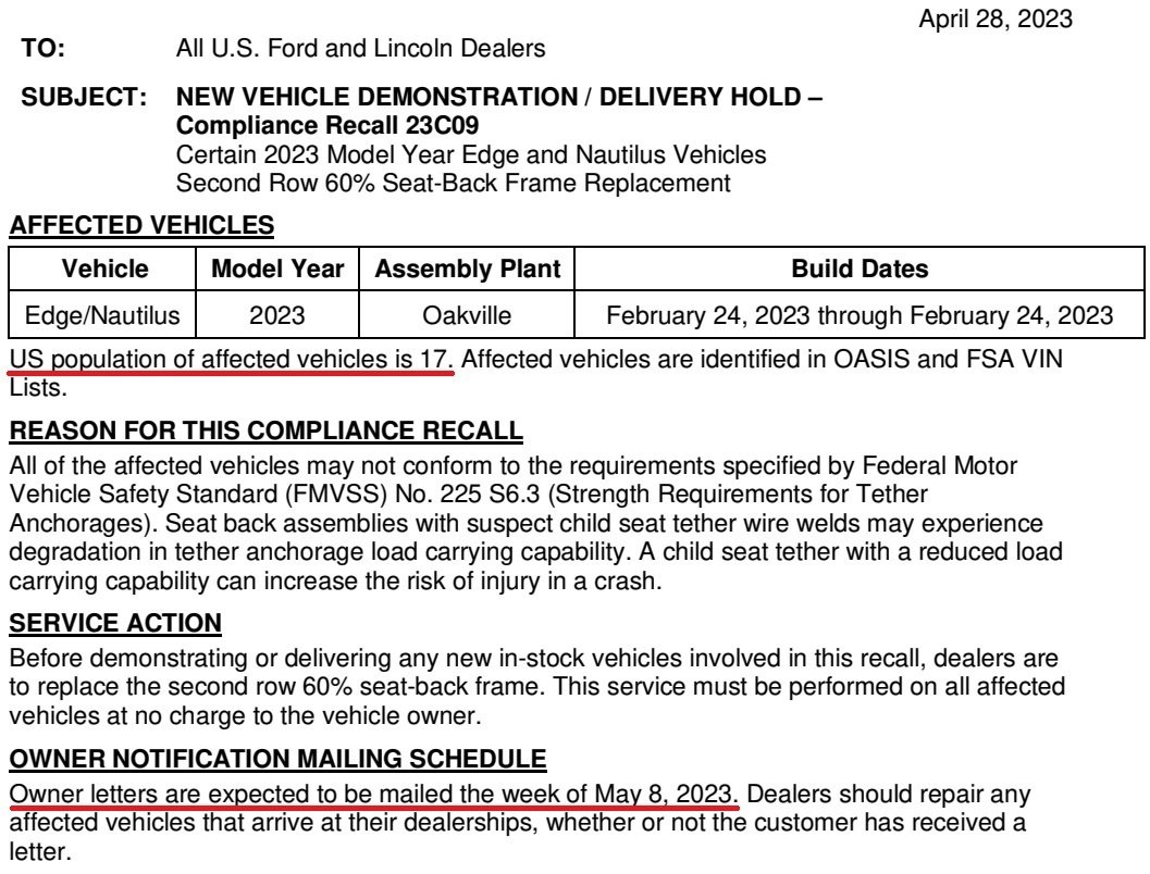
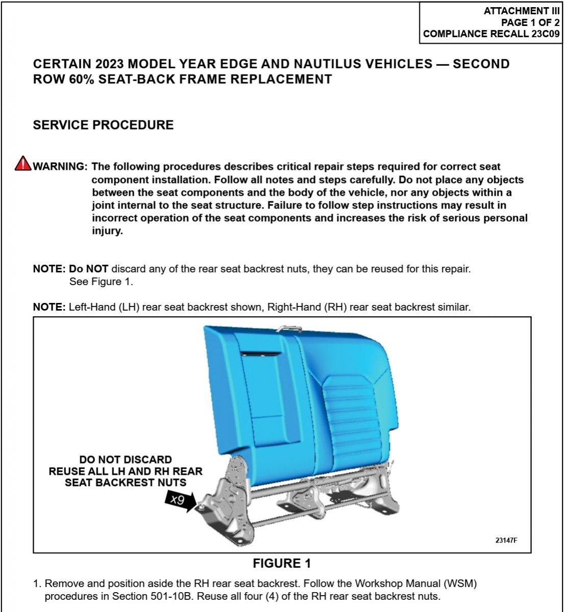
Dealer bulletin and technical repair info released, affected population reduced to 17 vehicles...


- 1 reply
-
- 3
-

-
You may want to consider submitting a sample of the drained engine oil to Blackstone Labs, to see how much and what types of metal it may contain. Forum member macbwt has many informative oil testing videos on his MACTFordEdge YouTube page. Good luck!
-
These documents may also be helpful... Power Distribution-BCM - Wiring Diagram - Cell 013, Page 2 - 2012 Edge Workshop Manual.pdf COOLING FAN MODULE - Wiring Diagram - 2012 Edge Workshop Manual.pdf COOLING FAN MODULE - Connector C1554 Details - 2012 Edge Workshop Manual.pdf COOLING FAN MODULE - Connector C1554 Locator - 2012 Edge Workshop Manual.pdf Cooling Fan and Shroud - 3.5L, 3.7L - 2012 Edge Workshop Manual.pdf Good luck!
-
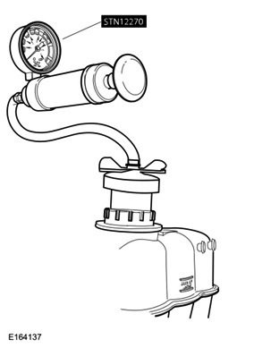
Welcome to the Forum, JayTheWorldsHero! TSB 22-2229 - 2015-2018 Edge + Other Models, 2.0L EcoBoost - Coolant In Cylinders, White Exhaust Smoke And_Or Illuminated MIL.pdf (document download link) describes these various applicable warranty coverages... Warranty Status: Eligible under provisions of New Vehicle Limited Warranty (NVLW)/Emissions Warranty/Service Part Warranty (SPW)/Special Service Part (SSP)/Extended Service Plan (ESP) coverage. Limits/policies/prior approvals are not altered by a TSB. NVLW/Emissions Warranty/SPW/SSP/ESP coverage limits are determined by the identified causal part and verified using the OASIS part coverage tool. For repairs covered by the NVLW, completion of the procedure outlined in this TSB does not require obtaining Prior Approval or completion of a Cost Cap. Your Edge's 7-year/100,000 miles Certified Pre-Owned (CPO) Powertrain coverage falls under the TSB's "Extended Service Plan (ESP)" coverage category, and your Edge's CPO Powertrain generic covered- parts list should be... Engine: Cylinder block and internal lubricated parts, seals and gaskets, the cylinder heads, manifold (exhaust, intake and bolts), factoryinstalled turbocharger/supercharger units, timing chain (gears or belt), fywheel, valve covers, oil pan, timing chain cover, oil pump, water pump, thermostat, thermostat housing. (Exceptions: fuel injection components are not covered.) Transmission: Transmission case and all internal parts, including torque converter and transfer case (all internal parts), seals, gaskets and transmission control module. Front-Wheel Drive: Front drive housing and rear axle housing for AWD (including all internal parts), universal and constant velocity joints, axle shafs, locking rings (four-wheel-drive vehicles), seals and gaskets, and automatic front locking hubs (four-wheel drive). Rear-Wheel Drive: Drive axle housings and front axle housing for 4x4 (including all internal parts), universal and constant velocity joints, axle shafts, seals and gaskets, and driveshafts. As dabangsta mentioned, a 5-hour coolant system pressure test exhibiting a 4 psi leak-down is among the TSB's necessary qualifying symptoms. If you're a curious do-it-yourself owner -- or your dealer's Service scheduling is seriously backed up -- your neighborhood auto parts store may offer a cooling system pressure tester through their tool loaning program that may require a refundable deposit equal to the tool's full purchase price. If that interests you, the following is Ford's procedure from the 2018 Edge Workshop Manual... Cooling System Pressure Test WARNING: Always allow the engine to cool before opening the cooling system. Do not unscrew the coolant pressure relief cap when the engine is operating or the cooling system is hot. The cooling system is under pressure; steam and hot liquid can come out forcefully when the cap is loosened slightly. Failure to follow these instructions may result in serious personal injury. NOTE: Vehicles have a pressure relief cap on the degas bottle and no radiator cap. Turn the engine OFF. Check the engine coolant level and adjust as necessary. Remove the degas bottle cap. Inspect the degas bottle cap and degas bottle for any issues that would cause improper sealing, such as for cross-threading, burrs, damaged o-ring, etc. If any issues are found, INSTALL a new cap and/or degas bottle. Attach the Pressure Tester (Stant 12270 or equivalent) and adaptor (Snap-On TA53 or equivalent), to the degas bottle cap. The cap must hold pressure of 145 kPa +/- 21 kPa (21 PSI +/- 3 PSI). If any issues are found, INSTALL a new cap. Attach the Pressure Tester (Stant 12270 or equivalent) and adaptor (Snap-On TA52, AST ASSFZ-47, Redline RDL95-0750 or equivalent) to the degas bottle. NOTICE: Do not pressurize the cooling system beyond the maximum pressure listed in the specifications table in this section, or cooling system components can be damaged. NOTE: If the plunger of the pressure tester is pressed too fast, an erroneous pressure reading will result. To pressurize the engine cooling system, slowly press the plunger of the pressure test pump and increase the pressure to between 124 - 138 kPa (18 - 20 PSI). Observe the gauge reading for approximately 2 minutes. Pressure should not drop during this time. If the pressure drops within this time, inspect for leaks and repair as necessary. Allow the vehicle to sit for a minimum of 5 hours, or overnight. NOTE: 2-4 psi of pressure drop is normal and expected after engine cool down. If the pressure drops more than the expected range of 2-4 psi and no leaks are found and the pressure drops, the leak may be internal to the engine. Inspect the coolant for engine oil and the engine oil for coolant. REFER to: Engine (303-00 Engine System - General Information, Diagnosis and Testing). If the pressure does not drop, remove the cooling system Pressure Tester and adaptor from degas bottle. Install the degas bottle cap until it contacts the hard stop. And finally, before your Edge reaches its CPO 100,000 mile Powertrain coverage limit, you have the opportunity to renew with FordProtect PowertrainCare coverage without any inspection requirement. Document download links> Cooling System Pressure Test - 2018 Edge Workshop Manual.pdf Ford Certified Pre-Owned (CPO) Consumer Brochure - October 2018.pdf FordProtect PowertrainCARE Brochure - October 2022.pdf Good luck!
-
Adding Adaptive suspension to my ST
Haz replied to johnmarkp's topic in Brakes, Chassis & Suspension
The Vehicle Dynamics Control Module (VDM) processes an impressive array of inputs to do its job... Document download links> Vehicle Dynamic Suspension - System Operation and Component Description - 2019 Nautilus Workshop Manual.pdf Vehicle Dynamic Suspension - Component Location - 2019 Nautilus Workshop Manual.pdf Vehicle Dynamic Suspension - Wiring Diagram, Cell 041 Page 1 - 2019 Nautilus Workshop Manual.pdf Vehicle Dynamic Suspension - Wiring Diagram, Cell 041 Page 2 - 2019 Nautilus Workshop Manual.pdf Vehicle Dynamic Suspension - Wiring Diagram, Cell 041 Page 3 - 2019 Nautilus Workshop Manual.pdf Vehicle Dynamics Control Module (VDM) - Connector C4396C Details - 2019 Nautilus Workshop Manual.pdf Vehicle Dynamics Control Module (VDM) - Connector C4396D Details - 2019 Nautilus Workshop Manual.pdf Vehicle Dynamics Control Module (VDM) - Connectors C4396C & C4396D Location - 2019 Nautilus Workshop Manual.pdf Vehicle Dynamics Control Module (VDM) - Removal and Installation - 2019 Nautilus Workshop Manual.pdf Vehicle Dynamic Suspension - Diagnosis and Testing - 2019 Nautilus Workshop Manual.pdf Front Suspension Height Sensor - Removal and Installation - 2019 Nautilus Workshop Manual.pdf Front Strut and Spring Assembly - Removal and Installation - 2019 Nautilus Workshop Manual.pdf Rear Suspension Height Sensor - Removal and Installation - 2019 Nautilus Workshop Manual.pdf Rear Shock Absorber - Removal and Installation - 2019 Nautilus Workshop Manual.pdf Good luck! -
Windshield Replacement
Haz replied to 1004ron's topic in Glass, Lenses, Lighting, Mirrors, Sunroof (BAMR), Wipers
The 2015-2023 Edge Workshop Manuals all provide a single, generalized Fixed Glass procedure, carrying a 11/21/2019 revision date... Document download links> Fixed Glass - General Procedures - 2017 Edge Workshop Manual.pdf Interior Rear View Mirror - Removal and Installation - 2017 Edge Workshop Manual.pdf Image Processing Module A (IPMA) Camera Heated Windshield Element - Removal and Installation - 2017 Edge Workshop Manual.pdf A-Pillar Trim Panel - Removal and Installation - 2017 Edge Workshop Manual.pdf B-Pillar Trim Panel - Removal and Installation - 2017 Edge Workshop Manual.pdf Headliner, Lowering - Removal and Installation - 2017 Edge Workshop Manual.pdf Good luck! -
Windshield Replacement
Haz replied to 1004ron's topic in Glass, Lenses, Lighting, Mirrors, Sunroof (BAMR), Wipers
The additional details in the 2019-2023 procedure are preferred, I would say... 2015-2018 Edge Workshop Manual (Procedure revision date: 04/20/2015) Camera Alignment Camera alignment is required for the lane keeping alert and lane keeping aid to function correctly. The procedure is initiated using the scan tool and requires about 10 minutes of driving above 64 km/h (40 mph) to complete. If the alignment is unsuccessful, check the interior mirror for proper installation. The IPMA camera alignment procedure should be performed when any of the following occur: Windshield replacement Change in tire size Suspension repair, alignment or modifications Front air bag deployment Interior mirror replacement Document download link> Lane-Keeping System - System Operation and Component Description - 2017 Edge Workshop Manual.pdf 2019-2023 Edge Workshop Manual (Procedure revision date: 04/16/2021) Camera Alignment Camera alignment is required for the lane keeping alert and lane keeping aid to function correctly. The procedure is initiated using the diagnostic scan tool and requires about 10 minutes of driving above 64 km/h (40 mph) on a flat, straight road with highly visible lane markings to complete. NOTE: The alignment completion is indicated on the diagnostic scan tool. If the alignment is unsuccessful, check the IPMA for proper installation. NOTE: The FRONT CAMERA MALFUNCTION - SERVICE REQUIRED message in the IPC disappears when the system is aligned. The IPMA camera alignment procedure should be performed when any of the following occur: Windshield replacement Change in tire size Suspension repair or alignment Front air bag deployment Document download link> Lane-Keeping System - System Operation and Component Description - 2019 Edge Workshop Manual.pdf While I suspect the Safelite technician will have a corporate alignment procedure, you're at least equipped to amend with Ford guidance if required. Likewise, the Safelite technician may already have a preferred alignment Drive Cycle path, though you might also enjoy being prepared with a proper straightaway... From CalculatorSoup (page link) Good luck!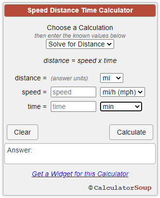
-
Supplementing dabangsta's comments... Start your Edge and watch the Tire Pressure dash light, which, if it's flashing, should flash for 70-seconds, followed by the Tire Pressure dash light being continuous-on until the Edge is shutoff. Take your Edge for a continuous at-least 20-minutes-long drive at higher-than 32k/h (20 mph) to ensure the Tire Pressure Monitor System is given the opportunity to to gather enough Tire Sensor data to correct the Tire Pressure Monitor System Fault that the flashing Tire Pressure dash light indicates. After completing that at-least 20-minute Drive Cycle, shut-off the Edge, and then restart it to see if that eliminates the 70-second flashing Tire Pressure dash light -- and possibly the continuous-on Tire Pressure dash light. If the flashing Tire Pressure dash light does return, it most likely indicates at least one Tire Sensor is not reporting -- the sensor on the wheel the Repair Shop replaced. If the Tire Pressure dash light issue continues to be an issue, it's your choice on whether to wait the additional day they asked, before contacting them. You might print a copy of the Tire Pressure Monitoring System (TPMS) - Diagnosis and Testing - 2013 Edge Workshop Manual.pdf and take it with you. They may be interested by it, or, they may say they know everything they need to know -- though they did release the Edge back to you with a non-functioning Tire Pressure Monitor System. From the previously shared Tire Pressure Monitoring System (TPMS) - Diagnosis and Testing - 2013 Edge Workshop Manual.pdf, with emphasis added... TPMS Warning Indicator Flashes The TPMS warning indicator flashes for 70 seconds, then remains ON continuously when the ignition switch is turned to the ON position and 1 or more of the following conditions exists: Tire Pressure Sensor Fault — The message center displays TIRE PRESSURE SENSOR FAULT when a TPMS sensor is malfunctioning. GO to Symptom Chart. No communication with the BCM . The TPMS indicator is illuminated when the IPC has not received any signals from the BCM for more than 5 seconds. The message center displays TIRE PRESSURE MONITOR FAULT. GO to Symptom Chart. Tire Pressure Monitor Fault — The message center displays TIRE PRESSURE MONITOR FAULT when the TPMS is malfunctioning or communication with the IPC has been lost. GO to Symptom Chart. The TP_STAT PID can be used to determine why the TPMS warning indicator is flashing. Tire Pressure Monitoring System (TPMS) PID Definitions and Intermittent Troubleshooting TPMS Status PID The TPM monitors the TPMS status. The current status can be viewed by accessing the TPMS status PID : TPMS_STAT using the scan tool. This helps identify the current system status and may aid in diagnosing the system. The PID has 4 valid states: TPMS_STAT = SENSOR FAULT. If the module has not received the tire pressure status from 1 to 3 TPMS sensors for 20 minutes when the vehicle speed is above 32 km/h (20 mph), the PID displays SENSOR FAULT. TPMS_STAT = SYSTEM FAULT. If the module has not received the tire pressure status from all 4 TPMS sensors for 20 minutes and the vehicle speed is above 32 km/h (20 mph), the PID displays SYSTEM FAULT. TPMS_STAT = LOW. If the module has detected that at least 1 TPMS sensor is reporting low tire pressure, the PID displays LOW. TPMS_STAT = SYSTEM ACTIVE. If the TPMS is functioning normally, the PID displays SYSTEM ACTIVE. Good luck!
-
Document download link> Tire Pressure Monitoring System (TPMS) - Diagnosis and Testing - 2013 Edge Workshop Manual.pdf Scanning your Edge may yield a Diagnostic Trouble Code (DTC) in the above-linked document that points to a specific issue, but likely is damaged sensor, wrong sensor, no sensor. Pinpoint Test D - Tire Pressure Monitoring System (TPMS) Warning Indicator On Continuously and Message Center Displays LOW TIRE PRESSURE Normal Operation The Tire Pressure Monitor (TPM) module monitors the tire pressure of all 4 road tires. The wheel-mounted tire pressure sensors transmit data via radio frequency signals to the TPM module. The TPM module is a radio receiver that collects the tire pressure data from the Tire Pressure Monitoring System (TPMS) tire pressure sensors. The data is then sent to the Body Control Module (BCM) where a predetermined pass/fail criteria is applied. The TPMS sensor radio transmissions are sent approximately once every 60 seconds when the vehicle speed exceeds 32 km/h (20 mph). The BCM compares each TPMS sensor transmission against a low-pressure limit. If it has been determined that the tire pressure has fallen below this limit, the BCM communicates this on the vehicle communication bus to the Instrument Panel Cluster (IPC) . The IPC then illuminates the TPMS warning indicator and displays the appropriate message(s) in the message center . This symptom can also be caused by a spare tire currently being used in place of a road tire. Make sure the spare tire is not currently in use. This pinpoint test is intended to diagnose the following: Tire pressure not set to specifications listed on the Vehicle Certification (VC) label Spare tire currently in use TPMS sensor(s) PINPOINT TEST D : TPMS WARNING INDICATOR ILLUMINATES CONTINUOUSLY AND MESSAGE CENTER DISPLAYS LOW TIRE PRESSURE NOTE: Use only the Digital Tire Pressure Gauge any time tire pressures are measured to be sure that accurate values are obtained. NOTE: If a warranty case is opened for an actual TPMS fault, document and include the actual tire pressure data in all warranty communications. D1 CHECK FOR SPARE TIRE IN USE NOTE: The spare tire is not programmable even if it is equipped with a TPMS sensor. If a damaged road wheel is located in the trunk, the sensor may still be recognized by the TPMS as low. Make sure the spare tire is not currently in use. To restore TPMS functionality, repair the damaged road wheel and re-mount it to the vehicle. Check spare tire location. Is the spare tire in use? Yes REPAIR and REMOUNT the wheel to the vehicle. REFER to Wheel and Tire in this section. ADJUST tire pressures to the required pressure as defined on the Vehicle Certification (VC) label located in the driver door jam. TEST the system for normal operation. No GO to D2. D2 CHECK FOR LOW TIRE PRESSURE Using the Digital Tire Pressure Gauge, measure and record the tire pressure in all 4 road tires. Adjust the pressure for those found to be below the specification listed on the VC label. Activate each sensor at least twice with the training tool or customer activation tool to make sure the module gets the latest tire pressure data. Refer to Tire Pressure Monitoring System (TPMS) Sensor Activation or drive the vehicle for at least 2 minutes above 32 km/h (20 mph) to clear the low pressure warning. Do not train the sensors at this time. Has the TPMS warning indicator gone out? Yes The system is operating correctly at this time. The cause was low tire pressure. No GO to D3 D3 CHECK FOR STUCK TPMS SENSOR Ignition OFF. Connect the scan tool. Ignition ON. Enter the following diagnostic mode on the scan tool: BCM DataLogger . Monitor and record the following tire pressure PIDs : TPM_PRES_LF TPM_PRES_RF TPM_PRES_LRO TPM_PRES_RRO Using the Digital Tire Pressure Gauge, measure the actual tire pressures. Compare the tire pressure PIDs with the actual tire pressures. Do the compared tire pressure values match within ± 5 psi? Yes REFER to Section 413-01 to diagnose the TPMS warning indicator light. No INSTALL a new TPMS sensor(s). REFER to Tire Pressure Monitoring System (TPMS) Sensor in this section. Clearly, the repair shop should correct the problem, hopefully, without you contacting the snowplow company owner / insurance company. Good luck!
-
2011 edge backup camera looks to be not standard
Haz replied to gonesail's topic in Audio, Backup, Navigation & SYNC
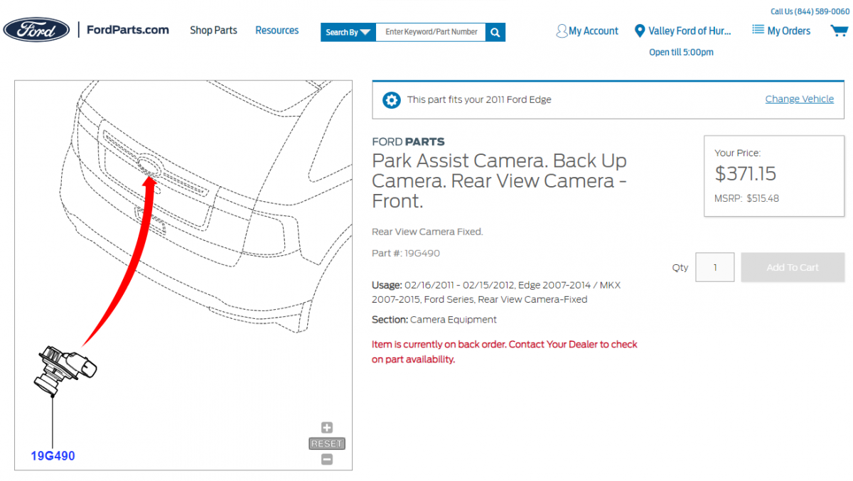
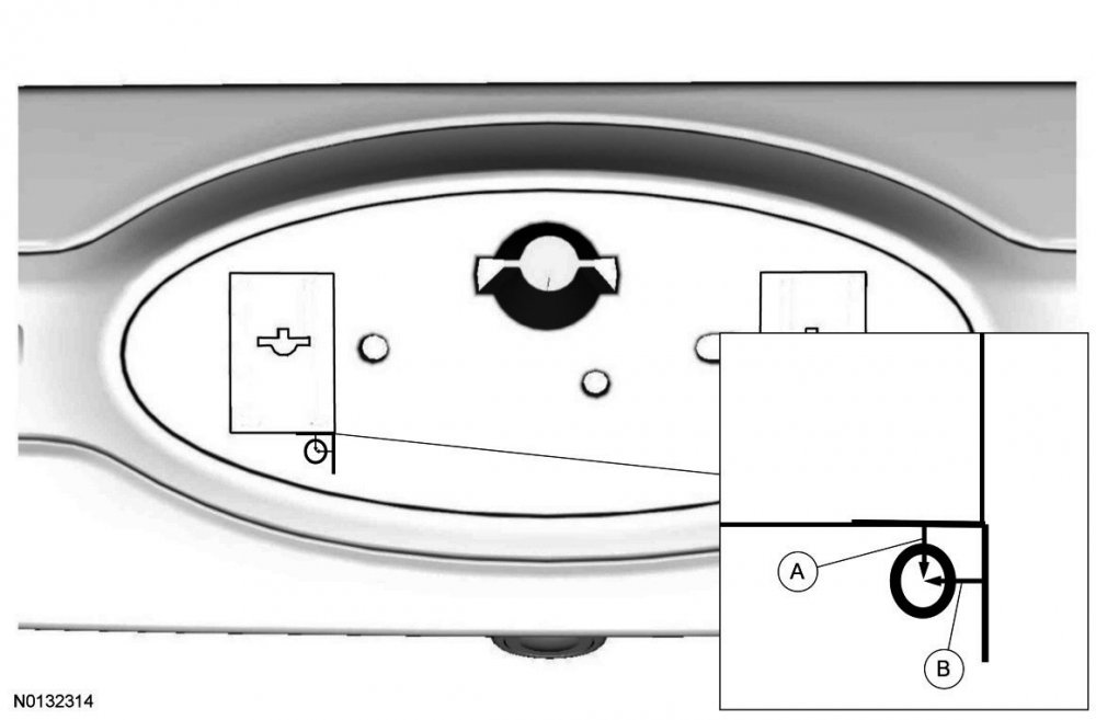
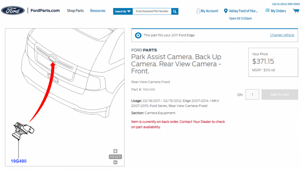
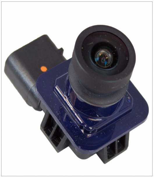
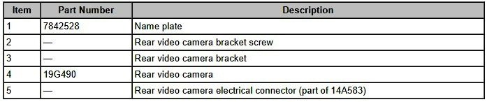
At first glance, I was inclined to agree, but it's really the standard camera assembly. From the 2011 Workshop Manual... Video Camera - Removal and Installation Edge Removal Edge Remove the rear liftgate applique. For additional information, refer to Section 501-08. [See Document download links>, below...] Carefully remove the name plate from the rear liftgate applique and discard. Drill a 6.35 mm (0.25 in) hole through the rear lift gate applique as indicated. A: measure down 3.175 mm (0.125 in) from the left side embossed edge. B: measure over 6.35 mm (0.25 in) from the left side embossed edge. Loosen the rear video camera bracket screw (T-20) through the access hole. Remove the rear video camera bracket and the rear video camera. Disconnect the electrical connector. Installation Edge Install the rear video camera and install the rear video camera bracket. Connect the electrical connector. Tighten the rear video camera bracket screw through the access hole. Cut a piece of mylar tape (19E523) 12.7 mm (0.5 in) long and cover the access hole. Install a new name plate onto the rear liftgate applique. Install the rear liftgate applique. For additional information, refer to Section 501-08. [See Document download links>, below...] NOTE: If the camera was replaced, the rear video camera guidelines will not display if the rear video camera is not configured. Configure the rear video camera following the instructions on the scan tool. Document download links> Video Camera - Removal and Installation - 2011 Edge-MKX Workshop Manual.pdf Applique — Liftgate - Removal and Installation - 2011 Edge Workshop Manual.pdf Liftgate Trim Panel - Removal and Installation - 2011 Edge Workshop Manual.pdf Liftgate Trim Panel - Page 1 Enhanced Illustration - 2011 Edge Workshop Manual.pdf From Ford's parts-selling website (link to page)... If you'd prefer replacing your faulty camera with a used part, instead of new, you could try using the Car-Part.com salvage yard search engine... Pricing for a used replacement backup camera in my area ranges from $135-to-$250. Good luck!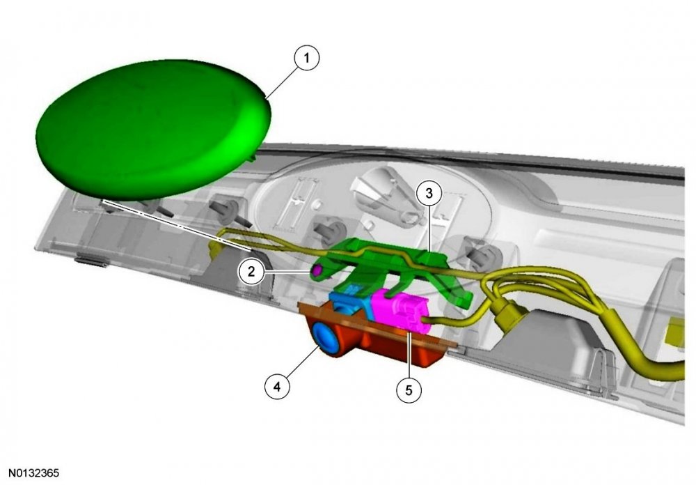
-
From Seeking Alpha... Ford to import Lincoln Nautilus SUVs to sell in the U.S. Apr. 18, 2023 8:47 AM ET Ford Motor Company plans to import into the U.S. the reworked Lincoln Nautilus SUV made in Hangzhou, China. The model year 2024 SUV will feature a new electric-gasoline hybrid powertrain and will be the first model Ford imports from China. The Nautilus SUV is already sold in China under a joint venture that Ford has with Chinese automaker Changan Automobile. The decision could attract attention from politicians with Ford already under some scrutiny for a battery plant it is building in Michigan with licensed technology from China’s Contemporary Amperex Technology Co. Ltd. Lincoln President Dianne Craig said the Detroit-based company had no choice but to import the vehicles from China because the American and Canadian plants all have other plans set. "In this case, it's a good use of resources," noted S&P Global Mobility analyst Stephanie Brinley on the development. "Without importing, Lincoln does not get the product, and the brand needs products between now and when its EVs arrive," she noted. Perhaps not surprisingly, Ford's media release on the 2024 Nautilus does not mention its planned importation from China.
-
From the 2012 Edge Workshop Manual... Principles of Operation Power Steering The power steering system uses a vane-type pump to move the fluid from the reservoir to the steering gear and through the rest of the steering hydraulic system. The power steering pump is mounted to the engine and driven by the engine accessory drive belt. Power steering fluid flows into the pump from the reservoir. The power steering fluid is trapped between the pump vanes and moved to the high-pressure side of the pump, creating a flow of fluid. The restriction of this flow by the steering gear creates the pressure that provides the steering assist. A combined pressure relief/flow valve is built into the pump to control the maximum pressure and flow provided to the steering system. This action prevents damage to the system and provides the correct level of assist during all engine speeds. While under pressure, the power steering fluid flows through the high-pressure power steering line to the steering gear. The fluid exits the gear and flows through the return line, cooler and finally to the reservoir. The reservoir slows the fluid, allows air to escape and filters the fluid before returning it to the pump. Steering System Symptom Definitions Lack of Assist or Inconsistent Assist Lack of assist or inconsistent assist is experienced when the steering wheel effort is higher than normal. Hard steering can remain constant through the full turn or occur near the end of a turn. It is important to know the difference between hard steering/lack of assist and poor returnability/sticky steering. Hard steering or lack of assist can result from either hydraulic or mechanical conditions. It is extremely important to know if this concern occurs during driving or during high-effort parking maneuvers. Poor Returnability/Sticky Steering Poor returnability and sticky steering is used to describe the poor return of the steering wheel to center after a turn or steering correction is completed. Pinpoint Test A: Steering Has Lack of Assist or Inconsistent Assist NOTE: Hard steering or lack of assist is experienced when the steering wheel effort is higher than normal. Hard steering can remain constant through the full turn, occur near the end of a turn or differ right to left. This pinpoint test is intended to diagnose the following: Power steering fluid contamination Steering gear Power steering pump Power steering hoses PINPOINT TEST A : STEERING HAS LACK OF ASSIST OR INCONSISTENT ASSIST A1 CHECK FOR POWER STEERING FLUID CONTAMINATION Check the power steering fluid for contamination. Is the power steering fluid contaminated? Yes FLUSH the power steering system. REFER to Power Steering System Flushing in this section. CHECK the system for normal operation. If assist concern still exists, GO to A2. No GO to A2. A2 CHECK THE STEERING ASSIST WITH THE ENGINE RPM RAISED NOTICE: Do not hold the steering wheel at the stops for an extended amount of time. Damage to the power steering pump may occur. Set the engine at 2,100 rpm and turn the steering wheel fully to the left and right. Is steering assist fully restored to normal with the engine rpm raised? Yes INSTALL a new power steering pump. REFER to Section 211-02. No GO to A3. A3 CHECK FOR A CHANGE OF ASSIST ON LEFT AND RIGHT TURNS With the engine at idle, turn the steering wheel fully to the left and to the right. Does the steering assist change when turning from right to left? Yes INSTALL a new steering gear. REFER to Section 211-02. No GO to A4. A4 CHECK THE STEERING LINES AND HOSES FOR RESTRICTIONS Inspect the steering lines and hoses for damage, kinks or restrictions. Are the steering lines or hoses damaged, kinked or restricted? Yes INSTALL new lines or hoses as necessary. No GO to A5. A5 MONITOR THE ENGINE RPM CHANGES NOTICE: Do not hold the steering wheel at the stops for an extended amount of time. Damage to the power steering pump may occur. NOTE: Make sure that the vehicle is on a flat dry surface, all accessories are in the OFF position and that the steering system is at normal operating temperature. Connect the scan tool. Start the engine. With the engine at idle, raise the power steering fluid temperature to 74-80°C (165-176°F) by rotating the steering wheel fully to the left and right several times. Enter the following diagnostic mode on the scan tool: DataLogger — PCM . Monitor the Engine Revolutions Per Minute (RPM) PID while turning the steering wheel quickly to the left stop position and then to the right stop position. Note the engine rpm during the turns. Does the engine rpm change (even temporarily) more than 30 rpm when turning the steering wheel? Yes INSTALL a new steering gear. REFER to Section 211-02. No INSTALL a new power steering pump. REFER to Section 211-02. Good luck!
-
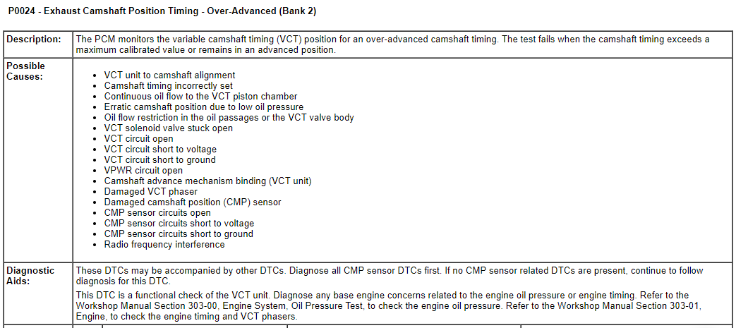
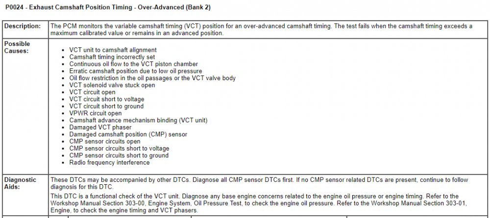
Welcome to the Forum! All Diagnostic Trouble Codes (DTCs) share the same Possible Causes, and Diagnostic steps. From the Ford Powertrain Control/Emissions Diagnosis Manual - 2013 Gasoline... Document download links> Pinpoint Test HK - Variable Camshaft Timing (VCT) - Powertrain Control-Emissions Diagnosis Manual - 2013 Gasoline.pdf Variable Camshaft Timing Solenoid - Wiring Diagram - 3.5L-3.7L TIVCT - 2013 Edge Workshop Manual.pdf Variable Camshaft Timing 11 (VCT11) Solenoid - Connector C1451 Details - 3.5L-3.7L TIVCT - 2013 Edge Workshop Manual.pdf Variable Camshaft Timing 12 (VCT12) Solenoid - Connector C1452 Details - 3.5L-3.7L TIVCT - 2013 Edge Workshop Manual.pdf Variable Camshaft Timing 21 (VCT21) Solenoid - Connector C1610 Details - 3.5L-3.7L TIVCT - 2013 Edge Workshop Manual.pdf Variable Camshaft Timing 22 (VCT22) Solenoid - Connector C1611 Details - 3.5L-3.7L TIVCT - 2013 Edge Workshop Manual.pdf Powertrain Control Module (PCM) - Connector C175E Location - 2013 Edge Workshop Manual.pdf Variable Camshaft Timing 11 & 12 (VCT11-12) Solenoid - Connector C1451 & C1452 Location Illustration - 3.5L-3.7L TIVCT - 2013 Edge Workshop Manual.pdf Variable Camshaft Timing 21 & 22 (VCT21-22) Solenoid - Connector C1610 & C1611 Location Illustration - 3.5L-3.7L TIVCT - 2013 Edge Workshop Manual.pdf Variable Camshaft Timing (VCT) Oil Control Solenoid - Removal and Installation - 3.5L Duratec.pdf Valve Cover, LH - Removal and Installation - 3.5L Duratec - 2013 Edge Workshop Manual - RP.pdf Valve Cover, RH - Removal and Installation - 3.5L Duratec - 2013 Edge Workshop Manual - RP.pdf Good luck!


-
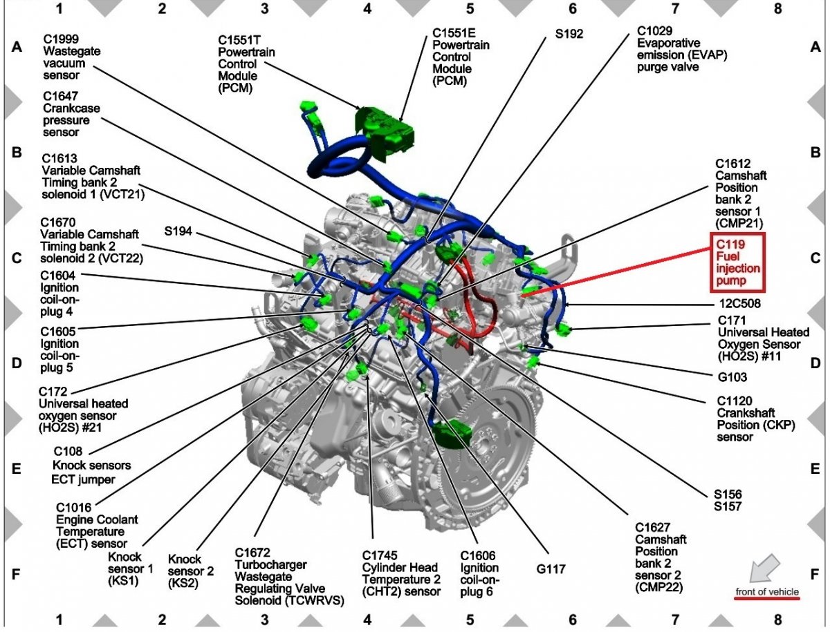
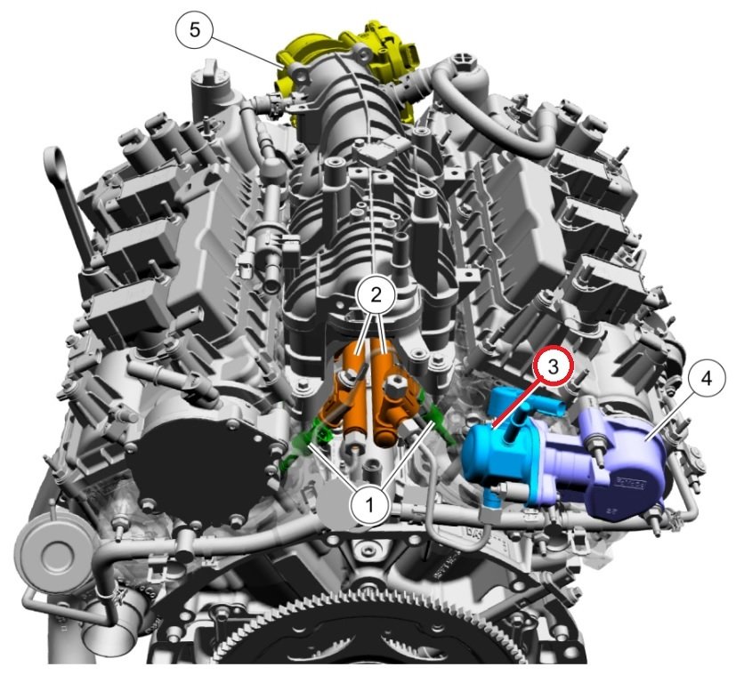
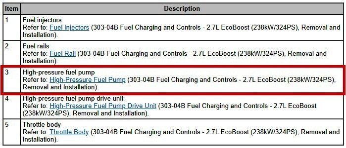
The noise described as "not detrimental to engine function, [having] no effect on engine durability, [and] an operating characteristic of these engines" in SSM 51465 - 2019-2023 Various Vehicles - 2.0L/2.3L EcoBoost - Light To Moderate Ticking Type Noise At Idle (600-700 RPM) is attributed to those EcoBoost engines' High Pressure Fuel Pump. Perhaps it's that same component you're hearing on your 2.7L EcoBoost, as shown in the 2019 Edge Workshop Manual... 2.7L EcoBoost Fuel Charging and Controls - Component Location Document download link> High Pressure Fuel Pump - Removal and Installation - 2019 Edge Workshop Manual.pdf Good luck!


-GroundsTerminateatG110-WiringDiagram-2015Edgeallengines.jpg.0b8e648db4546e74089714c889d5f524.jpg)
-GroundsTerminateatG110-LocationIllustration-2015Edgeallengines.jpg.cbaf00cc01fe679dcaf80ce030732478.jpg)