Haz
-
Posts
1,476 -
Joined
-
Last visited
-
Days Won
394
Content Type
Profiles
Forums
Gallery
Everything posted by Haz
-
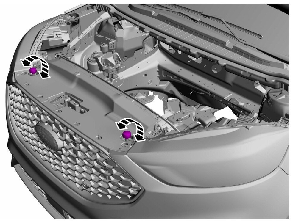
Welcome to the Forum, @pjtaxi ! From the 2020 Edge Workshop Manual... Hood - Removal and Installation - 2020 Edge Workshop Manual.pdf Hood Alignment - General Procedures - 2020 Edge Workshop Manual.pdf Hood Latch - Removal and Installation - 2020 Edge Workshop Manual.pdf Active Grille Shutter - Removal and Installation - 2020 Edge Workshop Manual.pdf Front Bumper Cover - Removal and Installation - 2020 Edge Workshop Manual.pdf Good luck!
-
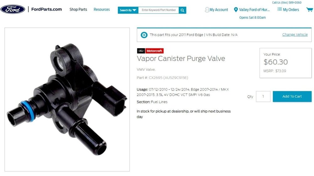
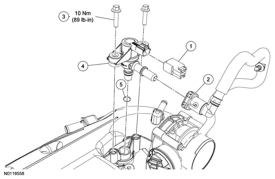
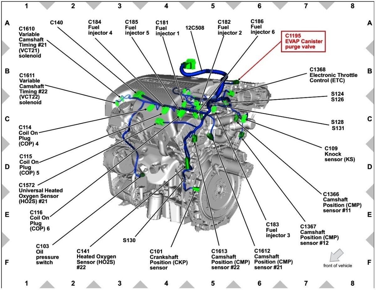
Purge Valve procedure and illustrations from 2011 Edge Workshop Manual... Link to this FordParts webpage Evaporative Emission Canister Purge Valve - Removal and Installation - 2011 Edge Workshop Manual.pdf Evaporative Emission Canister Purge Valve - Enhanced Image - 2011 Edge Workshop Manual.pdf Evaporative Emission Canister Purge Valve - Connector C1195 Location - 2011 Edge.pdf Quick Connect Coupling - General Procedures - 2011 Edge Workshop Manual.pdf Good luck!


-
What have you done to/with your Edge/MKX today?
Haz replied to WWWPerfA_ZN0W's topic in Accessories & Modifications
Edge Workshop Manual sections on 2.0L & 2.7L EcoBoost Charging Systems, Battery Load Shed, and Generator Specifications... Charging System - 2.0L EcoBoost - System Operation and Component Description - 2020 Edge Workshop Manual.pdf Charging System - 2.7L EcoBoost - System Operation and Component Description - 2020 Edge Workshop Manual.pdf Battery Load Shed - Description and Operation - 2020 Edge Workshop Manual.pdf Generator and Regulator - Specifications - 2020 Edge Workshop Manual.pdf Good luck! -
GENERAL SERVICE BULLETIN Various Vehicles - Diagnosing Turbocharger Oil And Coolant Leaks 24-7022 14 March 2024 This bulletin supersedes 20-7025. Reason for update: revise the vehicle model years affected. Summary This bulletin covers the diagnosis of oil and coolant leaks observed on the external and internal surfaces of the turbocharger. Service Information Reference the following sections within the WSM for complete information on oil and coolant leak diagnostics. Sections 303-03 and 303-04 are engine specific. • 303-00 Engine System / General Information / Diagnosis and Testing • 303-03 Engine Cooling / Diagnosis and Testing • 303-04 Fuel Charging and Controls - Turbocharger / Diagnosis and Testing Two key notes from the WSM regarding this topic: NOTE: The turbocharger oil supply tube is located on the top of the turbocharger. Many leaks from the turbocharger oil supply tube will look like they are turbocharger oil leaks, as the oil will accumulate in the v-band and drip off the bottom of the turbocharger. After replacing the turbocharger oil supply tube, clean the outside of the turbocharger to avoid false diagnosis of a leaking turbocharger. NOTE: It is normal for a small amount of combustion gas to pass into the crankcase. This gas is scavenged into the air intake system through the PCV system, which incorporates a crankcase vent oil separator. Some engine oil, in the form of a vapor is carried into the air intake system with the blow-by gases (this engine oil also contributes to valve seat durability). This means that oil will collect inside the air intake components and the turbocharger. This is not an indication that the turbocharger oil seal has failed. The turbocharger oil seal will generally not fail unless the bearings fail first, which will cause the turbocharger to become noisy or seize. Do not install a new turbocharger due to oil inside the turbocharger or the air intake components. If a leak is detected in the oil supply or return tubes or connections, locate and rectify the source. Do not install a new turbocharger due to an oil leak. Overview of observed oil / coolant on external surfaces of a gasoline engine turbocharger: • Oil and coolant may be observed on the external surfaces of turbochargers. This is not an indication of a faulty turbocharger. • Staining or wet oil / coolant dripping may be present on the lower point of the turbocharger v-band. - Figures 1-2 show likely locations to observe oil or coolant. Figure 1 Figure 2 • Oil and coolant on the external surfaces of the turbocharger may come from several sources - Turbo oil feed/drain line joints - Turbo coolant drain/feed line joints - Engine oil fill port drips - Other engine sealing leaks above the turbocharger • Any oil / coolant leaks from turbo connections / areas higher on the engine can be funneled through the v-band making it look like the turbo itself is leaking. This is not an indication of a faulty turbocharger. Figure 3 - Turbo v-band clamp (oil/coolant catch basin) Figure 4 - Oil/coolant may fill the trough created by the inside of the v-band (arrow) from other sources and spill over at the lowest point. This can create the false appearance that the turbocharger is leaking. Figure 5 - Example of typical staining • Oil with dye in it may appear under black light on the turbocharger as a bright yellow mark. Figure 6 shows a typical indication of oil on the external surface of the turbocharger from an oil feed line leak. This is not an indication of a faulty turbocharger. - Shown below is the same location of the turbo under normal light (Figure 6) and black light (Figure 7). Figure 6 Figure 7 Actions • Do not replace gasoline engine turbochargers for oil or coolant leaks without first following the appropriate diagnostic procedures within the WSM. Overview of acceptable locations for oil or coolant on the internal surfaces of a gasoline engine turbocharger: • A film of oil in the turbine or compressor housing is a normal byproduct of engine operation. • Staining or wet oil / coolant drips may be present in the turbine outlet, compressor inlet, and compressor outlet. • All these conditions are normal in a turbocharged engine and are not an indication of a faulty turbocharger. Figure 8 - Oil film / staining in turbine housing outlet to catalyst Figure 9 - Oil film / staining in the compressor housing inlet from the fresh air tube Figure 10 - Oil film / staining in compressor outlet to high pressure tube Actions: • Do not replace gasoline engine turbochargers for oil or coolant leaks without first following the appropriate diagnostic procedures within the WSM. © 2024 Ford Motor Company All rights reserved. NOTE: This information is not intended to replace or supersede any warranty, parts and service policy, workshop manual (WSM) procedures or technical training or wiring diagram information.
-
GENERAL SERVICE BULLETIN Various Vehicles - Turbocharged Engines - Normal Turbocharger Sounds And Turbocharger Repairs 24-7023 14 March 2024 This bulletin supersedes 20-7092. Reason for update: revise the vehicle model years affected Summary To assist with determining when turbocharger repairs are necessary, follow the Service Information. Service Information Turbocharged engines may make a variety of sounds although the turbocharger is functioning properly. Some examples of normal turbocharger noises that do not indicate a durability concern include, but are not limited to: • Rattle noise at idle or during light load conditions • Whine noise that will track with engine speed • Whoosh noise on acceleration • Noise with wastegate actuation (creak, squawk) Axial or radial play in the turbo shaft is normal unless there is evidence of compressor wheel contact with the compressor housing. Do not compare turbocharger noises to other vehicles as part tolerances, engine calibrations, and other factors can cause sound characteristics to vary between otherwise similar vehicles. It is very rare for a turbo to have a problem without setting a DTC. Diagnostics should only be performed for turbocharger noise concerns if other symptoms are present in addition to the noise. The turbo should only be replaced if the pinpoint test for a DTC directs to replace the turbo or there is visible damage to the compressor wheel from compressor housing contact. Refer to applicable WSM and/or PC/ED Manual diagnostic routines when DTCs or additional symptoms are present. © 2024 Ford Motor Company All rights reserved. NOTE: This information is not intended to replace or supersede any warranty, parts and service policy, workshop manual (WSM) procedures or technical training or wiring diagram information.
-
SSM 52365 2024 Lincoln Nautilus - Non-Black Label - Rear Interior Door Panels Not Equipped With Upper Ambient Surface Lamps 2024 Lincoln Nautilus non-Black Label vehicles are not equipped with upper ambient surface lamps on the rear interior door panels. This is not a misbuild condition and installation of ambient light panels is not a warrantable repair. Do not submit a claim for this condition.
-
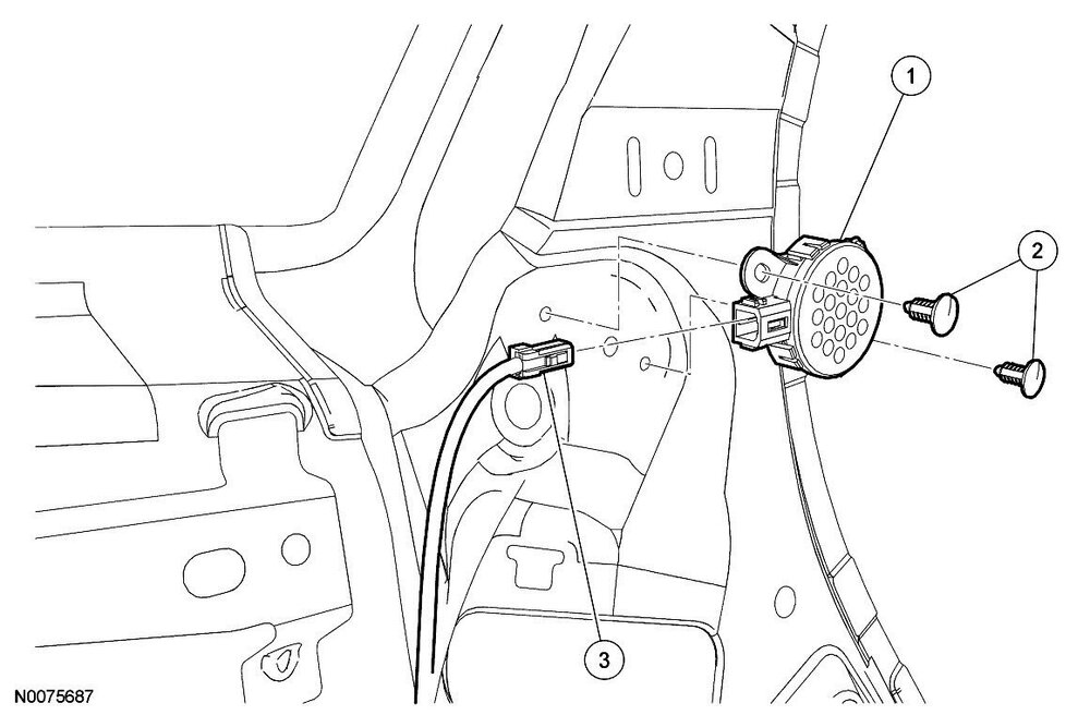
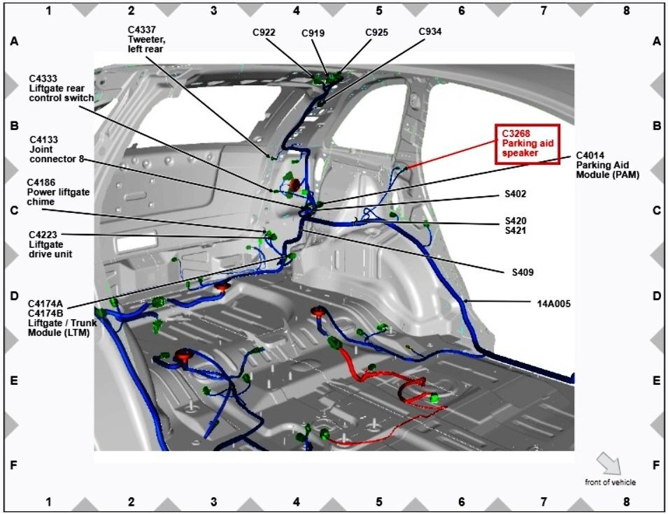
From the 2008 Edge Workshop Manual... Document download links> Parking Aid Speaker - Removal and Installation - 2008 Edge Workshop Manual.pdf Parking Aid Speaker - Removal and Installation - ENHANCED IMAGE - 2008 Edge Workshop Manual.pdf Parking Aid Speaker - Connector C3268 Location - 2008 Edge Workshop Manual.pdf Parking Aid Module (PAM) - Removal and Installation - 2008 Edge Workshop Manual.pdf Parking Aid Module - Connector C4014 Location - 2008 Edge Workshop Manual.pdf Quarter Trim Panel - Removal and Installation - 2008 Edge Workshop Manual.pdf Good luck!
-
Ford Edge and a Queen Bed Frame
Haz replied to Gayenell's topic in Interior, A.C., Heat, Interior Trim
Welcome to the Forum, Gayenell ! A variety of Edge cargo space dimensions are available for all model years from this CarSpecs.org webpage. Good luck! -
P1450 code Purge Valve fixed but code comes back again one month later?
Haz replied to fairlaniac's topic in 2.0L EcoBoost
From the 2015 Ford Powertrain Control/Emissions Diagnosis Manual, a multi-model/multi-engine diagnostic reference... Document download link> Pinpoint Test HX - EVAP System and Monitor- 2015 Ford PC-ED Manual.pdf Good luck!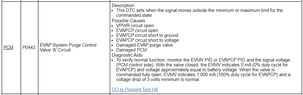
-
Replacing the Ford EDGE instrument panel
Haz replied to Yurez's topic in Accessories & Modifications
720-03-01: ⭐xxx-xxxx-xxxx I expect the U0103 DTC is the result of the 2020 IPC looking for its previous 2020 Edge's Shift By Wire (SBW) rotary shifter, but your 2018 Edge is not equipped with Shift By Wire (SBW), so the desired As-Built value ⭐ should include SBW Disabled. Per the IPC As-Built values you shared above, The present value of ⭐ is A, indicating SBW Enabled. A=SBW Enabled, SD Disabled, SPLT Enabled, SC North America To achieve SBW Disabled while maintaining the other three attributes in the combination. try... 4=SBW Disabled, SD Enabled, SPLT Disabled, SC North America With ⭐=4, hopefully, the U0103 DTC will not reoccur after you clear it from the Gear Shift Module (GSM). Good luck! -
Replacing the Ford EDGE instrument panel
Haz replied to Yurez's topic in Accessories & Modifications
Shift By Wire (SBW) Side Detect (SD) Sidemarker/Position Lamp Telltale (SPLT) Speedometer Cal (SC) Location 720-03-01: *xxx-xxxx-xxxx Values 0=SBW Disabled, SD Disabled, SPLT Disabled, SC North America 1=SBW Disabled, SD Disabled, SPLT Disabled, SC ECC (Europe) 2=SBW Disabled, SD Disabled, SPLT Enabled, SC North America 3=SBW Disabled, SD Disabled, SPLT Enabled, SC ECC (Europe) 4=SBW Disabled, SD Enabled, SPLT Disabled, SC North America 5=SBW Disabled, SD Enabled, SPLT Disabled, SC ECC (Europe) 6=SBW Disabled, SD Enabled, SPLT Enabled, SC North America 7=SBW Disabled, SD Enabled, SPLT Enabled, SC ECC (Europe) 8=SBW Enabled, SD Disabled, SPLT Disabled, SC North America 9=SBW Enabled, SD Disabled, SPLT Disabled, SC ECC (Europe) A=SBW Enabled, SD Disabled, SPLT Enabled, SC North America B=SBW Enabled, SD Disabled, SPLT Enabled, SC ECC (Europe) C=SBW Enabled, SD Enabled, SPLT Disabled, SC North America D=SBW Enabled, SD Enabled, SPLT Disabled, SC ECC (Europe) E=SBW Enabled, SD Enabled, SPLT Enabled, SC North America F=SBW Enabled, SD Enabled, SPLT Enabled, SC ECC (Europe) Notes Side Detect=BLIS -
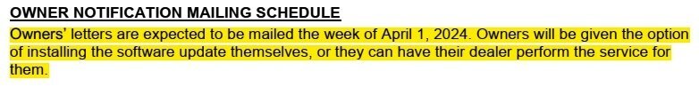
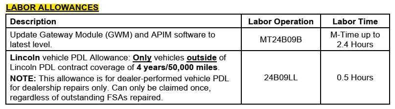
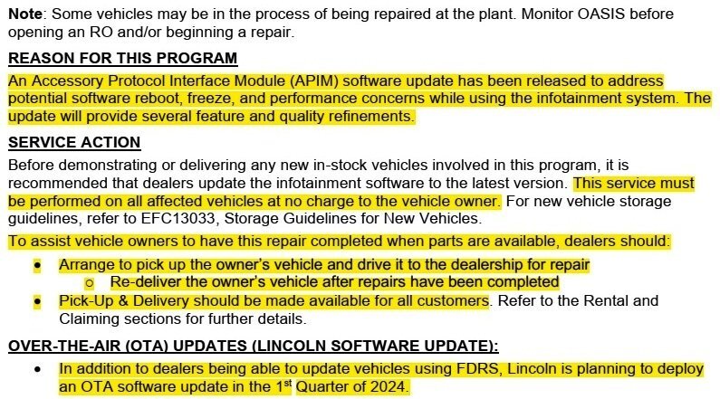
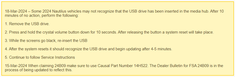
10/02/2024 Edit : This Program has been superceeded by Customer Satisfaction Program 24B54 - Certain 2024 Model Year Nautilus - Update Infotainment Software Customer Satisfaction Program 24B09 - Certain 2024 Nautilus - Update Infotainment Software - Owner Letter.pdf Customer Satisfaction Program 24B09 - Technical Information - Supplement #1.pdf

-
Special Service Message 52347 - 2024 Nautilus - Rear Lamp Condensation
Haz replied to Haz's topic in Recalls, TSBs & Warranty
SSM 52347 2024 Nautilus - Rear Lamp Condensation Some 2024 Nautilus vehicles may exhibit condensation in the rear body mounted or decklid lamp assemblies that does not affect the function of the lamp. This condensation may be due to extended overseas shipping in a high humidity environment and will clear on its own with no service necessary in most cases. A thin film of mist that forms and covers less than 50% of the inside of the lamp that clears is normal and may take as long as 48 hours to dissipate in dry weather conditions. Circular droplets that may appear but do not form a vertical drip are also normal and may take up to 1 week in dry weather conditions to fully dissipate. Condensation that does not clear after 1 week in dry weather conditions or that forms drip marks, streaks or a water puddle inside the lens is not normal and should be resolved with lamp replacement as necessary. Refer to Workshop Manual, Section 417-01 if lamp replacement is necessary.- 1 reply
-
- 1
-

-
2018 Edge 110v inverter not working
Haz replied to fletch8527's topic in Accessories & Modifications
Welcome to the Forum, @fletch8527 ! From the 2018 Edge Workshop Manual... (Placing device cursor over underlined acronyms may yield full-words descriptions) Direct Current/Alternating Current (DC/AC) Inverter - System Operation and Component Description System Diagram System Operation Network Message Chart Broadcast Message Originating Module Message Purpose Power pack torque status PCM Used to determine if the engine is started. A/C OUTLETS (POWER POINTS) This vehicle is equipped with a 110v A/C outlet on the center floor console. The AC outlet is equipped with an amber LED that indicates the system status. The LED is illuminated continuously when the inverter is ON and the system is operating normally. If the LED has a series of three flashes, the power point is overloaded. The LED flashes constantly if the ignition is on and a fault is detected. DC/AC INVERTER The direct current/alternating current (DC/AC) inverter converts 12 volts DC to 110 volts AC to power AC devices rated 150 watts or less. The 110 volts AC created by the inverter measures differently than conventional, utility generated AC with some multi-meters. SYSTEM OPERATION When the ignition is turned to RUN and the engine started, the LED will flash as the inverter runs a self-test. The LED will then illuminate constantly and the inverter supplies 110 volts to the AC outlet. The driver door should be closed and engine must be started for the AC outlet to begin to operate. In accessory delay mode, the direct current/alternating current (DC/AC) inverter shuts off after 13 minutes. When the direct current/alternating current (DC/AC) inverter stops receiving information from the BCM over the LIN circuit indicating the engine is started, it begins counting the elapsed time. After 13 minutes the direct current/alternating current (DC/AC) inverter shuts down. Cycling the ignition from RUN to OFF and back to RUN will reset the timer is and the inverter is powered back on by but only for another 13 minutes. This prevents the 12-volt battery from being fully discharged. If the vehicle is started, the inverter operation is not time-limited. The direct current/alternating current (DC/AC) inverter has a self-protection feature for the following conditions: Short circuits on the inverter output circuits: The inverter shuts down if it detects a short on the output circuit(s). After 6 seconds, it restarts and checks for a short condition. If the condition still exists, the inverter shuts down again. The inverter restarts 5 times and if the short still exists on the 5th restart, the inverter disables AC output and the green LED indicator flashes. Low voltage input: The inverter does not operate when the input voltage is less than 11 volts. High voltage input: The inverter does not operate when the input voltage is greater than 16 volts. Load exceeds 150 watts High temperature: The inverter does not operate if it has overheated or if ambient (cabin) temperatures exceed 75 C (167 F). If the self-protection feature is activated, the LED indicator flashes and the direct current/alternating current (DC/AC) inverter does not provide power output to the AC outlet. If the LED is flashing, the problem must be corrected before direct current/alternating current (DC/AC) inverter operation resumes. Refer to the Owner's Literature for a list of appropriate electrical loads and devices. Component Description COMPONENT OPERATION The AC power outlet and inverter module are replaced as separate components. The AC outlets are standard 3-prong outlets, similar to a standard wall outlet. The contacts of the outlet exert a more powerful grip on the plug so that it does not shake loose on poor road surfaces. Document download links> Direct Current-Alternating Current (DC-AC) Inverter - Diagnosis and Testing - 2018 Edge Workshop Manual.pdfDIRECT CURRENT-ALTERNATING CURRENT (DC-AC) INVERTER - Connector C3501 Details - 2018 Edge.pdfDIRECT CURRENT-ALTERNATING CURRENT (DC-AC) INVERTER - Connector C3501 Location - 2018 Edge.pdfALTERNATING CURRENT (AC) POWER OUTLET SOCKET - Connector C3429 Details - 2018 Edge.pdfALTERNATING CURRENT (AC) POWER OUTLET SOCKET - Connector C3429 Location - 2018 Edge.pdfPin Identification Diagram for Diagnosis and Testing Pinpoint Test Step A9 CHECK AC (ALTERNATING CURRENT) OUTLET FOR AN OPEN - 2018 Edge.pdfDirect Current-Alternating Current (DC-AC) Inverter - Removal and Installation - 2018 Edge Workshop Manual.pdf BODY CONTROL MODULE (BCM) - Connector C2280D Details - 2018 Edge.pdf BODY CONTROL MODULE (BCM) - Connector C2280D Location - 2018 Edge.pdf BODY CONTROL MODULE (BCM) - Connector C2280D Location on BCM - 2018 Edge.pdf Alternating Current (AC) Power Outlet Socket - Removal and Installation - 2018 Edge Workshop Manual.pdf Power Inverter Wiring Diagram - 2018 Edge.pdf Direct Current-Alternating Current (DC-AC) Inverter - Description and Operation - 2018 Edge Workshop Manual.pdf Direct Current-Alternating Current (DC-AC) Inverter - Component Location - 2018 Edge Workshop Manual.pdf Good luck!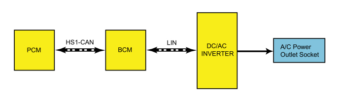
Inverter-ComponentLocationsIllustration.thumb.jpg.c88fcba964ee3b71cdef0bfbb8cea3c3.jpg)

-
I prefer to think of it as us being renewed. Good luck!
-
Welcome to the Forum, @garycrist ! Like your wife's handsome Edge ST, Forum members here will certainly benefit from your professional experience. Good luck!
-
Battery Replacement - BMS reset procedure 15-22
Haz replied to TourGuide's topic in 2015+ Edge & MKX Generation II
The Fusion and Edge Workshop Manual sections on vehicle Charging System are identical, including the Battery Monitoring System reset procedure... Battery Replacement If the vehicle battery is replaced, it is very important to perform the battery monitoring system reset using the scan tool. If the battery monitoring system reset is not carried out, it holds the old battery parameters and time in service counter in memory. Additionally it tells the system the battery is in an aged state and the may limit the Electrical Energy Management system functions. Additional detail is offered in this statement... This reset is reserved only for new battery installation. This reset will clear the learned battery data, the battery time in service, and will affect the aging algorithm parameters, which have been learned since the installation of the battery. Document download links> Charging System - 2.0L EcoBoost - System Operation and Component Description - Edge Workshop Manual.pdf Charging System - 2.7L EcoBoost - System Operation and Component Description - Edge Workshop Manual.pdf Battery Load Shed - Description and Operation - Edge Workshop Manual.pdf Good luck! -
Replacing the Ford EDGE instrument panel
Haz replied to Yurez's topic in Accessories & Modifications
According to the CyanLabs Ford/Lincoln As-Built Module Configuration Database, you'll need to use Forscan to modify the Instrument Panel Control Module (IPC) Line 720-02-02 to Power Liftgate Control (PLC) Disabled and Power Liftgate Chime (LC) Non-DNA. Those two desired programming states are established in concert with programming for Passive Entry Passive Start (PEPS) and ParkAid Switch (PS), with the four potential Power Liftgate Control (PLC) Disable and Power Liftgate Chime (LC) Non-DNA combination-value lines highlighted in the following table... As-Built Programming Location 720-02-02: x⭐xx-xxxx ⭐Values 0=PEPS Disabled, PLC Disabled, PS Disabled, LC Non-DNA 1=PEPS Disabled, PLC Disabled, PS Disabled, LC DNA 2=PEPS Disabled, PLC Disabled, PS Enabled, LC Non-DNA 3=PEPS Disabled, PLC Disabled, PS Disabled, LC DNA 4=PEPS Disabled, PLC Enabled, PS Disabled, LC Non-DNA 5=PEPS Disabled, PLC Enabled, PS Disabled, LC DNA 6=PEPS Disabled, PLC Enabled, PS Enabled, LC Non-DNA 7=PEPS Disabled, PLC Enabled, PS Enabled, LC DNA 8=PEPS Enabled, PLC Disabled, PS Disabled, LC Non-DNA 9=PEPS Enabled, PLC Disabled, PS Disabled, LC DNA A=PEPS Enabled, PLC Disabled, PS Enabled, LC Non-DNA B=PEPS Enabled, PLC Disabled, PS Disabled, LC DNA C=PEPS Enabled, PLC Enabled, PS Disabled, LC Non-DNA D=PEPS Enabled, PLC Disabled, PS Disabled, LC DNA E=PEPS Enabled, PLC Enabled, PS Enabled, LC Non-DNA F=PEPS Enabled, PLC Enabled, PS Enabled, LC DNA As a real-world survey of these data points, I pulled As-Built files for a 2020 Edge SEL without Power Liftgate, and for a 2020 Edge Titanium with Power Liftgate, which as expected, are not identical in the above-described data position... Good luck!versusTitanium(DarkGreenText).jpg.25f171b7bc30f3640fc44eba907523cc.jpg)
-
SSM 52345 - 2022-2024 Various Vehicles - SYNC4 - Error Message When Trying To Enroll In Connected Services Some 2022-2024 various Ford/Lincoln vehicles equipped with SYNC 4 may experience concern where customers are receiving an error message when trying to enroll in connected services. This may be due to the gateway module (GWM) software. To correct the concern, download and run the Transport and Factory Mode Deactivation app: under HS1 modules select BCM > Transport and Factory Mode > Download > Run. When the pop-up message appears for Change Vehicle Mode - Transport/Factory/Normal Mode, press OK. This will proceed to the Transport and Factory Mode Deactivation screen, select Unlock Vehicle Connectivity Settings (21 MY + Vehicles). A pop-up message appears noting Vehicle Is Now In Normal Mode, select OK. This will return to the Transport and Factory Mode Deactivation screen, select Exit. A final pop-up notification stating that the application is finished, select OK. For claiming, use causal part 14G490 and applicable labor operations in Section 10 of the Service Labor Time Standards (SLTS) Manual.
-
The hood bouncing symptom generated much beneficial discussion in Hood Rattle on Highway, originated by @SmittyST. Forum member @omar302 discovered Special Service Message 49931, issued by Ford to dealership Service personnel on July 5, 2021... SSM 49931 2015-2021 Edge, 2016-2018 MKX, 2019-2021 Nautilus - Hood Bounce Or Flutter At High Speeds Some 2015-2021 Edge, 2016-2018 MKX and 2019-2021 Nautilus vehicles may exhibit a hood bounce or flutter condition at high speeds. This may be due to an incorrect adjustment of the rubber bump stops. To correct this condition, make sure the rubber bump stops are in contact with the inner hood sheet metal. Using a piece of paper between the hood and the rubber hood stop, make sure the paper fits snug with hood closed. For claiming, use causal part number 16612 and applicable labor times from Section 12 of the Service Labor Times Standard (SLTS) Manual. Per Special Service Message 49931's advice, try placing a strip of paper across each hood bump stop, leading each paper strip forward, to where you can pull on the paper once the hood is fully latched, just to ensure the hood is bearing load upon both bump stops. Good luck!
-
vent removal inner left side vent removal
Haz replied to Edgelover2017's topic in Interior, A.C., Heat, Interior Trim
Document download link> Center Registers - Removal and Installation - Climate Control System - 2017 Edge Workshop Manual.pdf Good luck!- 3 replies
-
- 2
-
-
- inner left
- center console
- (and 1 more)
-
SSM 52335 2015-2024 Various Vehicles - Oil Leak - Turbocharger Oil Feed And Drain Tube Replacement For 2015-2024 Ford and Lincoln vehicles equipped with turbocharged engines and customer concern of an engine oil leak, refer to Workshop Manual (WSM), Section 303-00 for oil leak inspection and testing methods. Ford has evaluated turbochargers replaced for oil leak symptoms and although oil may collect on the external surface of a turbocharger, it is extremely rare for a turbocharger assembly to be the root cause of the oil leak. Careful inspection of the turbocharger oil feed and drain tubes should be performed along with the recommended WSM procedures as needed. Warranty claims for turbocharger replacement going forward will be assessed. For more information, see General Service Bulletin 24-7022 - Various Vehicles - Diagnosing Turbocharger Oil And Coolant Leaks
-
Do 2011 tail lights fit a 2010
Haz replied to Hodgie's topic in Glass, Lenses, Lighting, Mirrors, Sunroof (BAMR), Wipers
I have no direct experience with them, but perhaps you could use an aftermarket 2-to-3 tail light adapter module, like those used in Recreational Vehicle (RV) applications. For example -- this adapter, or this adapter, or this adapter. Good luck! -
From the 2024 Edge Workshop Manual... Document download links> Transmission Description - Overview - 8F57 (8-Speed & 7-Speed) - 2024 Edge Workshop Manual.pdf Power Transfer Unit - 2.7 EcoBoost - 2024 Edge Workshop Manual.pdf Engine Overview - 2.7 EcoBoost - 2024 Edge Workshop Manual.pdf Oil Pump - Removal and Installation - 2.7 EcoBoost - 2024 Edge Workshop Manual.pdf Good luck! Weblink to...

-
Horizontal headlight adjustment
Haz replied to fishx65's topic in Glass, Lenses, Lighting, Mirrors, Sunroof (BAMR), Wipers
From the 2011 Edge Workshop Manual... Headlamp Assembly - Removal and Installation (Enhanced Image) Bumper Cover - Front - Exploded View (Enhanced Image) Document download links> Headlamp Assembly - Removal and Installation - 2011 Edge Workshop Manual.pdf Headlamp Assembly - Removal and Installation - ENHANCED IMAGE - 2011 Edge Workshop Manual.pdf Bumper Cover - Front - Removal and Installation - 2011 Edge Workshop Manual.pdf Bumper Cover - Front - Exploded View - 2011 Edge Workshop Manual.pdf Bumper Cover - Front - Exploded View - ENANCED IMAGE - 2011 Edge Workshop Manual.pdf Good luck!


- 1 reply
-
- 1
-


Inverter-ComponentLocationsIllustration.jpg.12d17b42629bcca0f69f66d8dec92bc6.jpg)