

Haz
-
Posts
1,251 -
Joined
-
Last visited
-
Days Won
325
Content Type
Profiles
Forums
Gallery
Everything posted by Haz
-
Power Folding Mirror Synchronization Video #2 Power Folding Mirror Synchronization Video #2.mp4
- 1 reply
-
- 1
-

-
Special Service Message 51937 - Various 2015-2023 Vehicles - Inoperative Or Clicking Sound From Power Folding Exterior Mirrors Some vehicles equipped with power folding mirrors may exhibit power folding mirrors that are inoperative or exhibit a clicking sound. This may be due to the mirrors being manually folded in, during transportation, going through a car wash, bumped in a parking lot, or found during pre-delivery inspection (PDI). Prior to the replacement of any components, attempt to synchronize the mirrors by following the Power Mirrors Synchronization procedure. Refer to Workshop Manual (WSM)Section 501-09 Rear View Mirrors - General Procedures - Power Mirrors Synchronization. Power Folding Mirror Synchronization Video #1 Power Folding Mirror Synchronization Video #1.mp4
- 1 reply
-
- 1
-
-
Windshield wiper fluid reveresed
Haz replied to BmbSqd's topic in Glass, Lenses, Lighting, Mirrors, Sunroof (BAMR), Wipers
Additional document download links> WINDSHIELD WASHER PUMP - Wiring Diagram - 2019 Edge.pdf Rear Window Wiper Motor - Wiring Diagram - 2019 Edge.pdf Windshield Wiper Motors - Wiring Diagram - 2019 Edge.pdf Wiper Motors & Washer Pump - Power Distribution Wiring Diagram - 2019 Edge.pdf WINDSHIELD WASHER PUMP - Connector C137 Details - 2019 Edge.pdf WINDSHIELD WASHER PUMP - Connector C137 Location - 2019 Edge.pdf WINDSHIELD WIPER MOTOR LH - Connector C1665 Details - 2019 Edge.pdf Windshield Wiper Motor - Removal and Installation - 2019 Edge Workshop Manual.pdf Cowl Panel - Removal and Installation - 2019 Edge Workshop Manual.pdf Cowl Panel Grille - Removal and Installation - 2019 Edge Workshop Manual.pdf Windshield Wiper Pivot Arm - Removal and Installation - 2019 Edge Workshop Manual.pdf BATTERY JUNCTION BOX (BJB) - Connector C1035B Details - 2019 Edge.pdf BATTERY JUNCTION BOX (BJB) - Connector C1035B Location - 2019 Edge.pdf BATTERY JUNCTION BOX (BJB) Illustration- Shows Connector C1035B Receptacle Location - 2019 Edge.pdf Link to this FordParts web page Titanium Plus packaged Edges with the front camera washer use the following washer pump... Link to this FordParts web page The above FordParts web pages include numerous photos of the described washer pumps. Good luck!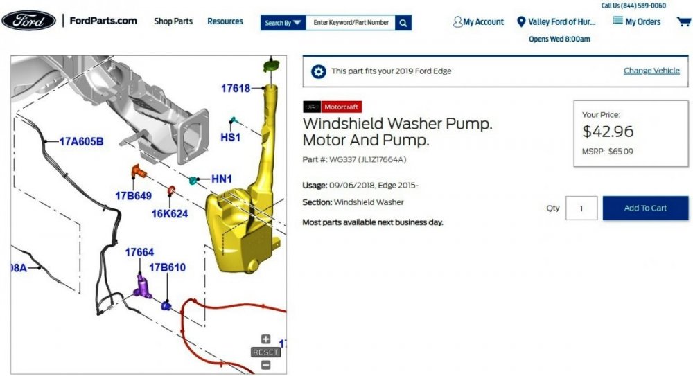
-FordParts.thumb.jpg.ca3dff6490d4e487e562c4dbd06a216a.jpg)
- 2 replies
-
- 1
-
-
- fluid
- windshield
- (and 1 more)
-
Windshield wiper fluid reveresed
Haz replied to BmbSqd's topic in Glass, Lenses, Lighting, Mirrors, Sunroof (BAMR), Wipers
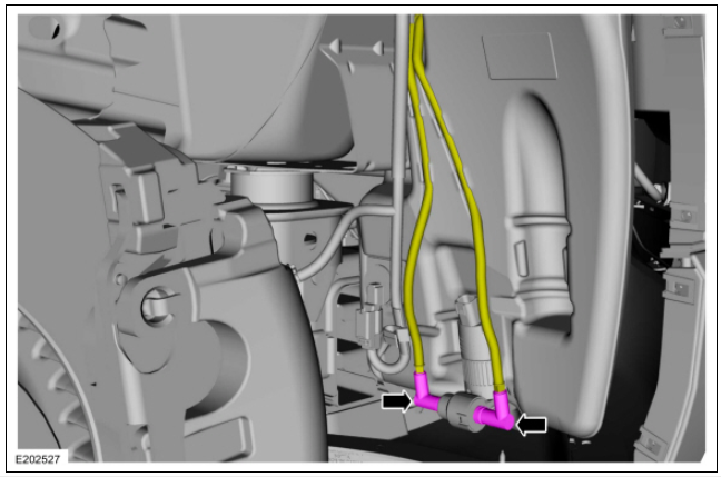
Welcome to the Forum, BmbSqd ! Your Edge's washer pump is attached to the lower portion of the washer fluid reservoir in the forward passenger side corner of the engine compartment... ghlighted You'll notice the two yellow-highlighted washer fluid hoses with their pink-highlighted couplings attached to the washer pump outlets. I expect one hose supplies the windshield nozzles and the other hose supplies the rear window nozzle, per these technical descriptions of front & rear washer operation from the 2019 Edge Workshop Manual... Windshield Washer When the wiper/washer switch is activated, the SCCM sends the washer request to the driver side windshield wiper motor assembly over the LIN . The windshield wash relay is internal to the driver side windshield wiper motor assembly. When the driver side windshield wiper motor assembly activates the internal windshield wash relay, voltage is provided to the washer pump, directing washer fluid to the windshield. If equipped with a front camera, washer solvent is also directed to the front camera lens when the washer pump is active. When the switch is released, the windshield wiper motors will continue to activate for 3 additional wipes and then turn off. Ground for the washer pump is provided through the rear window washer relay located within the BJB . Rear Window Washer When the rear window washer switch is activated, the SCCM sends the request to the driver side windshield wiper motor assembly through the LIN . The driver side windshield wiper motor assembly energizes the rear washer relay (located in the BJB ) and activates the rear window wiper motor. When the driver side windshield wiper motor assembly activates the rear window wash relay, voltage is provided to the washer pump, directing washer fluid to the rear window. When the switch is released, the rear window wiper motor continues to operate for 3 additional wipes and then turns off. Ground for the washer pump is provided through the windshield washer relay within the driver side windshield wiper motor assembly. Presuming the washer fluid hose couplings are not fool-proofed to only connect to the appropriate washer pump outlet for front or rear nozzle, then your swapping the hoses side-to-side may correct your Edge wrong-way spraying issue. Given that you've recently purchased the Edge, it seems unlikely a non-working washer pump was replaced and the wrong-way spray issue went unnoticed, though maybe it was a hurried job. It may be the result of a washer pump malfunction or a wiring/switch issue, but if swapping the hoses produces interim improvement, then it's worth a try. I've pulled relevant sections from the 2019 Edge Workshop and Wiring manuals, which will likely require two posts to provide due to Forum attachment size limitations. Document download links> Wipers and Washers - System Operation and Component Description - 2019 Edge Workshop Manual.pdf Windshield Washer Pump - Removal and Installation - 2019 Edge Workshop Manual.pdf Fender Splash Shield - Removal and Installation - 2019 Edge Workshop Manual.pdf Washer Hose Coupling - General Procedures - 2019 Edge Workshop Manual.pdf Windshield Washer Reservoir - Removal and Installation - 2019 Edge Workshop Manual.pdf Wipers and Washers - Diagnosis and Testing - 2019 Edge Workshop Manual.pdf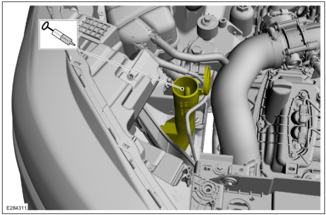
- 2 replies
-
- 1
-
-
- fluid
- windshield
- (and 1 more)
-
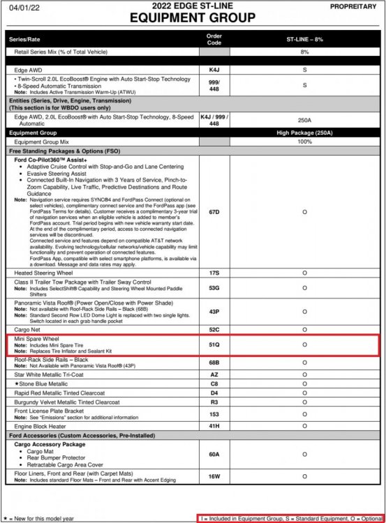
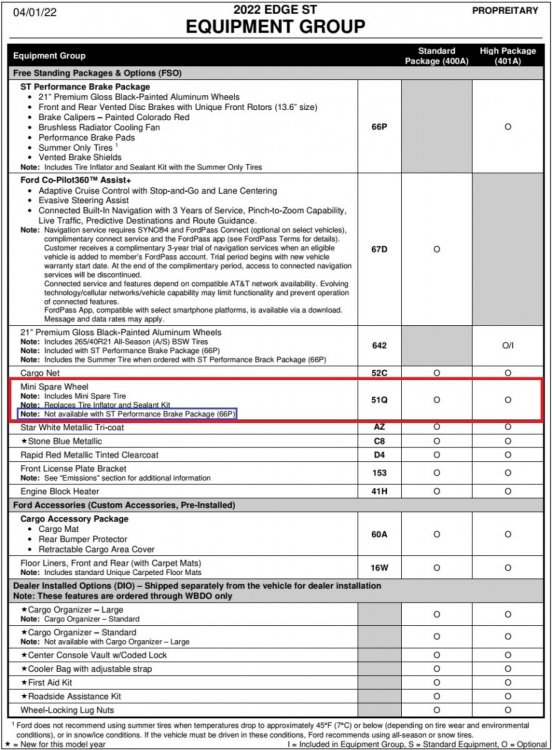
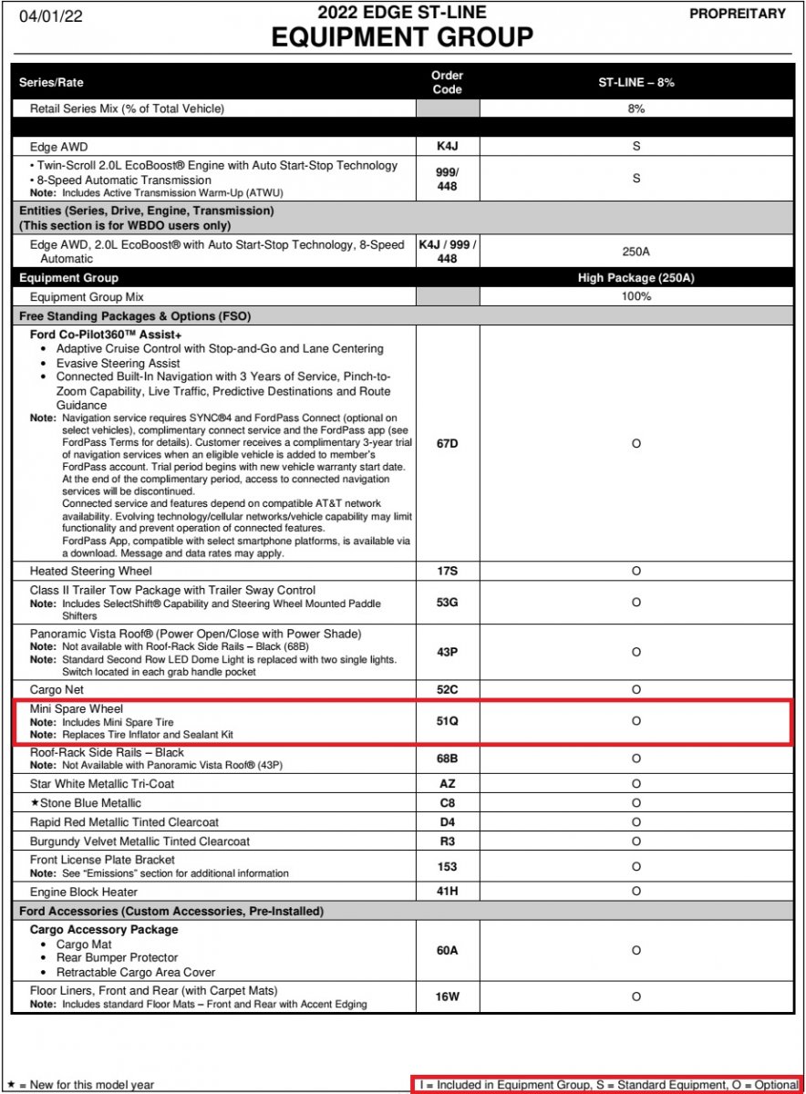
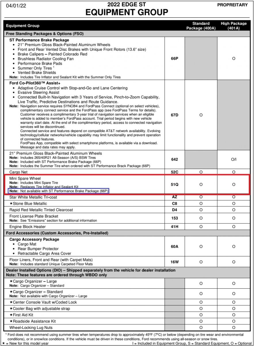
Welcome to the Forum, Gunner3.5 ! The 2022 Edge Order Guide shows the Mini Spare as optional equipment on the ST-Line... ...The Order Guide also shows the Mini Spare as optional on ST, but as Davidoo states, unavailable with the ST Performance Brake Package... Good luck!
-
Splash shield for 2.0 interchangeable with 3.5L?
Haz replied to Oranga's topic in Brakes, Chassis & Suspension
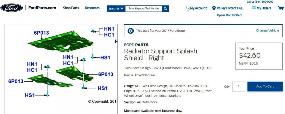
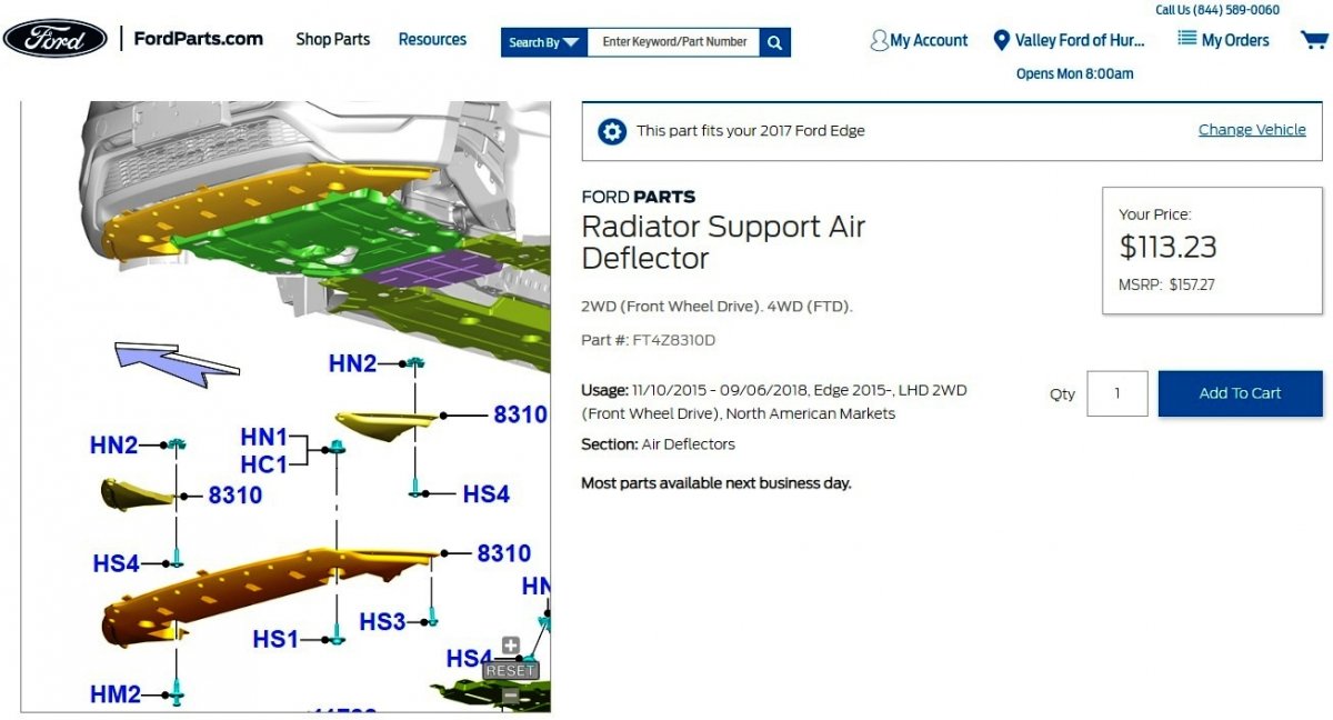
Ford's online parts-selling site shows a 2-piece design Splash Shield for the 2017 3.5L Edge... Link to this web page Link to this web page ...Unless it is the Front Air Deflector you are seeking... Link to this web page The above-linked FordParts web pages include multiple photos of each described part. Good luck!


-
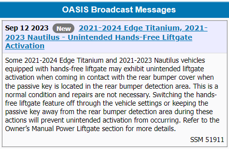
Ford is restating to the Service community that unintended hands-free liftgate operation is normal and no repair is needed to eliminate it, but that the solution for affected vehicle owners is deactivating the power liftgate or not having the passive key fob near the rear bumper when active in the cargo load space ... Good luck!
-
Omar: Yes, the procedure mentions scan-tool usage... Front Toe Adjustment - Vehicles With Active Steering - 2016 Edge Workshop Manual.pdf This causes me to wonder if the scan tool is being used to engage the Active Steering Wheel Lock to ensure the Steering Wheel is secured pointing straight ahead when the Front Toe Adjustment is made. A bit later today, I'll pull all the diagnostic Pinpoint Tests and edit into this post the full library of 2016 Edge Active Steering references. Good luck!
-
Document download links> Information and Entertainment System - Description and Operation- 2008 Edge-MKX Workshop Manual.pdf Module Configuration - Diagnosis and Testing - 2008 Edge-MKX Workshop Manual.pdf Audio Unit Part Number Retrieval - 2008 Edge-MKX Workshop Manual.pdf Instrument Panel Center Finish Panel - Removal and Installation - 2008 Edge-MKX Workshop Manual.pdf Instrument Panel Speaker - Removal and Installation - 2008 Edge-MKX Workshop Manual.pdf Audio Control Module (ACM) - Removal and Installation - 2008 Edge-MKX Workshop Manual.pdf Audio Control Module (ACM) - R & I Enhanced Image - 2008 Edge-MKX Workshop Manual.pdf Global Positioning System (GPS) Antenna - Removal and Installation - 2008 Edge-MKX Workshop Manual.pdf Audio System-Navigation - Wiring Diagram - 2008 Edge.pdf AUDIO CONTROL MODULE (ACM) - Connector C240A Details - 2008 Edge-MKX.pdf AUDIO CONTROL MODULE (ACM) - Connector C240B Details - 2008 Edge-MKX.pdf AUDIO CONTROL MODULE (ACM) - Connector C240C Details - 2008 Edge-MKX.pdf AUDIO CONTROL MODULE (ACM) - Connectors C240A, C240B, C240C Location - 2008 Edge-MKX.pdf Steering Wheel Controls - With SYNC & Navigation - Wiring Diagram - 2008 Edge-MKX.pdf Good luck!
-
Document download link> 2008 Pioneer Navigation System Supplement.pdf Good luck!

-
2011 Edge Cooling Fans not running
Haz replied to atrdriver's topic in Interior, A.C., Heat, Interior Trim
Multi-model diagnostic procedure and Edge-specific supporting documents to address your Edge's cooling fan issue... Document download links> Pinpoint Test KN - Variable Speed Electric Cooling Fan - Powertrain Control-Emissions Diagnosis Manual.pdf COOLING FAN MODULE - Without Trailer Tow - Wiring Diagram - 2011 Edge Workshop Manual.pdf COOLING FAN MODULE - With Trailer Tow - Wiring Diagram - 2011 Edge Workshop Manual.pdf Battery Junction Box (BJB) - Illustration - 2011 Edge.pdf Battery Junction Box (BJB) - Fuse & Relay Listing - 2011 Edge.pdf POWERTRAIN CONTROL MODULE (PCM) - Connector C175B Details - 2011 Edge.pdf POWERTRAIN CONTROL MODULE (PCM) - Connector C175B Location - 2011 Edge.pdf COOLING FAN MODULE - Connector C1554 Details - 2011 Edge.pdf COOLING FAN MODULE - Connector C1554 Location - 2011 Edge Workshop Manual.pdf POWERTRAIN CONTROL MODULE (PCM) - Connector C175B Location - 2011 Edge.pdf Air Cleaner - Removal and Installation - 2011 Edge Workshop Manual.pdf Intake Air System Components - Exploded View Enhanced Image - 2011 Edge-MKX Workshop Manual.pdf Intake Air System Components - Exploded View - 2011 Edge-MKX Workshop Manual.pdf Cooling Fan and Shroud - Removal and Installation - 2011 Edge Workshop Manual.pdf Cooling Fan and Shroud - R&I Enhanced Image - 2011 Edge Workshop Manual.pdf Cooling Fan and Shroud - R&I Enhanced Connectors Illustration - 2011 Edge Workshop Manual.pdf Good luck! -
Good luck!
-
Welcome to the Forum, Remis ! Diagnostic information from the 2015 Edge Workshop Manual... The Manual Liftgate Latch Release Is Inoperative Normal Operations and Fault Conditions Liftgate Latch Release (manual liftgate) The liftgate latch can be released using: the exterior liftgate release switch. a valid programmed passive key. The BCM sends a voltage signal to the exterior liftgate release switch. When the liftgate release switch is pressed, the voltage signal is routed to ground, indicating a request to release the liftgate latch. The BCM momentarily provides voltage to the liftgate latch to actuate the release motor. When using the liftgate release switch, the BCM releases the liftgate only when the doors have been electronically unlocked and the vehicle is in PARK. When using a programmed RKE transmitter, press the liftgate release button twice within 3 seconds to release the liftgate latch. The liftgate latch releases if the vehicle speed is 5 km/h (3.1 mph) or less. The liftgate latch can also be released using the passive entry feature. Refer to Liftgate Passive Entry in this section. Passive Entry (if equipped) NOTE: To perform an accurate diagnosis of a concern, make sure the vehicle has a fully charged 12V battery and is in good condition when performing any electrical pinpoint tests. When the vehicle’s 12-volt battery is below a set threshold, certain features can be limited or become inoperative and lead to misdiagnosis. NOTE: Some models are not equipped with the passive entry feature, but are equipped with push button start. The passive entry feature unlocks or locks the doors or opens the liftgate without having to use a mechanical key blade or the RKE transmitter feature. When the BCM detects a lock or unlock sensor is touched on an exterior door handle, or the exterior liftgate release button is pressed, it activates the low frequency antenna in the corresponding exterior door handle or inside the luggage compartment area. The low frequency antenna sends out a signal to activate the passive key. The passive key then responds by sending a high frequency signal back to the RTM . The RTM interprets the high frequency signal from the passive key and sends the information to the BCM . If the BCM detects a valid programmed passive key, the BCM unlocks the driver door, unlocks or locks all 4 doors, releases the liftgate latch (manual liftgate) or sends a command to the RGTM to power open the liftgate (power liftgate). The passive entry (Intelligent Access) feature is part of vehicle load shed strategy. BCM DTC Fault Trigger Conditions DTC Description Fault Trigger Conditions B1219:11 Interior Boot/Trunk Release Switch: Circuit Short To Ground Sets when the BCM detects a short to ground from the exterior liftgate release switch input circuit. B12EE:11 Liftgate/Tailgate/Trunk Release: Circuit Short To Ground Sets when the BCM detects a short to ground from the liftgate latch release output circuit. B12EE:15 Liftgate/Tailgate/Trunk Release: Circuit Short To Battery or Open Sets when the BCM detects an open from the liftgate latch release output circuit. If the liftgate latch release is inoperative, GO to Pinpoint Test N If the liftgate does not latch, DISCONNECT the liftgate latch electrical connector and CHECK the operation of the latch using a screwdriver. If the latch does not fully latch (2 clicks), INSTALL a new liftgate latch. If the latch fully latches (2 clicks), REFER to the Wiring Diagrams manual to identify the possible cause of the circuit short in the liftgate latch release circuit. Possible Causes Wiring, terminals or connectors Liftgate release switch Liftgate latch BCM Visual Inspection and Diagnostic Pre-checks Inspect the liftgate release switch for damage. PINPOINT TEST N: THE MANUAL LIFTGATE LATCH RELEASE IS INOPERATIVE NOTE: This pinpoint test does not diagnose liftgate release concerns for vehicles with the power liftgate feature. Refer to Section 501-03 for power liftgate diagnostics. N1 CHECK THE LIFTGATE RELEASE INPUT FOR A SHORT TO GROUND USING THE BCM (BODY CONTROL MODULE) LIFTGATE RELEASE SWITCH STATUS (LFTGATE_R_SW) PID (PARAMETER IDENTIFICATION) Ignition ON. Using a diagnostic scan tool, view the BCM Parameter Identifications (PIDs). Using a diagnostic scan tool, view the BCM PID LFTGATE_R_SW. Does the PID indicate the liftgate release switch is continuously pressed? Yes GO to N2 No GO to N4 N2 CHECK THE LIFTGATE RELEASE SWITCH USING THE BCM (BODY CONTROL MODULE) LIFTGATE RELEASE SWITCH STATUS (LFTGATE_R_SW) PID (PARAMETER IDENTIFICATION) Ignition OFF. Disconnect Liftgate Release Switch C4216. Ignition ON. Using a diagnostic scan tool, view the BCM PID LFTGATE_R_SW. Does the PID continue to indicate the switch is pressed? Yes GO to N3 No INSTALL a new liftgate release switch. REFER to: Liftgate Release Switch (501-14 Handles, Locks, Latches and Entry Systems, Removal and Installation). N3 CHECK THE LIFTGATE RELEASE SWITCH INPUT CIRCUIT FOR A SHORT TO GROUND Ignition OFF. Disconnect BCM C2280D. Measure: Positive Lead Measurement / Action Negative Lead C4216 Pin 1 Ground Is the resistance greater than 10,000 ohms? Yes GO to N12 No REPAIR the circuit. N4 CHECK THE BCM (BODY CONTROL MODULE) LIFTGATE RELEASE SWITCH STATUS (LFTGATE_R_SW) PID (PARAMETER IDENTIFICATION) Using a diagnostic scan tool, view the BCM LFTGATE_R_SW PID while pressing the liftgate release switch. Does the PID indicate the switch is pressed? Yes GO to N8 No GO to N5 N5 BYPASS THE LIFTGATE RELEASE SWITCH WHILE MONITORING THE BCM (BODY CONTROL MODULE) LIFTGATE RELEASE SWITCH STATUS (LFTGATE_R_SW) PID (PARAMETER IDENTIFICATION) Ignition OFF. Disconnect Liftgate Release Switch. Ignition ON. Connect: Lead 1 Measurement / Action Lead 2 C4216 Pin 1 C4216 Pin 2 Using a diagnostic scan tool, view the BCM LFTGATE_R_SW PID . Does the PID indicate the switch is pressed? Yes REMOVE the fused jumper wire. INSTALL a new liftgate release switch. REFER to: Liftgate Release Switch (501-14 Handles, Locks, Latches and Entry Systems, Removal and Installation). No REMOVE the fused jumper wire. GO to N6 N6 CHECK THE LIFTGATE RELEASE SWITCH GROUND CIRCUIT FOR AN OPEN WHILE MONITORING THE BCM (BODY CONTROL MODULE) LIFTGATE RELEASE SWITCH STATUS (LFTGATE_R_SW) PID (PARAMETER IDENTIFICATION) Connect: Lead 1 Measurement / Action Lead 2 C4216 Pin 1 Ground Using a diagnostic scan tool, view the BCM LFTGATE_R_SW PID . Does the PID indicate the switch is pressed? Yes REMOVE the fused jumper wire. REPAIR the circuit. No REMOVE the fused jumper wire. GO to N7 N7 CHECK THE LIFTGATE RELEASE SWITCH INPUT CIRCUIT FOR AN OPEN Ignition OFF. Disconnect BCM C2280D. Measure: Positive Lead Measurement / Action Negative Lead C4216 Pin 1 C2280D Pin 1 Is the resistance less than 3 ohms? Yes GO to N12 No REPAIR the circuit. N8 CHECK FOR VOLTAGE TO THE LIFTGATE LATCH RELEASE MOTOR NOTICE: The following step uses a test lamp to simulate normal circuit loads. Use only a Rotunda Test Lamp (SGT27000) or 250-300mA incandescent bulb test lamp. To avoid connector terminal damage, use the Rotunda Flex Probe kit for the test lamp probe connection to the vehicle. Do not use the test lamp probe directly on any connector. Ignition OFF. Disconnect Liftgate Latch C479. Ignition ON. Using a diagnostic scan tool, carry out the BCM self-test. Connect: Positive Lead Measurement / Action Negative Lead C479 Pin 2 Ground Unlock the doors using a door lock control switch. NOTE: The BCM only supplies voltage to the actuator momentarily. It is important to monitor the test lamp while pressing the liftgate release switch. While pressing the liftgate release switch, monitor the test lamp. Does the test lamp momentarily illuminate? Yes GO to N9 No GO to N10 N9 CHECK THE LIFTGATE LATCH RELEASE MOTOR GROUND CIRCUIT FOR AN OPEN NOTICE: The following step uses a test lamp to simulate normal circuit loads. Use only a Rotunda Test Lamp (SGT27000) or 250-300mA incandescent bulb test lamp. To avoid connector terminal damage, use the Rotunda Flex Probe kit for the test lamp probe connection to the vehicle. Do not use the test lamp probe directly on any connector. Connect: Positive Lead Measurement / Action Negative Lead C479 Pin 2 C479 Pin 5 NOTE: The BCM only supplies voltage to the actuator momentarily. It is important to monitor the test lamp while pressing the liftgate release switch. While pressing the liftgate release switch, monitor the test lamp. Does the test lamp momentarily illuminate? Yes INSTALL a new liftgate latch. REFER to: Liftgate Latch (501-14 Handles, Locks, Latches and Entry Systems, Removal and Installation). No REPAIR the circuit. N10 CHECK THE LIFTGATE LATCH RELEASE MOTOR VOLTAGE SUPPLY CIRCUIT FOR A SHORT TO GROUND Ignition OFF. Disconnect BCM C2280F. Measure: Positive Lead Measurement / Action Negative Lead C479 Pin 2 Ground Is the resistance greater than 10,000 ohms? Yes GO to N11 No REPAIR the circuit. N11 CHECK THE LIFTGATE LATCH RELEASE MOTOR VOLTAGE SUPPLY CIRCUIT FOR AN OPEN Measure: Positive Lead Measurement / Action Negative Lead C479 Pin 2 C2280F Pin 31 Is the resistance less than 3 ohms? Yes GO to N12 No REPAIR the circuit. N12 CHECK FOR CORRECT BCM (BODY CONTROL MODULE) OPERATION Disconnect and inspect all the BCM connectors. Repair: corrosion (install new connectors or terminals - clean module pins) damaged or bent pins - install new terminals pins pushed-out pins - install new pins as necessary Reconnect the BCM connectors and make sure they seat and latch correctly. Operate the system and determine if the concern is still present. Is the concern still present? Yes CHECK OASIS for any applicable Technical Service Bulletins (TSBs). If a TSB exists for this concern, DISCONTINUE this test and FOLLOW TSB instructions. If no Technical Service Bulletins (TSBs) address this concern, VIN required to access Guided Routine (BCM) No The system is operating correctly at this time. The concern may have been caused by module connections. ADDRESS the root cause of any connector or pin issues. Document download links> Liftgate Latch Manual Release - General Procedures - 2015 Edge Workshop Manual.pdf Liftgate Latch - Removal and Installation - 2015 Edge Workshop Manual.pdf LIFTGATE-LUGGAGE COMPARTMENT LID LATCH - Connector C479 Details - 2015 Edge.pdf LIFTGATE-LUGGAGE COMPARTMENT LID LATCH - Connector C479 Location - 2015 Edge.pdf Liftgate Release Switch - Removal and Installation - 2015 Edge Workshop Manual.pdf LIFTGATE RELEASE SWITCH - Connector C4216 Details - 2015 Edge.pdf LIFTGATE RELEASE SWITCH - Connector C4216 Location - 2015 Edge.pdf Liftgate Trim Panel - Removal and Installation - 2015 Edge Workshop Manual.pdf Body Control Module (BCM) - Connectors C2280D & C2280F Attachment Locations on BCM - 2015 Edge.pdf BODY CONTROL MODULE (BCM) - Connector C2280D Details - 2015 Edge.pdf BODY CONTROL MODULE (BCM) - Connector C2280D Location - 2015 Edge.pdf BODY CONTROL MODULE (BCM) - Connector C2280F Details - 2015 Edge.pdf BODY CONTROL MODULE (BCM) - Connector C2280F Location - 2015 Edge.pdf Beyond this Pinpoint Test N diagnostic procedure, I find no Technical Service Bulletin (TSB) addressing the liftgate latching issue you describe. Good luck!
-
P1450 code Purge Valve fixed but code comes back again one month later?
Haz replied to fairlaniac's topic in 2.0L EcoBoost
From the 2017 Ford Powertrain Control/Emissions Diagnosis Manual, a multi-model/multi-engine diagnostic reference... Document download link> PINPOINT TEST HX - EVAPORATIVE EMISSION (EVAP) SYSTEM AND MONITOR.pdf If you progress toward undertaking the many circuit tests in the Pinpoint Test HX diagnostic procedure, I can provide Edge-specific connector details and location illustrations, and wiring diagrams. Good luck!
-
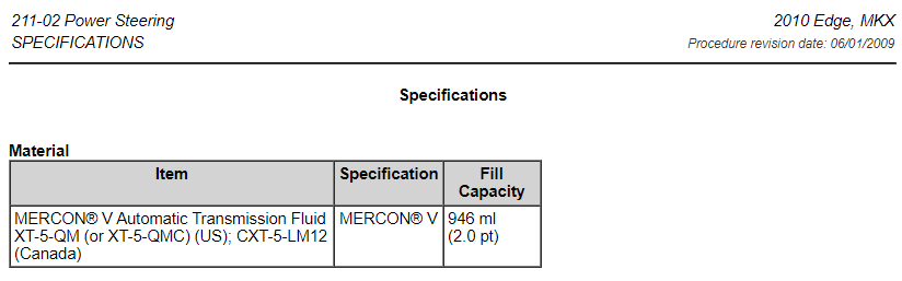
Welcome to the Forum, CEdge2010 ! From the 2010 Edge Workshop Manual... Power Steering Fluid Leak Test NOTE: This test should only be carried out if a leak in the system has not been detected during a thorough visual inspection. Refer to Inspection and Verification in this section. Remove the power steering pump reservoir cap and check the power steering fluid level. If necessary, add the specified power steering fluid. Tightly install the Power Steering Evacuation Cap onto the reservoir and connect the Vacuum Pump Kit to the Evacuation Cap. Using the Vacuum Pump Kit, apply 68-85 kPa (20-25 in-Hg) of vacuum to the power steering system. Observe the vacuum gauge for 30 seconds. If the vacuum gauge reading drops more than 3 kPa (0.88 in-Hg), a leak is present. Remove the Vacuum Pump Kit. Start the engine and insert the Dial Thermometer into the Evacuation Cap. NOTICE: Do not hold the steering wheel at the stops for an extended amount of time. Damage to the power steering pump may occur. With the engine at idle, raise the power steering fluid temperature to 74-80°C (165-176°F) by rotating the steering wheel fully to the left and right several times. Stop the engine and visually inspect the system for leaks. If a leak is evident, repair as necessary. If a leak is not evident, add the specified UV fluorescent tracer dye to the power steering fluid. Use 14.78 ml (1/2 oz) of dye solution for every 1.89L (2 qt) of power steering fluid. Start the engine. NOTICE: Do not hold the steering wheel at the stops for an extended amount of time. Damage to the power steering pump may occur. With the engine at idle, raise the power steering fluid temperature to 74-80°C (165-176°F) by rotating the steering wheel fully to the left and right several times. Stop the engine and inspect the system for traces of UV dye using the 100W/12 Volt DC UV Lamp. Repair as necessary. Document download links> Power Steering System Flushing - General Procedures - 2010 Edge Workshop Manual.pdf Power Steering System Purging - General Procedures - 2010 Edge Workshop Manual.pdf Power Steering System Filling - General Procedures - 2010 Edge Workshop Manual.pdf Good luck!
-
Blend,Mode and Recirculation
Haz replied to 2015Edge2015's topic in Interior, A.C., Heat, Interior Trim
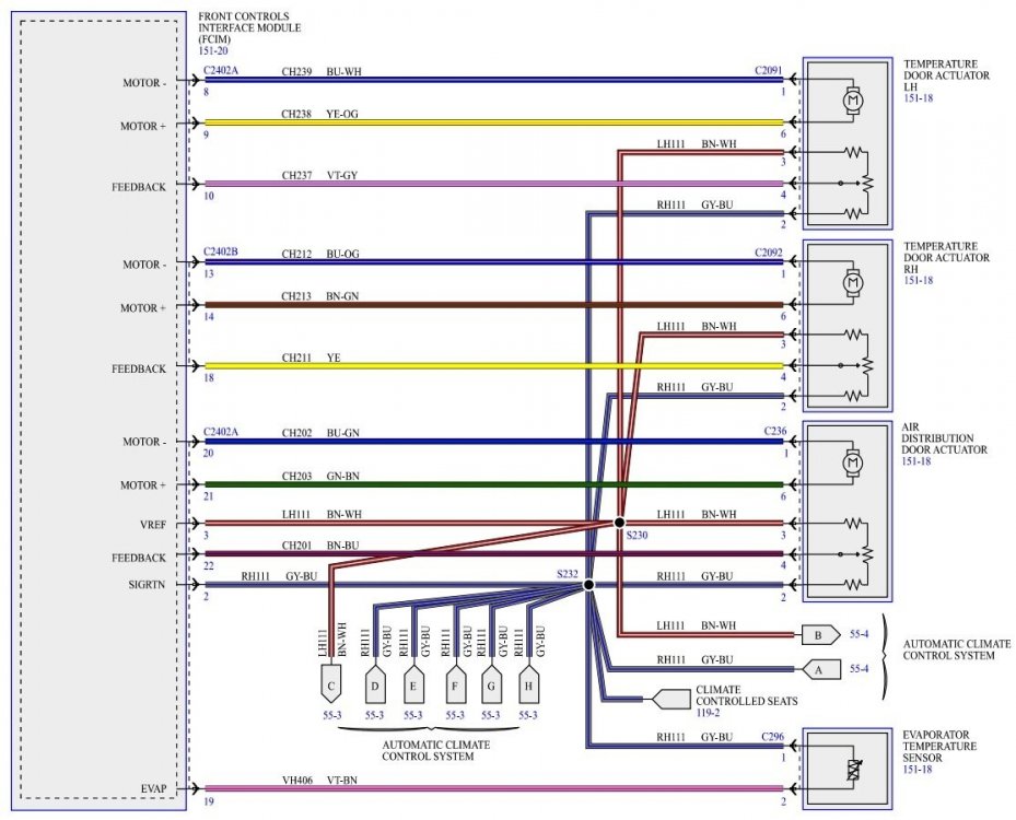
From the 2015 Edge Workshop Manual... Climate Control System - Dual Automatic Temperature Control (DATC) - Component Location Air Handling There are 4 door actuators that control the air flow into the passenger compartment: Air distribution Air inlet Driver side temperature Passenger side temperature All of the door actuators contain a reversible electric motor and a potentiometer. The potentiometer circuit consists of a 5-volt reference signal connected to one end of a variable resistor, and a signal ground connected to the other. A signal circuit is connected to a contact wiper, which is driven along the variable resistor by the actuator shaft. The signal to the FCIM from the contact wiper indicates the position of the actuator door. The FCIM powers the actuator motors to move the doors to the desired positions. The desired door positions are calculated by the FCIM based on the set temperature, in-vehicle temperature, ambient air temperature and sunload. When an airflow mode, desired driver or passenger temperature, fresh air, or recirculation mode is selected, the FCIM moves the actuator motor in the desired direction. The FCIM sends a PWM signal to the blower motor speed control to regulate the blower speed as necessary. The blower motor speed control provides variable ground feed for the blower motor based on the input from the FCIM . A delay function provides a gradual increase or decrease in blower motor speed under all conditions. AUTO When AUTO is selected: the HVAC system operates in a manner to achieve and maintain the temperature set by the operator. the driver and passenger side temperature doors are automatically controlled by the FCIM based on the temperature setting. the A/C compressor is automatically controlled by the PCM from information sent by the FCIM , based on the temperature setting. The A/C compressor operates as long as the outside temperature is above approximately 0°C (32°F). the blower motor speed is automatically controlled through the blower motor speed control that receives a PWM signal from the FCIM based on the temperature setting, but can be manually overridden. the FCIM controls the air inlet door to recirculate, partially recirculate or open to the fresh air position depending on the in-car temperature and humidity sensor inputs. OFF When OFF is selected: the air inlet door closes, preventing outside air and allowing only recirculated air. the blower motor is off. MAX A/C When MAX A/C is selected: the air inlet door closes, preventing outside air and allowing only recirculated air. the recirculated air indicator is illuminated (recirculated air forced on). the footwell vent doors and defrost vent/register doors operate in combination to direct airflow to the instrument panel registers. the temperature doors move to the full cool position. Air temperature can be manually overridden. the A/C button is illuminated. the A/C compressor operates as long as the outside temperature is above approximately 0°C (32°F). the blower motor is commanded to the highest speed. The blower motor speed is adjustable. PANEL When PANEL mode is selected: the recirculated air request button is enabled. If the recirculated air request button is selected (indicator on), the air inlet door closes, preventing outside air from entering the passenger compartment. If the recirculated air request button is not selected (indicator off), the air inlet door opens, allowing only outside air into the passenger compartment. the footwell vent doors and defrost vent/register doors operate in combination to direct airflow to the instrument panel registers. blended air temperature is available. Only when A/C compressor operation has been selected by pressing the A/C button (indicator on) can the airflow temperature be cooled below the outside air temperature. the blower motor is on and the speed is adjustable. PANEL/FLOOR When PANEL/FLOOR mode is selected: the recirculated air request button is enabled. If the recirculated air request button is selected (indicator on), the air inlet door closes, preventing outside air from entering the passenger compartment. If the recirculated air request button is not selected (indicator off), the air inlet door opens, allowing only outside air into the passenger compartment. the air distribution doors operate in combination to direct airflow to the floor duct and the instrument panel registers. A small amount of airflow from the side window demisters and defrost duct is present. blended air temperature is available. Only when A/C compressor operation has been selected by pressing the A/C button (indicator on) can the airflow temperature be cooled below the outside air temperature. the blower motor is on and the speed is adjustable. FLOOR When FLOOR mode is selected: the recirculated air request button is enabled. If the recirculated air request button is selected (indicator on), the air inlet door closes, preventing outside air from entering the passenger compartment. If the recirculated air request button is not selected (indicator off), the air inlet door opens, allowing only outside air into the passenger compartment. the air distribution doors operate in combination to direct airflow to the floor duct. A small amount of airflow from the defroster duct and side window demisters is present. blended air temperature is available. Only when A/C compressor operation has been selected by pressing the A/C button (indicator on) can the airflow temperature be cooled below the outside air temperature. the blower motor is on and the speed is adjustable. FLOOR/DEFROST When FLOOR/DEFROST mode is selected: the recirculated air request button is enabled. If the recirculated air request button is selected (indicator on), the air inlet door closes, preventing outside air from entering the passenger compartment. If the recirculated air request button is not selected (indicator off), the air inlet door opens, allowing only outside air into the passenger compartment. the air distribution doors operate in combination to direct airflow to the floor duct, the defroster duct and the side window demisters. blended air temperature is available. Only when A/C compressor operation has been selected by pressing the A/C button (indicator on) can the airflow temperature be cooled below the outside air temperature. the blower motor is on and the speed is adjustable. MAX DEFROST When MAX DEFROST mode is selected: the recirculated air request button is disabled. The air inlet door opens, allowing only outside air into the passenger compartment. the air distribution doors operate in combination to direct airflow to the defroster duct and side window demisters. A small amount of airflow from the floor duct is present. the A/C is turned on in defrost mode. The A/C compressor operates as long as the outside temperature is above approximately 0°C (32°F). the temperature is set to the highest setting and is not adjustable. the fan is set to the highest speed and is not adjustable. MAX DEFROST can be exited by pressing the AUTO button. Climate Control System - Dual Automatic Temperature Control (DATC) - Front Controls Interface Module (FCIM) to Air Flow Door Actuators - Wiring Diagram Climate Control System - Electronic Manual Temperature Control (EMTC) - Component Location Air Handling There are 3 door actuators that control the air flow into the passenger compartment: Air distribution Air inlet Temperature All of the door actuators contain a reversible electric motor and a potentiometer. The potentiometer circuit consists of a 5-volt reference signal connected to one end of a variable resistor, and a signal ground connected to the other. A signal circuit is connected to a contact wiper, which is driven along the variable resistor by the actuator shaft. The signal to the FCIM from the contact wiper indicates the position of the actuator door. The FCIM powers the actuator motors to move the doors to the desired positions. The desired door positions are calculated by the FCIM based on the set temperature, in-vehicle temperature, ambient air temperature and sunload. When an airflow mode, desired temperature, fresh air, or recirculation mode is selected, the FCIM moves the actuator motor in the desired direction. The FCIM sends a PWM signal to the blower motor speed control to regulate the blower speed as necessary. The blower motor speed control provides variable ground feed for the blower motor based on the input from the FCIM . A delay function provides a gradual increase or decrease in blower motor speed under all conditions. OFF When OFF is selected: the air inlet door closes, preventing outside air and allowing only recirculated air. the blower motor is off. MAX A/C When MAX A/C is selected: the air inlet door closes allowing only recirculated air. the recirculated air indicator is illuminated (recirculated air forced on). the footwell vent doors and defrost vent/register doors operate in combination to direct airflow to the instrument panel registers. the temperature door moves to the full cool position. Air temperature can be manually overridden. the A/C button is illuminated. the A/C compressor operates if the outside temperature is above approximately 0°C (32°F). the blower motor is commanded to the highest speed. The blower motor speed is adjustable. PANEL When PANEL mode is selected: the recirculated air request button is enabled. If the recirculated air request button is selected (indicator on), the air inlet door closes, preventing outside air from entering the passenger compartment. If the recirculated air request button is not selected (indicator off), the air inlet door opens, allowing only outside air into the passenger compartment. the footwell vent doors and defrost vent/register doors operate in combination to direct airflow to the instrument panel registers. blended air temperature is available. The airflow temperature is only cooled below the outside air temperature when the A/C is commanded on. the blower motor is on and the speed is adjustable. PANEL/FLOOR When PANEL/FLOOR mode is selected: the recirculated air request button is enabled. If the recirculated air request button is selected (indicator on), the air inlet door closes, preventing outside air from entering the passenger compartment. If the recirculated air request button is not selected (indicator off), the air inlet door opens, allowing only outside air into the passenger compartment. the air distribution doors operate in combination to direct airflow to the floor duct and the instrument panel registers. A small amount of airflow from the side window demisters and defrost duct is present. blended air temperature is available. The airflow temperature is only cooled below the outside air temperature when the A/C is commanded on. the blower motor is on and the speed is adjustable. FLOOR When FLOOR mode is selected: the recirculated air request button is enabled. If the recirculated air request button is selected (indicator on), the air inlet door closes, preventing outside air from entering the passenger compartment. If the recirculated air request button is not selected (indicator off), the air inlet door opens, allowing only outside air into the passenger compartment. the air distribution doors operate in combination to direct airflow to the floor duct. A small amount of airflow from the defroster duct and side window demisters is present. blended air temperature is available. The airflow temperature is only cooled below the outside air temperature when the A/C is commanded on. the blower motor is on and the speed is adjustable. FLOOR/DEFROST When FLOOR/DEFROST mode is selected: the recirculated air request button is enabled. If the recirculated air request button is selected (indicator on), the air inlet door closes, preventing outside air from entering the passenger compartment. If the recirculated air request button is not selected (indicator off), the air inlet door opens, allowing only outside air into the passenger compartment. the air distribution doors operate in combination to direct airflow to the floor duct, the defroster duct and the side window demisters. blended air temperature is available. The airflow temperature is only cooled below the outside air temperature when the A/C is commanded on. the blower motor is on and the speed is adjustable. MAX DEFROST When MAX DEFROST mode is selected: the recirculated air request button is disabled. The air inlet door opens, allowing only outside air into the passenger compartment. the air distribution doors operate in combination to direct airflow to the defroster duct and side window demisters. A small amount of airflow from the floor duct is present. the A/C is turned on in defrost mode. The A/C compressor operates as long as the outside temperature is above approximately 0°C (32°F). the temperature is set to the highest setting and is not adjustable. the fan is set to the highest speed and is not adjustable. MAX DEFROST can be exited by pressing the AUTO button. Climate Control System - Electronic Manual Temperature Control (EMTC) - Front Controls Interface Module (FCIM) to Air Flow Door Actuators - Wiring Diagram Document download links> Air Distribution Door Actuator - Removal and Installation - 2015 Edge Workshop Manual.pdf Gateway Module A (GWM) - Removal and Installation - 2015 Edge Workshop Manual.pdf Supplemental Restraint System (SRS) Depowering - General Procedures - 2015 Edge Workshop Manual.pdf Driver Knee Airbag - Removal and Installation - 2015 Edge Workshop Manual.pdf Supplemental Restraint System (SRS) Repowering - General Procedures - 2015 Edge Workshop Manual.pdf Air Inlet Door Actuator - Removal and Installation - 2015 Edge Workshop Manual.pdf (Requires extensive disassembly of Instrument Panel and Floor Console not described in this document) Driver Side Temperature Door Actuator - Removal and Installation - 2015 Edge Workshop Manual.pdf Brake Pedal and Bracket - Removal and Installation - 2015 Edge Workshop Manual.pdf Stoplamp Switch - Removal and Installation - 2015 Edge Workshop Manual.pdf Accelerator Pedal - Removal and Installation - 2015 Edge Workshop Manual.pdf Passenger Side Temperature Door Actuator - Removal and Installation - 2015 Edge Workshop Manual.pdf Temperature Door Actuator - Removal and Installation - 2015 Edge Workshop Manual.pdf TEMPERATURE DOOR ACTUATOR RH - Connector C2092 Details - 2015 Edge.pdf FRONT CONTROLS INTERFACE MODULE (FCIM) - Connector C2402A Details - 2015 Edge.pdf FRONT CONTROLS INTERFACE MODULE (FCIM) - Connector C2402B Details - 2015 Edge.pdf Front Controls Interface Module (FCIM) - Removal and Installation - 2015 Edge Workshop Manual.pdf From Climate Control System - Dual Automatic Temperature Control (DATC) - Diagnosis and Testing - 2015 Edge Workshop Manual... FCIM - DATC DTC CHART B1082:13 Right Temperature Damper Motor: Open Circuit This DTC sets when the module senses no voltage on the actuator motor circuit when ground is applied to drive the motor, indicating a open circuit. The motor can not move. The Temperature Control Is Inoperative Or Does Not Operate Correctly - Passenger Side Normal Operation and Fault Conditions - Temperature Door Actuator - Passenger side During an actuator calibration cycle, the module drives the temperature door until the door reaches both internal stops in the HVAC case. If the temperature door is temporarily obstructed or binding during a calibration cycle, the module may interpret this as the actual end of travel for the door. When this condition occurs and the module commands the actuator to its end of travel, the airflow may not be the expected temperature. Possible Sources Wiring, terminals or connectors Passenger side temperature door actuator FCIM PINPOINT TEST J: THE TEMPERATURE CONTROL IS INOPERATIVE OR DOES NOT OPERATE CORRECTLY - PASSENGER SIDE NOTICE: Use the correct probe adapter(s) when making measurements. Failure to use the correct probe adapter(s) may damage the connector. J1 CHECK THE PASSENGER SIDE TEMPERATURE DOOR ACTUATOR CIRCUITS FOR A SHORT TO VOLTAGE Ignition OFF. Disconnect FCIM C2402A. Disconnect FCIM C2402B. Disconnect Passenger side temperature door actuator C2092. Ignition ON. Measure: Positive Lead Measurement / Action Negative Lead C2092 Pin 1 Ground C2092 Pin 2 Ground C2092 Pin 3 Ground C2092 Pin 4 Ground C2092 Pin 6 Ground Is any voltage present? Yes REPAIR the circuit. No GO to J2 J2 CHECK THE PASSENGER SIDE TEMPERATURE DOOR ACTUATOR CIRCUITS FOR A SHORT TO GROUND Ignition OFF. Measure: Positive Lead Measurement / Action Negative Lead C2092 Pin 1 Ground C2092 Pin 2 Ground C2092 Pin 3 Ground C2092 Pin 4 Ground C2092 Pin 6 Ground Are the resistances greater than 10,000 ohms? Yes GO to J3 No REPAIR the circuit. J3 CHECK THE PASSENGER SIDE TEMPERATURE DOOR ACTUATOR CIRCUITS FOR AN OPEN Measure: Positive Lead Measurement / Action Negative Lead C2092 Pin 2 C2402A Pin 2 C2092 Pin 3 C2402A Pin 3 Positive Lead Measurement / Action Negative Lead C2092 Pin 1 C2402B Pin 13 C2092 Pin 4 C2402B Pin 18 C2092 Pin 6 C2402B Pin 14 Are the resistances less than 3 ohms? Yes GO to J4 No REPAIR the circuit. J4 CHECK THE PASSENGER SIDE TEMPERATURE DOOR ACTUATOR CIRCUITS FOR A SHORT TOGETHER Measure: Positive Lead Measurement / Action Negative Lead C2092 Pin 1 C2092 Pin 2 C2092 Pin 1 C2092 Pin 3 C2092 Pin 1 C2092 Pin 4 C2092 Pin 1 C2092 Pin 6 C2092 Pin 2 C2092 Pin 3 C2092 Pin 2 C2092 Pin 4 C2092 Pin 2 C2092 Pin 6 C2092 Pin 3 C2092 Pin 4 C2092 Pin 3 C2092 Pin 6 C2092 Pin 4 C2092 Pin 6 Are the resistances greater than 10,000 ohms? Yes INSTALL a new passenger side temperature door actuator. REFER to: Passenger Side Temperature Door Actuator (412-00 Climate Control System - General Information, Removal and Installation). TEST the system for normal operation. If the concern is still present, GO to J5 No REPAIR the circuit. J5 CHECK FOR CORRECT FCIM (FRONT CONTROLS INTERFACE MODULE) OPERATION Ignition OFF. Disconnect and inspect all FCIM connectors. Repair: corrosion (install new connector or terminals – clean module pins) damaged or bent pins – install new terminals/pins pushed-out pins – install new pins as necessary Connect all FCIM connectors. Make sure they seat and latch correctly. Operate the system and determine if the concern is still present. Is the concern still present? Yes CHECK OASIS for any applicable Technical Service Bulletins (TSBs). If a TSB exists for this concern, DISCONTINUE this test and FOLLOW TSB instructions. If no Technical Service Bulletins (TSBs) address this concern, VIN required to access Guided Routine (FCIM) No The system is operating correctly at this time. The concern may have been caused by a loose or corroded connector. ADDRESS the root cause of any connector or pin issues. Good luck!-ComponentLIST-2015EdgeWorkshopManual.jpg.5cd82b4d07e932e2dd084647c83565a5.jpg)
-ComponentLocation-2015EdgeWorkshopManual.thumb.jpg.b03f6f09d5119c90db01c0f7bb649e42.jpg)
-ComponentLIST-2015EdgeWorkshopManual.jpg.0025f311e82317216513bf1ee5729809.jpg)
-ComponentLocation-2015EdgeWorkshopManual.thumb.jpg.ba46e6eb51b6145a71566f1c2cbf60a4.jpg)
toAirFlowDoorActuatorsWiringDiagram.thumb.jpg.0f96a061008a8eb2f45d5095e185220f.jpg)
-
Installation of a seat in EDGE SEL from TITANIUM
Haz replied to Yurez's topic in Accessories & Modifications
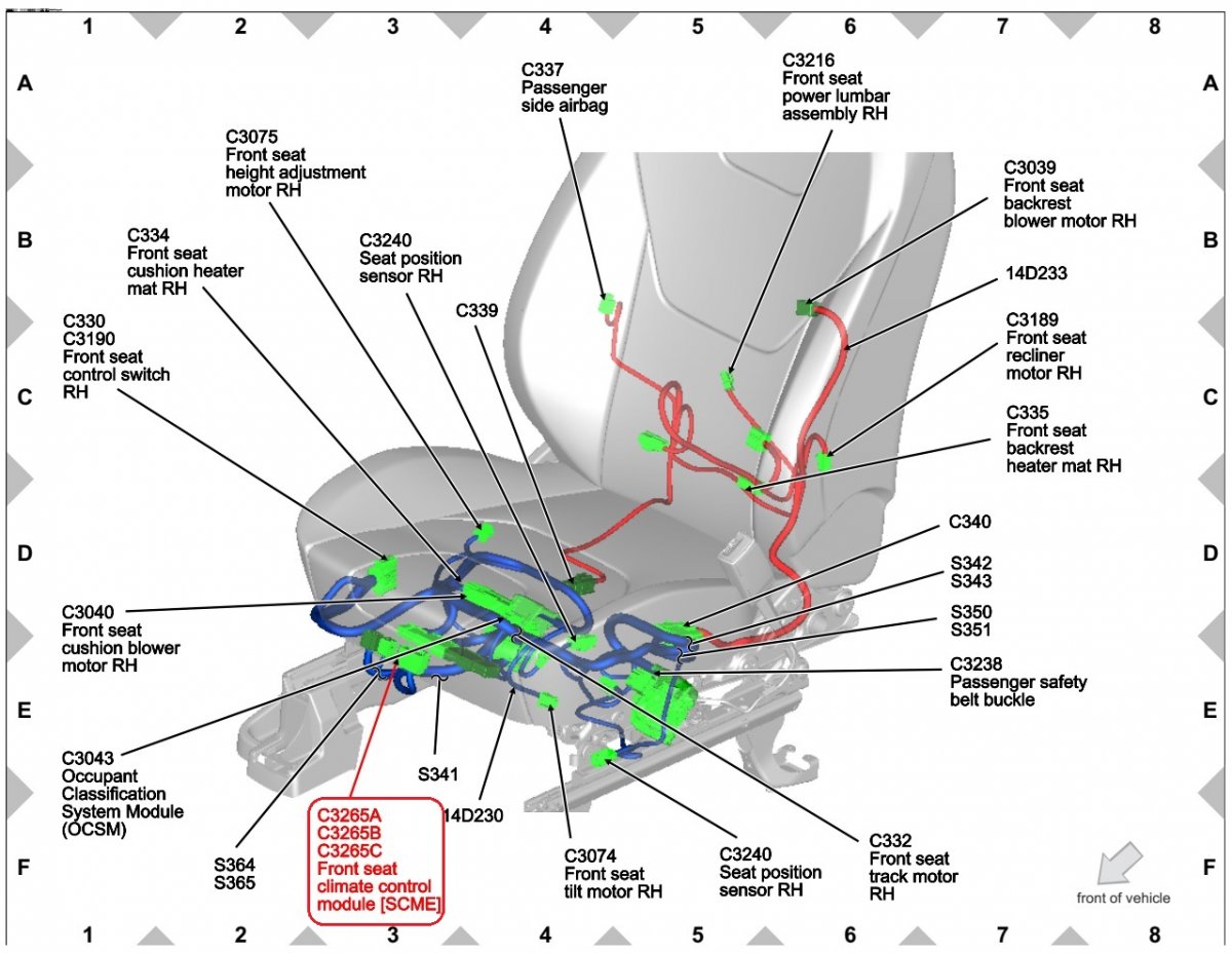
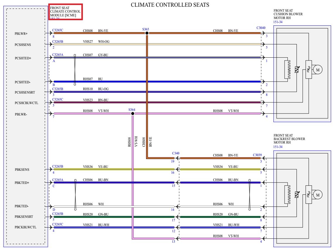
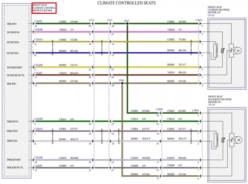
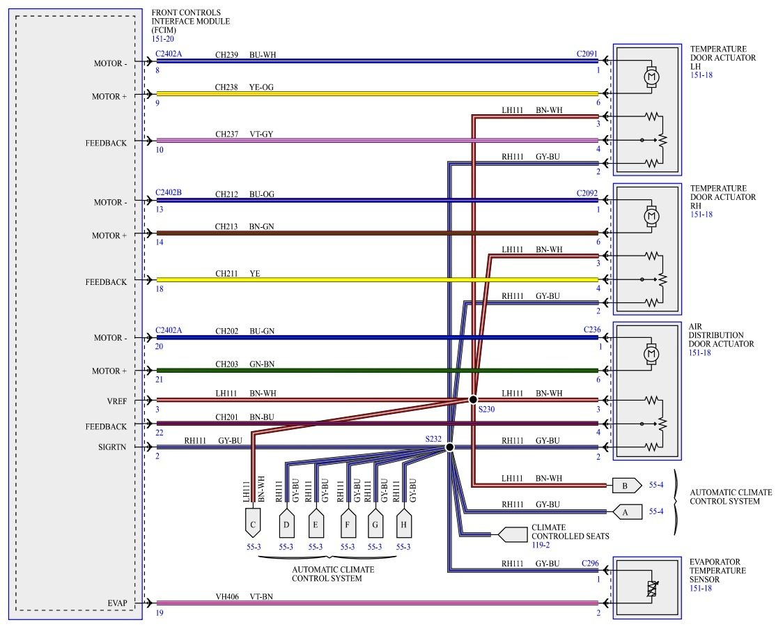
To accomplish your goal of installing the seats and making them fully functional: Buy an Edge Wiring Book in your native language. English language wiring diagrams and connector circuit details are obviously not working... From the document collection you received... Climate Controlled Seats - Wiring Diagram 1 - 2018 Edge.pdf, with Labels added Good luck!
-
Installation of a seat in EDGE SEL from TITANIUM
Haz replied to Yurez's topic in Accessories & Modifications
Per enigma-2's comment on SRS Airbag System precautions... Document download links> Supplemental Restraint System (SRS) Depowering - General Procedures - 2015 Edge Workshop Manual.pdf Supplemental Restraint System (SRS) Repowering - General Procedures - 2015 Edge Workshop Manual.pdf Good luck! -
Installation of a seat in EDGE SEL from TITANIUM
Haz replied to Yurez's topic in Accessories & Modifications
Always hopeful that visualizations are better than a thousand Google-translated words... Driver Seat Module (DSM) - Beneath Driver Seat Front Seat Climate Control Module (SCME) - Beneath Passenger Seat Documents relating to seat-to-seat "adapter cable", as you describe it... Document download links> Front Driver Seat - Connector C311 Details - 2018 Edge.pdf Front Driver Seat - Connector C311 Seat View Location - 2018 Edge.pdf Front Driver Seat - Connector C311 Harness View Location - 2018 Edge.pdf Front Passenger Seat - Connector C312 Details - 2018 Edge.pdf Front Passenger Seat - Connector C312 Location - 2018 Edge.pdf While Titanium-owning Forum members may offer their own hands-on Climate Controlled Seating insights, I am moving on to research other Forum member questions. Once again, speaking directly with Parts & Service personnel at your local Ford dealer will eliminate your need for Google Translate. Good luck!Illustration-BeneathDriverSeat.thumb.jpg.69c0e5e3a9ad74b35dd35bb50791bdac.jpg)
-BeneathPassengerSeat.thumb.jpg.3f4597e10356c5fc64990c6501b8e0ca.jpg)
-
Installation of a seat in EDGE SEL from TITANIUM
Haz replied to Yurez's topic in Accessories & Modifications
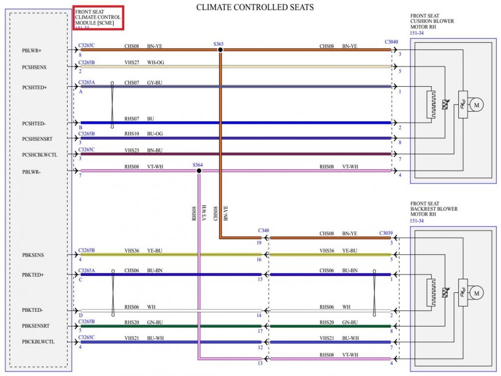
Information about the Front Seat Climate Control Module (SCME), shown in your above photo, was contained in the recently shared document collection, including: Climate Controlled Seats - Wiring Diagram 2 - 2018 Edge.pdf - showing SCME in relation to the Left Hand/Driver's seat... Climate Controlled Seats - Wiring Diagram 3 - 2018 Edge.pdf - showing SCME in relation to the Right Hand/Passenger's seat... FRONT SEAT CLIMATE CONTROL MODULE [SCME] -Connectors C3265A-C3265B-C3265C Location - 2018 Edge.pdf - showing all SCME connectors' relative location... The following documents provide Driver's Seat Module (DSM) connector details on SCME circuits affecting Driver's seat climate control components... Document download links> DRIVER SEAT MODULE (DSM) - Connector C341D Details - 2018 Edge.pdf DRIVER SEAT MODULE (DSM) - Connector C341E Details - 2018 Edge.pdf DRIVER SEAT MODULE (DSM) - Connectors C341D & C341E Location - 2018 Edge.pdf Good luck!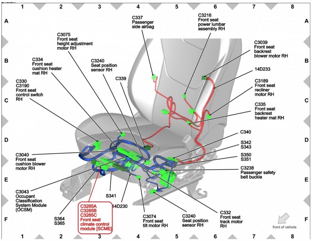
-
The other mechanical switch risks would be the Start/Stop and Transmission Range (TR) switches, which should trigger DTCs. Additional, for the "Library"... Document download links> TIRE PRESSURE MONITOR (TPM) MODULE - Connector C4321 Details - 2011 Edge.pdf TIRE PRESSURE MONITOR (TPM) MODULE - Connector C4321 Location - 2011 Edge.pdf Good luck!
-
The immobilization effect of the Passive Anti-Theft System (PATS) occurs from the interaction of the Intelligent Access (IA) key fob and the Start push button with several electronic modules via related components and circuits in the vehicle. From the 2011 Edge Workshop Manual... (Placing your device cursor over underlined acronyms should result in a popup of the component's full name) Passive Anti-Theft System (PATS) With Intelligent Access (IA) The Passive Anti-Theft System (PATS) consists of the following components: Intelligent Access (IA) key Front passive start antenna (located on the bottom of the front of the floor console) Center passive start antenna (located in the rear of the floor console) Rear passive start antenna (located under the liftgate scuff trim panel, beneath the liftgate striker) Backup transceiver (located in the floor console, below the audio jacks) Tire Pressure Monitor (TPM) module Remote Function Actuator (RFA) module (located behind the glove compartment) Body Control Module (BCM) PCM Starting System - Principles of Operation With IA NOTE: This vehicle is equipped with Passive Anti-Theft System (PATS) that disables the engine if an unprogrammed PATS key is used or an invalid PCM ID is received. PATS is controlled by the Remote Function Actuator (RFA) module. If there is a PATS concern that cause the engine not to crank, the Instrument Panel Cluster (IPC) displays "STARTING SYSTEM FAULT" in the message center. Refer to Section 419-01B to diagnose a PATS concern. The Intelligent Access (IA) starting system is electronically controlled by the RFA module which acts as the PATS control function. The RFA receives the following inputs: Brake pedal applied input Start/stop switch is pressed Transmission in PARK or NEUTRAL signal from the Transmission Range (TR) sensor Run/start relay voltage. Correctly coded ignition key, from the RFA During a start event, the start/stop switch is pressed in combination with the brake pedal, the RFA module and BCM receives a request to start the engine. The RFA module communicates with the BCM . Once the BCM receives the command from the RFA module, it communicates with the PCM. Once the BCM initializes and communicates with the RFA module and the PCM, it checks the ID of each module and compares it with the module ID stored in its own memory. If the RFA module and PCM IDs match the IDs stored in the BCM , then PATS is enabled. The PCM recognizes the correct inputs and provides voltage and ground to energize the starter relay coil and close the starter relay contacts. The starter relay contacts close, providing voltage to the starter solenoid, allowing the starter motor to crank the engine. The PCM disengages the starter motor once an engine rpm threshold is reached, a set crank time is exceeded or the stop/start button is pressed indicating an engine shutdown. Remote Function Actuator (RFA) Module - Principles of Operation The Remote Function Actuator (RFA) module is only equipped when the vehicle has the Intelligent Access (IA) feature. On vehicles equipped with this option, the RFA controls mostly the IA and related entry/anti-theft systems (such as the power door locks and the liftgate release). The RFA module communicates on the Medium Speed Controller Area Network (MS-CAN) . The RFA module controls the following functions: Intelligent Access (IA) feature Keyless entry keypad illumination Liftgate release Passive Anti-Theft System (PATS) Power door locks Remote Keyless Entry (RKE) system The following collection of documents provide fuller detail on component interaction, wiring diagrams and electrical connector details & connector locations, and diagnosis & testing procedures that may equip you, if you choose to identify the root of the problem yourself, or at least, will enhance your awareness if you decide to turn the job over to your dealer's Service technicians. Document download links> Anti-Theft — With Intelligent Access (IA) - Diagnosis and Testing - 2011 Edge Workshop Manual.pdf Starting System - Diagnosis and Testing - 2011 Edge Workshop Manual.pdf Remote Function Actuator (RFA) Module - Diagnosis and Testing - 2011 Edge Workshop Manual.pdf Handles, Locks, Latches and Entry Systems — With Intelligent Access (IA) - Diagnosis and Testing - 2011 Edge Workshop Manual .pdf Tire Pressure Monitoring System (TPMS) - Diagnosis and Testing - 2011 Edge Workshop Manual.pdf Body Control Module (BCM) - Removal and Installation - 2011 Edge Workshop Manual.pdf Body Control Module (BCM) Fuse Protected-Circuits Legend - HIGHLIGHTED - Wiring Diagram - 2011 Edge Workshop Manual.pdf Remote Function Actuator (RFA) Module - Removal and Installation - 2011 Edge Workshop Manual.pdf Remote Function Actuator (RFA) Module - Enhanced Image - 2011 Edge Workshop Manual.pdf Powertrain Control Module (PCM) - Removal and Installation - 2011 Edge Workshop Manual.pdf Tire Pressure Monitor (TPM) Module - Removal and Installation - 2011 Edge Workshop Manual.pdf Passive Anti-Theft System - Wiring Diagram - Cell 112 , Page 02 - 2011 Edge Workshop Manual.pdf Passive Anti-Theft System - Wiring Diagram - Cell 112 , Page 03 - 2011 Edge Workshop Manual.pdf Power Distribution-BCM - Wiring Diagram - Cell 013, Page 12 - 2011 Edge Workshop Manual.pdf Remote Keyless Entry and Alarm - Wiring Diagram - Cell 117, Page 06 - 2011 Edge Workshop Manual.pdf Remote Keyless Entry and Alarm - Wiring Diagram - Cell 117, Page 07 - 2011 Edge Workshop Manual.pdf Remote Keyless Entry and Alarm - Wiring Diagram - Cell 117, Page 08 - 2011 Edge Workshop Manual.pdf Remote Keyless Entry and Alarm - Wiring Diagram - Cell 117, Page 09 - 2011 Edge Workshop Manual.pdf Remote Keyless Entry and Alarm - Wiring Diagram - Cell 117, Page 10 - 2011 Edge Workshop Manual.pdf Starting System -Wiring Diagram - Cell 020, Page 02 - 2011 Edge Workshop Manual.pdf Tire Pressure Monitor System - Wiring Diagram - Cell 118, Page 01 - 2011 Edge Workshop Manual.pdf Backup Transceiver - Connector C3371 Location (Floor Console) - 2011 Edge Workshop Manual.pdf Remote Function Actuator (RFA) Module - Connector C2153A Details - 2011 Edge Workshop Manual.pdf Remote Function Actuator (RFA) Module - Connector C2153B Details - 2011 Edge Workshop Manual.pdf Remote Function Actuator (RFA) Module - Connector C2153C Details - 2011 Edge Workshop Manual.pdf Remote Function Actuator (RFA) Module - Connector C2153D Details - 2011 Edge Workshop Manual.pdf Remote Function Actuator (RFA) Module - Connector C2153E Details - 2011 Edge Workshop Manual.pdf Remote Function Actuator (RFA) Module - Connectors Location (Behind Glovebox) - 2011 Edge Workshop Manual.pdf While I hope these documents cover all the bases for you, please let me know if you recognize a need for anything else. Presumably, your dealer's conclusion about ignition immobilization was based upon Diagnostic Trouble Codes (DTCs) present in your Edge's module(s). If you are personally going to embark upon chasing down potential cause(s), scan or get your Edge scanned to see what DTCs may be present, since they may be cited in the various Diagnosis and Testing documents linked above, and can indicate which Pinpoint Test to employ. Good luck!
-
Adding these, then, for your future reference... Document download links> Cooling Fans Wiring Diagram - Without Trailer Tow - 2007 Edge.pdf Cooling Fans Wiring Diagram - With Trailer Tow - 2007 Edge.pdf COOLING FAN MODULE - Connector C1554 Details and Photo - 2007 Edge.pdf COOLING FAN MODULE - Connector C1554 Location - 2007 Edge.pdf Good luck!
09-20-2023.jpg.406d8706ab9b3a07deea68866dea06bb.jpg)
09-20-2023.jpg.59992e494154935b500c3899d0d1bff7.jpg)
09-20-2023.jpg.970dae23a71887cca97686bcef0a54ac.jpg)

-FordParts.jpg.9b4051decec51f4ab6b39fbd14b6b2d6.jpg)

-ComponentLocation-2015EdgeWorkshopManual.jpg.527f40731e760bf0dda12e44c6efff9c.jpg)
-ComponentLocation-2015EdgeWorkshopManual.jpg.982c11ade0e4b6b5c26e0d35a8b5a921.jpg)
toAirFlowDoorActuatorsWiringDiagram.jpg.83c157551b88b995df5b690e7a6b928a.jpg)
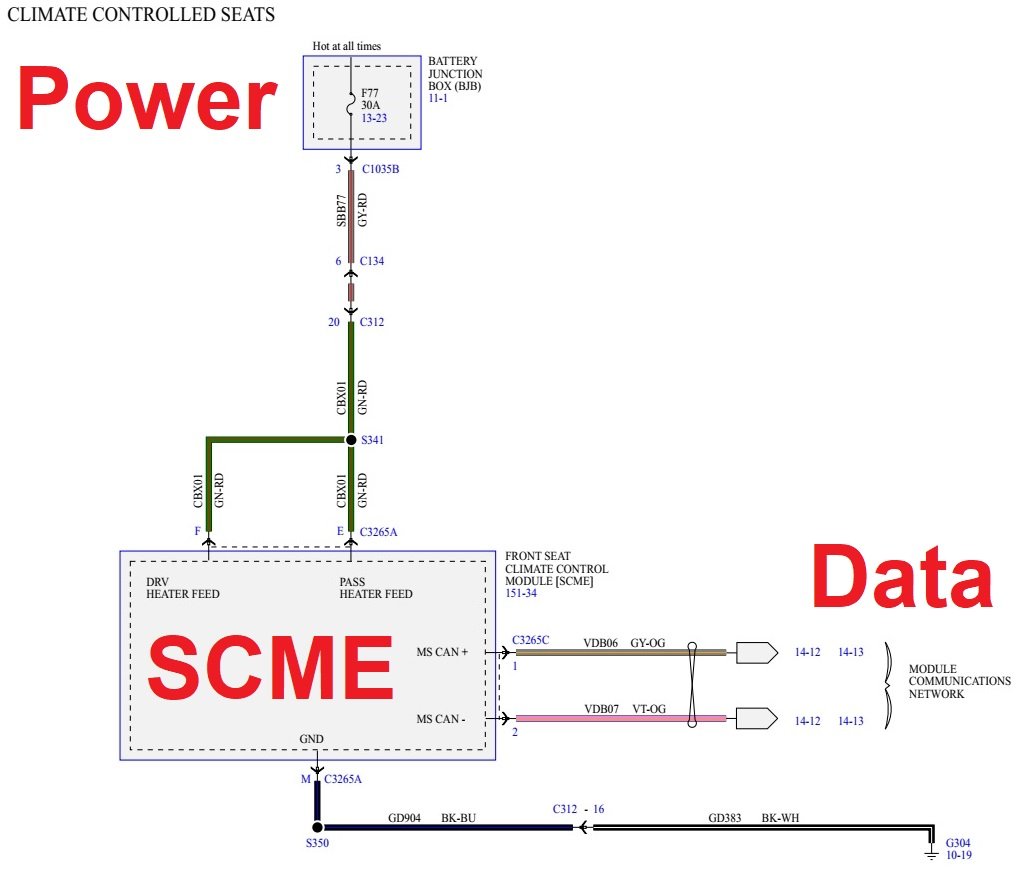

Illustration-BeneathDriverSeat.jpg.e2354ab9a8a3eec2087f39c10f7ca1e9.jpg)
-BeneathPassengerSeat.jpg.b00eff11d9617c095cf869ea2a8e0b6f.jpg)