
Haz
Edge Member-
Posts
1,478 -
Joined
-
Last visited
-
Days Won
396
Content Type
Profiles
Forums
Gallery
Everything posted by Haz
-

2010 Edge power tailgate problems.
Haz replied to Hodgie's topic in Glass, Lenses, Lighting, Mirrors, Sunroof (BAMR), Wipers
For future reference here, from the 2010 Edge Workshop Manual... Placing your device cursor over underlined acronyms may yield full-words descriptions of the acronyms. Power Liftgate Initialization NOTE: The power liftgate may not operate correctly under the following conditions: If any of these conditions has occurred, the power liftgate must be reinitialized. A low voltage or dead battery A disconnected battery Repairs/adjustments have been made to the power liftgate rod, power liftgate motor, liftgate hinges or liftgate striker NOTE: Battery power must be removed from the Liftgate/Trunk Module (LTM) for 20 seconds before the LTM will enter the initialization mode. Disconnect the battery or remove the LTM fuse(s). Wait 20 seconds and reconnect the battery or reinstall the LTM fuse(s). If liftgate is not already in the fully closed position, manually close and fully latch the power liftgate. NOTE: Make sure the power liftgate system is turned ON in the message center before performing this step. NOTE: If the power liftgate does not open during this step, refer to the Symptom Chart to diagnose the inoperative power liftgate. Power open the power liftgate by using the key fob or control switch. Once the power liftgate is fully open, close the power liftgate by using the key fob or control switch. Good luck! -
Welcome to the Forum, @ODPILOT! I had a peculiar and somewhat comparable experience with Forscan and my laptop communicating through our 2015 MKX's Data Link Connector. Intending to monitor a Forscan Dashboard of data points, I started our MKX and began to leave our garage while Forscan was performing its modules scan. While lowering a power window and as the BLIS radar passed the Garage door framing, the window stopped and the BLIS mirror warning lamp remained stuck on. Perplexed, I scanned for DTCs using the then fully-operational Forscan, and several DTCs existed. I cleared those DTCs and the BLISS mirror warning lamp extinguished and power window operation returned. My expectation is Forscan's module communication attempts were interrupted by the activity of the power window and BLIS systems. I'm not immediately familiar with your scanner without downloading and reading its User Guide, but perhaps you can try powering up your scanner with your Edge in Key On Engine Off state -- that is, advancing past Accessory to its Ignition being On, but without performing a Start button push -- since starting your Edge requires brake pedal actuation -- which causes the Powertrain Control Module (PCM) to transmit... Then, try performing a DTC scan to see if any exist, perhaps especially, communications-related "U" codes in the PCM. GWM, or ABS module(s). If any exist, clear them, and see if that extinguishes your Edge's brake lamps. If our MKX hadn't behaved in that past peculiar manner, I wouldn't be offering this advice now. Good luck!
-
Welcome to the Forum, @morrjr71! Congratulations on your moving up from a Fusion SE to your loaded 2021 Edge SEL. We look forward to your ongoing participation here. Good luck!
- 1 reply
-
- 1
-

-
Rear park-stop-turn lamp assembly wiring connectors in the 2010 Edge Wiring resource show involvement with Main Body Harness 14A005, which is depicted as having trunks running down both the left and right sides of the vehicle. Attached as PDF documents are the park-stop-turn wiring diagram, left & right inside rearward views showing labeled 14A005 harness trunks, and left & right inside forward views showing the unlabeled 14A005 harness trunks running at floor level... Good luck! Rear Park-Stop-Turn Lamps - Wiring Diagram - 2010 Edge.pdf Rear Park-Stop-Turn Lamps - 14A005 Harness Location, Inside Right Rearward View - Wiring Diagram - 2010 Edge.pdf Rear Park-Stop-Turn Lamps - 14A005 Harness Location, Outside Rear View - Wiring Diagram - 2010 Edge.pdf Rear Park-Stop-Turn Lamps - 14A005 Harness Location, Inside Left Rearward View - Wiring Diagram - 2010 Edge.pdf Rear Park-Stop-Turn Lamps - 14A005 Harness Location, Inside Right Forward View - Wiring Diagram - 2010 Edge.pdf Rear Park-Stop-Turn Lamps - 14A005 Harness Location, Inside Left Forward View - Wiring Diagram - 2010 Edge.pdf
-
Document download links> 2025 Lincoln Nautilus U.S. Order Guide.pdf 2025 Lincoln Nautilus Canada Order Guide.pdf 2025 Lincoln Aviator U.S. Order Guide.pdf
-
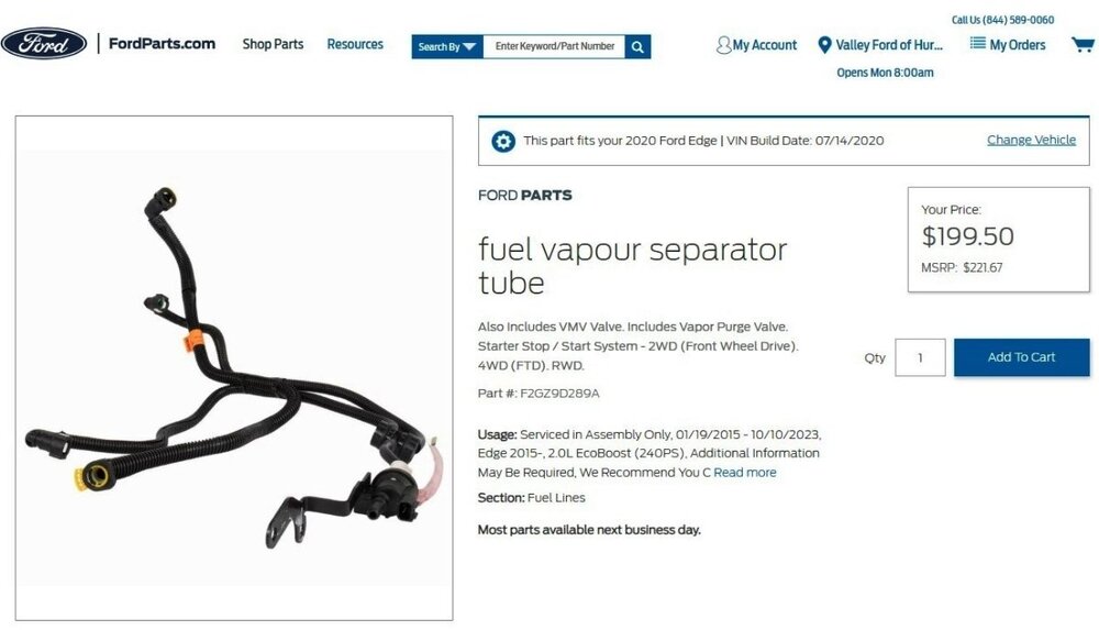
As @atulo indicates, with this result from using VIN from a 2020 Edge Titanium 2.0L EcoBoost... Relevant sections from the 2020 Edge Workshop Manual are attached below as PDF documents... Good luck! Evaporative Emission Canister Purge Valve - 2.0L EcoBoost - Removal and Installation - 2020 Edge Workshop Manual.pdf Quick Release Coupling - 2.0L EcoBoost - Removal and Installation - 2020 Edge Workshop Manual.pdf
-

08MKX automatically starts byself
Haz replied to Holdog101's topic in Alarms, Keyless Entry, Locks & Remote Start
Remote Starting was not an option offered on 2008 MKX, so as @dabangsta describes, the faulty double-lock-actuated starting system is surely not factory installed. Lincoln Accessories offered a dealer-installed Remote Start system for MKX in 2008, but it utilized a separate fob and was not activated by a double-lock button push using the physical key fob. Because there's no starting deterrence with the hood ajar, perhaps somewhere in the engine compartment, there is a warning sticker saying the vehicle is equipped with a remote starting system, which may also provide some indication of the system's manufacturer to obtain their troubleshooting guide. If it was the vehicle battery which you replaced, maybe the aftermarket system returned to a default configuration which needs to be restored to its previous compatibility with your MKX. Attached below as PDF documents are the 2008 MKX Sales Brochure, and, a Diagnosis Guide for the Lincoln Accessories system, though the Diagnosis Guide does not mention the symptom your MKX is exhibiting. Good luck! 2008 MKX Sales Brochure.pdf Ford Powercode Remote Start System - Diagnosis Guide -Rev 1.pdf -
Welcome to the Forum, @Glendaa! Without addressing the several functional peculiarities that you describe, let's focus upon your Edge's Parasitic Battery Drain issue. Ford has a very detailed procedure for finding and correcting the causes of Parasitic Battery Drain. While you might wish to lightly review the following Forum discussion and Diagnostic video, it may be worthwhile to share these with your Mechanic to see if the Mechanic's past diagnostic efforts approach what is described and depicted in the linked Parasitic Battery Drain diagnostic procedure video. Parasitic Battery Drain Forum Discussion https://www.fordedgeforum.com/topic/32515-parasitic-drawbattery-drain-diagnostic-procedure-workshop-manual-revision-january-2024/ Parasitic Battery Drain Diagnostic Procedure Video https://players.brightcove.net/5803674275001/experience_5ee12f39b12d440025e025f6/share.html If you cannot e-mail your Mechanic the above web links, you can print this comment and the Mechanic can manually input the web addresses into his/her computer or other Internet-capable device. Good luck!
-
Are you saying you are changing As-Built values within or among Modules you are incrementally installing? That DTC indicates the IPMA's As-Built values are not correct. Do you have As-Built values from an Edge that is factory configured and programed to your Edge's desired future-state of installed modules for the features you are adding? Good luck!
-

08MKX automatically starts byself
Haz replied to Holdog101's topic in Alarms, Keyless Entry, Locks & Remote Start
Welcome to the Forum, @Holdog101! More as an experiment than as an attempt toward an interim fix (if it works)... Try popping the hood release -- in order to trip the Hood Ajar switch -- before closing the locked door, and if the vehicle does not "auto-start", then push down on the hood to re-latch it, and see what the vehicle does. If that works, fuller diagnostic efforts are absolutely necessary to affect a permanent root-cause correction. Good luck! -
Welcome to the Forum, @whiffle! You may want to look at this past discussion, which is equivalent to an Edge SEL cluster being swapped into an Edge SE. Good luck!
-
Headlamp Assembly - Removal and Installation - 2022-2024 Edge workshop Manual.pdf Good luck!
-
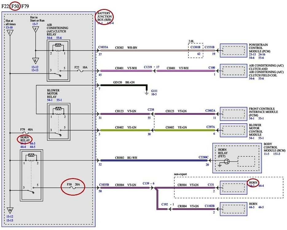
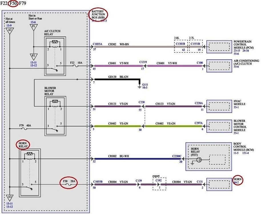
From the 2020 & 2024 Edge Wiring Resource, the horn circuit is protected with a 20-amp fuse, as shown in the wiring diagrams below... And the 2024 Edge Wiring Diagram... Information of the Horn electrical connector C131 is attached below as a PDF document... Good luck! Horn - Connector C131 Circuits-Pins Details - 2020 & 2024 Edge.pdf
-
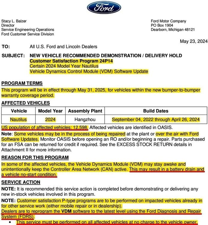
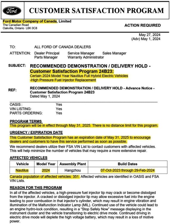
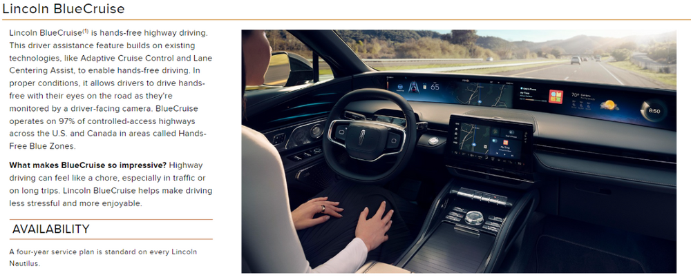
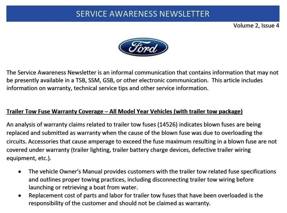
TECHNICAL SERVICE BULLETIN 2024 Nautilus - Inaccurate Clock, Google Map Not Displaying, And/Or Weather Not Updating Along With The Inability To Sign Into Google Automotive Services To Edit A Profile 24-2175 29 May 2024 Model: Lincoln 2024 Nautilus Issue: Some 2024 Nautilus vehicles may have a clock that is inaccurate and/or weather information may not be able to update along with the inability to sign-in to Google Automotive Services to update or edit a profile. During this time the Google Map may also not display in the panoramic display screen next to the speedometer. This may be due to a concern with the TCU software. NOTE: It is normal for the Google Map to not appear in the panoramic display when in calm mode or when using the Waze app. NOTE: The TCU software update that addresses the symptom listed in this article may have been delivered OTA to connected vehicles that have automatic updates enabled through the vehicle's center display screen. Enter the VIN in PTS and check the OTA Dashboard under the Connected Vehicle tab for OTA update history. If an update to the APIM has successfully completed recently and the customer is reporting the symptoms are no longer present, this article may not apply. Action: Follow the Service Procedure to correct the condition on vehicles that meet all of the following criteria: Warranty Status: Eligible under provisions of New Vehicle Limited Warranty (NVLW)/Service Part Warranty (SPW)/Service Part New Vehicle (SPNV)/Extended Service Plan (ESP) coverage. Limits/policies/prior approvals are not altered by a TSB. NVLW/SPW/SPNV/ESP coverage limits are determined by the identified causal part and verified using the OASIS part coverage tool. Labor Times Description Operation No. Time 2024 Nautilus: Reprogram The Appropriate Modules As Required By The Software Update And Service Procedure (Do Not Use With Any Other Labor Operations) MT242175 Actual Time Attached below as a PDF document is the full Technical Service Bulletin, including the Service Procedure which utilizes the Ford Diagnosis and Repair System (FDRS) to perform the prescribed Software Update(s)... TSB 24-2175 - 2024 Nautilus - Clock, Google Map. Weather, Google Automotive Services Issues.pdf
-
It is worth noting that Edge and Nautilus are not among the product lines listed for Over-The-Air (OTA) delivery of the expected 4th Quarter 2024 APIM update currently under development -- necessitating a visit to the dealership for Edge and Nautilus vehicles to have this eventual update installed, per emphasis added below... SSM 52574 - Vehicles Equipped with SYNC 4 - Intermittent Symptoms After All Available Software Updates Performed - Awareness of Solutions Being Developed Some vehicles equipped with SYNC 4 may exhibit one or more of the following symptoms after all currently available accessory protocol interface module (APIM) software updates have been performed. - General system performance, stability, and intermittent system reboots. - Intermittent Wireless CarPlay or Android Auto function. - Phone related concerns with intermittent No Audio or Static. - Navigation/global positioning system (GPS) related concerns through CarPlay and Android Auto. - Alexa function consistency and stability. These symptoms may be due to the software in the APIM. Replacing the APIM will not resolve these symptoms for the customer. Before returning the vehicle to the customer, review the procedures within Workshop Manual, Section 415-00 and ensure the latest APIM software is installed. Refer to General Service Bulletin (GSB) 23-7146 for help determining the latest available level of software. IMPORTANT: some module software updates will only display as available on Ford Diagnosis and Repair System (FDRS) after prerequisite modules are updated. This may require the technician to update certain modules multiple times during the service visit, before the latest APIM software is accessible in FDRS. If symptoms continue after latest APIM software has been installed, inform customers that Ford is working on additional software enhancements which are expected to be delivered over-the-air (OTA) by Q4 2024 on F-150, F-150 Lightning, Mustang Mach-E, Mustang, Escape, Corsair, Expedition, Navigator, Bronco, Mustang, and 2023-2024 F-Super Duty. Software will update automatically if vehicle connectivity is enabled in the vehicle's settings. For all other vehicles with SYNC 4, schedule a service visit for customers in October 2024, when the updated APIM software is expected to be available to dealers. Monitor OASIS for additional information.
-
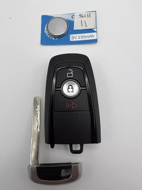
Providing information here, previously shared with @pjtaxi via Forum Messaging, regarding the initial key fob post... Thanks for providing me your Edge's VIN, which allowed me to call up a Ford report called the Historical Vehicle Bill of Material (HVBoM), which lists the original part numbers of all identified parts assembled into your specific Edge. The HVBoM states the original Ford part number for the keyless entry fobs supplied with your Edge was HC3T-15K601-AD. This is the three-button fob that you've describing as currently having. (This image is from an inactive eBay ad from which the fobs are sold out) Presently, the Ford part number to replace the originally supplied fobs is HC3Z-15K601-G. Good luck!
-
From the 2020 Edge Workshop Manual, with emphasis added... Placing your device cursor over underlined acronyms may yield full-words popup descriptions of their meaning. Arming The Perimeter Alarm The perimeter alarm is ready to arm any time the ignition is off. The perimeter alarm pre-arms when any of the following actions are carried out: Pressing the lock button on a RKE transmitter Pressing the door lock control switch to the lock position with a front door open, and then closing the door Touching the 7/8 and 9/0 buttons simultaneously on the keyless entry keypad Locking the vehicle with the passive entry feature Once the system is pre-armed, there is a 20-second countdown before the perimeter alarm is armed. Each entry point to the vehicle (hood, door and liftgate) is armed separately and must be closed before that entry point begins the 20-second countdown to become armed. If all entry points are closed, the turn signals flash upon locking to indicate all entry points are entering the 20-second countdown. Perimeter Alarm Activation The perimeter alarm has a 12-second delay when the driver front door is opened without using a valid programmed RKE transmitter, the keyless entry keypad or a passive key to unlock the vehicle. During the delay, a chime sounds. If the perimeter alarm is not disarmed within the 12-second delay, the alarm activates. The perimeter alarm activates when any of the following actions are carried out: The driver front door is opened without first receiving an unlock command from the passive entry feature, the keyless entry keypad or a valid programmed RKE transmitter, and the 12-second delay has expired. Any other door, the liftgate or the hood is opened without first receiving an electronic unlock command from the passive entry feature, the keyless entry keypad or a valid programmed RKE transmitter. the BCM detects an attempt by a diagnostic scan tool to establish communication on the CAN . The perimeter alarm only activates 10 times per arming cycle. After that, the alarm does not activate. To enable the perimeter alarm again, disarm the perimeter alarm and then arm it again. Disarming The Perimeter Alarm The perimeter alarm disarms when any of the following actions are carried out: Pressing the unlock button on a door lock control switch within the 20-second pre-arm The smart unlock feature activates within the initial 20-second pre-arm Pressing the unlock button on a valid programmed RKE transmitter Pressing the liftgate release button on a programmed RKE transmitter (this only disarms the liftgate entry point with the rest of the vehicle remaining armed) Using a valid programmed key to change the ignition to RUN Entering the correct vehicle unlock code on the keyless entry keypad Unlocking a front door or opening the liftgate using the passive entry feature The source of the above description is attached below as a PDF document... Good luck! Perimeter Anti-Theft Alarm - System Operation and Component Description - 2020 Edge Workshop Manual.pdf
-
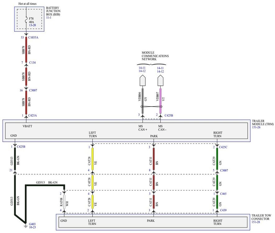
Welcome to the Forum, @Bbunker66! The following 2019 Edge Wiring Diagram depicts the circuits provided in the Trailer Tow Package... Trailer Module (TRM) Location Trailer Module (TRM) Installed Good luck! Trailer Tow Connector Wiring Diagram - 2019 Edge.pdf Trailer Module (TRM) - Location Illustration - 2019 Edge.pdf
-
Attached below as PDF documents are the EGR and DPFE sensor removal and installation procedures for 2.0L EcoBoost from the 2019 Edge Workshop Manual, and, location illustrations from the 2019 Edge Wiring resource... Good luck! Exhaust Gas Recirculation (EGR) Valve - Removal and Installation - 2019 Edge Workshop Manual.pdf Differential Pressure Feedback Exhaust Gas Recirculation (EGR) Sensor - Removal and Installation - 2019 Edge Workshop Manual.pdf EXHAUST GAS RECIRCULATION (EGR) VALVE - 2.0L EcoBoost Location - 2019 Edge.pdf Differential Pressure Feedback Exhaust Gas Recirculation (EGR) Sensor - 2.0L EcoBoost Location - 2019 Edge.pdf





-InstalledIllustration-2019Edge.jpg.285c6b213cb6c8cac646eda9baa9c5f8.jpg)
-LocationIllustration-2019Edge.thumb.jpg.039ed8715abe898d8e8bfef4d65dd495.jpg)
