


Haz
-
Posts
1,460 -
Joined
-
Last visited
-
Days Won
392
Everything posted by Haz
-
Oil Filter Inspection Special Tool(s) / General Equipment Oil Drain Equipment Knife Vise Activation Remove the oil filter. Refer to oil change. Drain any excess oil from the oil filter. Use the General Equipment: Oil Drain Equipment Using an oil filter cutter, cut the housing from the baseplate. Remove the support tube and oil filter element assembly from the housing. Separate the oil filter element from the support tube. Use the General Equipment: Knife Use the General Equipment: Vise Twist the top and bottom endcaps and separate the top or bottom endcaps from the support tube. Inspect the support tube for debris. Check for metal debris, fine or course, that would indicate a catastrophic failure of the engine. Expand the oil filter element. Normal element, a few particles of metal is normal. Bearing damage, large amount of bearing metal is not normal. If the oil filter inspection shows excessive metal debris to indicate catastrophic failure of the engine, REMOVE the engine oil pan and inspect the main and connecting rod bearings for damage. DISASSEMBLE the engine to determine the extent or source of the damage. REFER to Engine Oil Pan. REFER to Removal. REFER to Bearing Inspection. REFER to Engine Disassembly. © Copyright 2025, Ford Motor Company. Oil Filter Inspection - Workshop Manual General Procedure.pdf
-
Once again, perhaps unnecessary due to your replacement of the Master Cylinder, but with emphasis below, and additional PDF Workshop Manual sections... Brake Master Cylinder Compensator Ports The purpose of the compensator ports in the brake master cylinder is to supply additional brake fluid from the master cylinder reservoir when needed by the brake system due to brake lining wear and allow brake fluid to return to the master cylinder reservoir when the brakes are released. The returning brake fluid creates a slight turbulence in the master cylinder reservoir. This is a normal condition and indicates that the compensator ports are not clogged. Clogged compensator ports may cause the brakes to hang up or not fully release. Good luck! Brake System - Principles of Operation - 2013 Edge Workshop Manual.pdf Front Disc Brake - Specifications - 2013 Edge Workshop Manual.pdf Brake Caliper - Removal and Installation - 2013 Edge Workshop Manual.pdf Component Bleeding - General Procedures - 2013 Edge Workshop Manual.pdf Brake System Bleeding - General Procedures - 2013 Edge Workshop Manual.pdf
-
@sounduser: Your question may be addressed by the U.K. edition Workshop Manual sections attached below as PDF documents... Please note that I selected 177kW/240PS EcoBlue information -- if you require the lower output EcoBlue information, just let me know and I will provide it. Good luck! Engine - System Operation and Component Description - 2.0L EcoBlue Diesel - 2015-2022 Edge, Edge Vignale, Endura Workshop Manual.pdf Engine Component Location - Description and Operation - 2.0L EcoBlue Diesel - 2015-2022 Edge, Edge Vignale, Endura Workshop Manual.pdf Timing Belt - Removal and Installation - 2.0L EcoBlue Diesel - 2015-2022 Edge, Edge Vignale, Endura Workshop Manual.pdf Timing Belt Cover - Removal and Installation - 2.0L EcoBlue Diesel - 2015-2022 Edge, Edge Vignale, Endura Workshop Manual.pdf
-
Welcome to the Forum @Todd Turner! Your described repair efforts indicate this question may be unnecessary, but since you don't mention performing a Programmable Module Installation (PMI) procedure: When the ABS Module was replaced, did you configure the new ABS Module using the As-Built values contained in the ABS Module you removed? Also, when the brake lock-up symptom occurs, are you hearing the ABS pump activating? Relevant sections from the 2013 Edge Workshop Manual and Wiring Resource are attached below as PDF documents... Good Luck! Brake Pedal and Bracket - Removal and Installation - 2013 Edge Workshop Manual.pdf BRAKE PEDAL POSITION (BPP) SWITCH - Connector C2064 Pinout Diagram - 2013 Edge.pdf BRAKE PEDAL POSITION (BPP) SWITCH - Connector C2064 Location - 2013 Edge.pdf BRAKE PEDAL POSITION (BPP) SWITCH - Power Distribution Wiring Diagram - 2013 Edge.pdf Stoplamp Switch - Removal and Installation - 2013 Edge Workshop Manual.pdf Component Tests - Brke System Diagnosis and Testing - 2013 Edge Workshop Manual.pdf Hydraulic Control Unit (HCU) - Removal and Installation - 2013 Edge Workshop Manual.pdf Pinpoint Test C - DTCs C0044.28, C0044.49 and C0044.64 - Diagnosis and Testing - 2013 Edge Workshop Manual.pdf Wheel Speed Sensor — Front - Removal and Installation - 2013 Edge Workshop Manual.pdf
-
Historical references attached below as PDF documents... Good luck! Customer Satisfaction Program 19N09 - Left Front Door Latch Extended Coverage - 12-12-2019 - Dealer Bulletin.pdf Customer Satisfaction Program 19N09 - Left Front Door Latch Extended Coverage - 12-12-2019 - Technical Instructions.pdf TSB 18-2013 - Door Ajar Lamp Remains Illuminated When Doors Closed.pdf
-
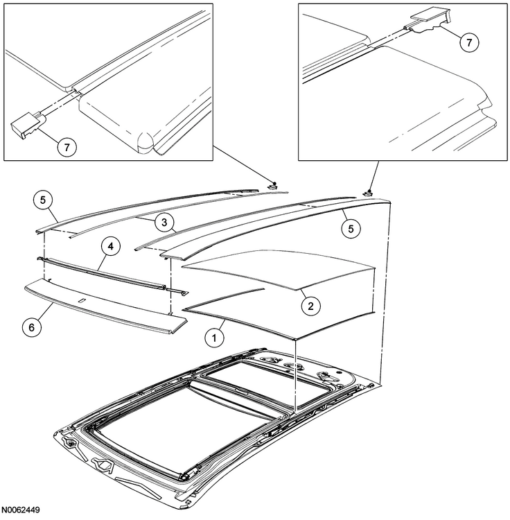
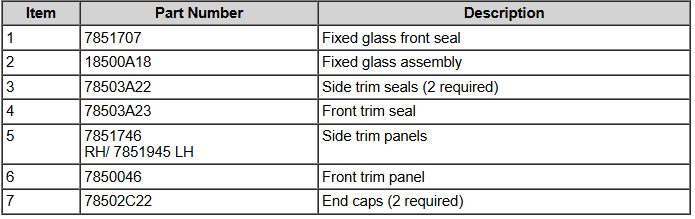
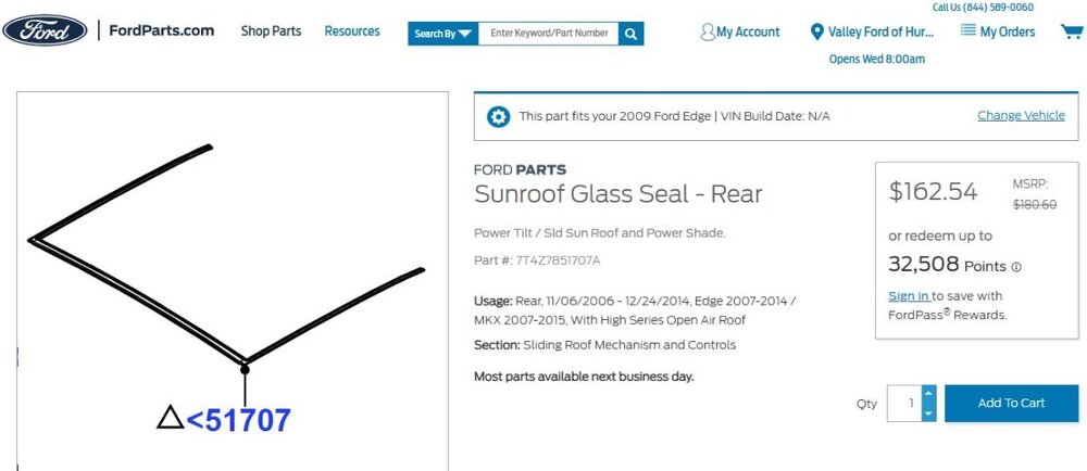
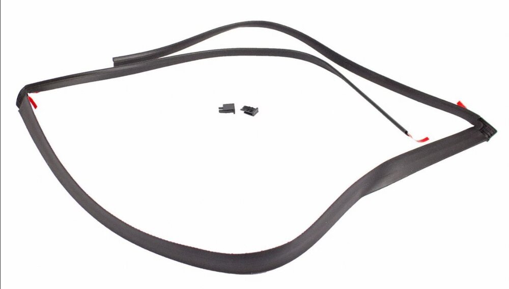
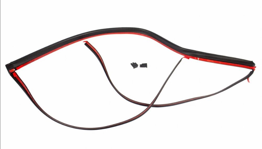
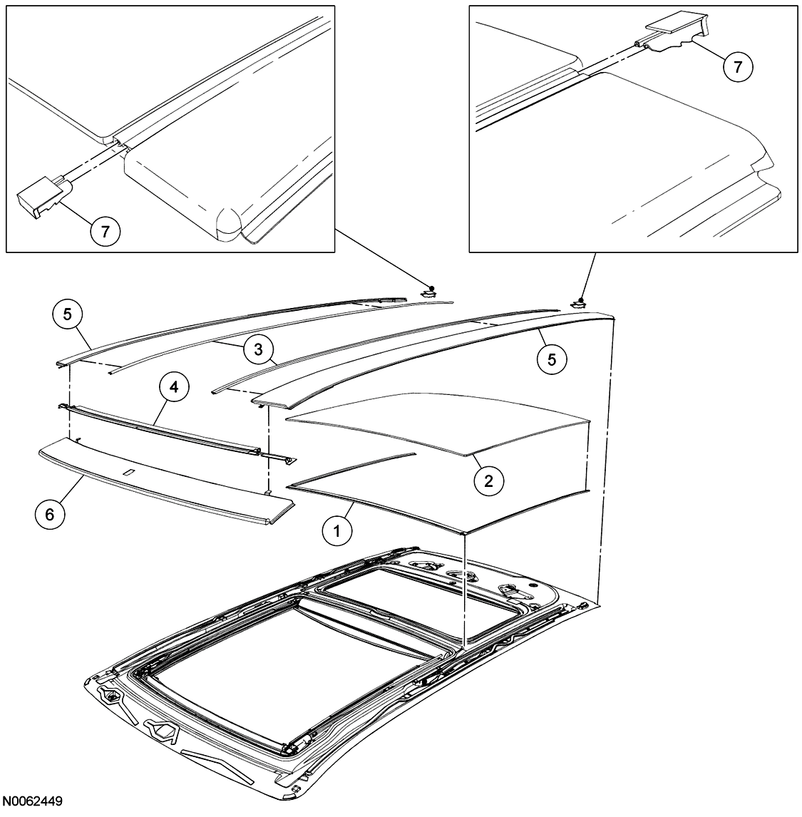
@edgemaster: The 2009 Edge Workshop Manual provides the following illustration showing the Fixed Glass panel of your Edge's Panoramic Roof. You are describing the U-shaped Fixed Glass Front Seal (item 1), which along with the two Side Trim Seals (item 3) fill the gaps at the front and on the left & right sides of the Fixed Glass panel, where channels exist to drain water to the rear of the roof, where it flows out through the left & right side End Caps (item 7)... As you may already know, the waterproof sealing of the Fixed Glass panel is provided by a continual bead of urethane adhesive applied to the metal roof structure in the shape of Path 1 or Path 2, depending upon the model year of the Edge/MKX... Ford's parts-selling website offers photos of the Front seal which may be helpful, and which appears to show the red pull-off strip for double-sided tape used to affix the Front seal to the roof, underneath the outer edges of the Fixed Glass panel... Link to this FordParts webpage The Workshop Manual does not provide any procedure relating to removal and installation of the Front seal. If it did, I expect because of the minimal clearance between the Front seal's left-hand & right-hand side legs and the seals on the Side Trim pieces, the procedure might involve removal of the Fixed Glass panel by cutting the bead of urethane sealant, cleaning residue from the glass panel and the metal roof, then installing of the Front seal on the roof, apply the continuous bead of urethane sealant, and install the Fixed Glass panel, all of which would very likely involve a professional glass installer. Working clearances between the rear of the Moving Glass panel and the front of the Fixed Glass panel are greater, however, so if the Front seal is only deteriorated on the front, then it might be possible to cut the existing Front seal away from its side legs, and similarly cut the replacement Front seal after clearing away all remaining rubber from underneath the front edge of the Fixed Glass panel. I would say, before attempting any of this, it would be prudent to use a feeler gage to assess how much clearance or compression-on-the-seal exists between the bottom of the glass panel and the metal rooftop. If the double-sided-taped seal cannot be freely inserted and affixed underneath the front edge of the Fixed Glass panel, then I expect, services of a professional glass installer may be needed - at a much higher cost. Good luck! Roof Opening Panel Glass — Rear Fixed - Removal and Installation - 2009 Edge Workshop Manual.pdf Roof Opening Panel — Exploded View Illustrations - 2009 Edge Workshop Manual.pdf

-
2011 Ford Edge Rear Suspension Torque Specs Needed
Haz replied to mdk1016's topic in Brakes, Chassis & Suspension
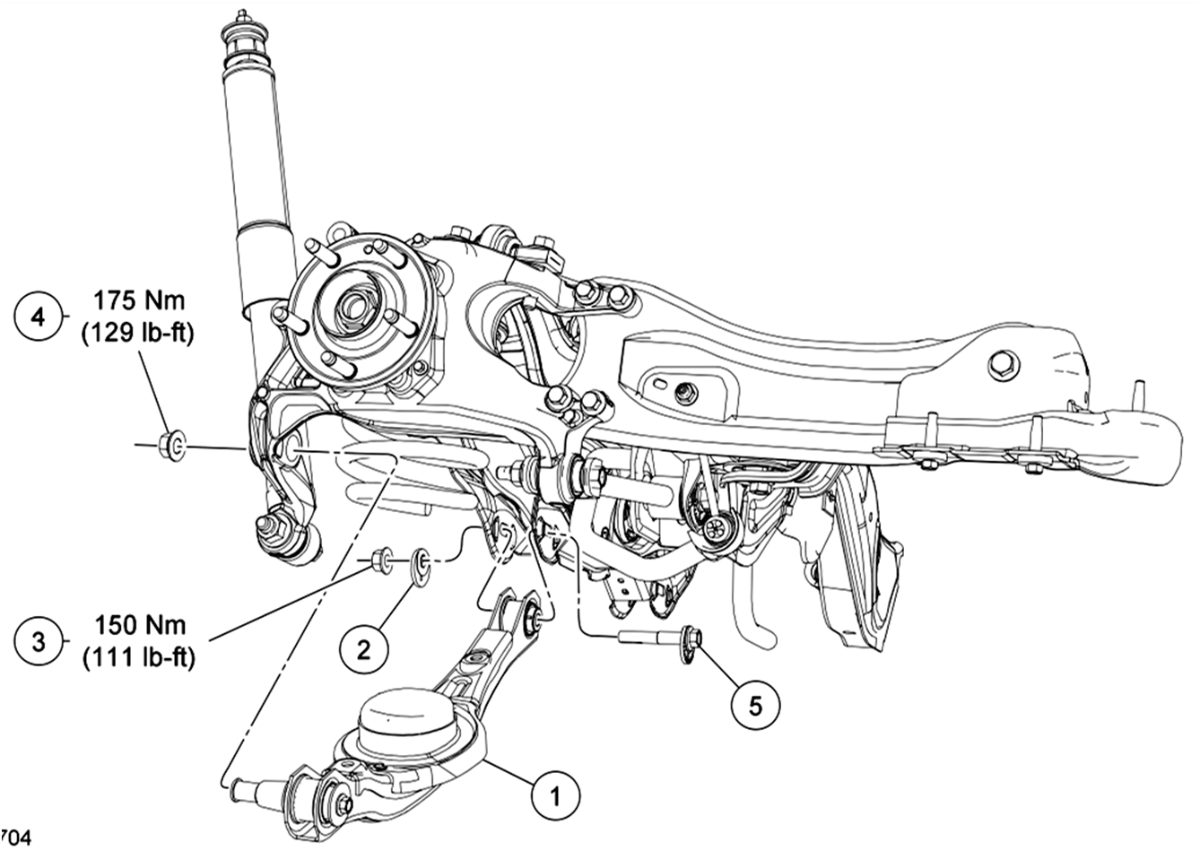
Lower Arm illustration and guidance from the Workshop Manual... NOTICE: Suspension fasteners affect performance of vital components and systems and their failure may result in major service expense. If replacement is necessary install new parts with the same part numbers or equivalent part. Do not use a replacement part of lesser quality or substitute design. Tighten the fasteners to specification during reassembly. NOTICE: Tighten the suspension bushing fasteners with the weight of the vehicle resting on the wheels and tires or incorrect clamp load and bushing damage may occur. Good luck!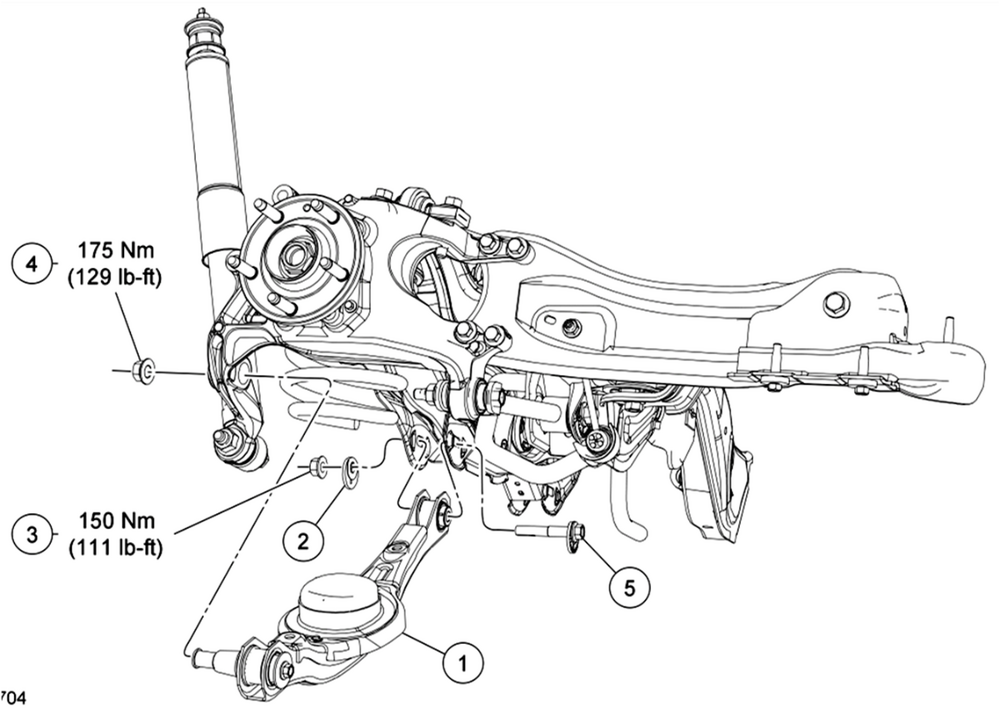
-
2011 Ford Edge Rear Suspension Torque Specs Needed
Haz replied to mdk1016's topic in Brakes, Chassis & Suspension
Welcome to the Forum @mdk1016! From the 2011 Edge Workshop Manual... Rear Suspension Torque Specifications Description Nm lb-ft lb-in Lower arm cam adjuster nut 150 111 — Lower arm outboard nut 175 129 — Parking brake cable bolt 18 — 159 Shock absorber lower nut 225 166 — Shock absorber upper nut 25 18 — Stabilizer bar bracket nut 55 41 — Stabilizer bar link upper and lower nut 40 30 — Toe link inboard nut 200 148 — Toe link outboard nut 175 129 — Upper arm inboard nut 175 129 — Upper arm outboard bolts 175 129 — Wheel hub and bearing bolt 115 85 — Wheel hub nuta — — — Trailing arm bracket-to-frame bolts 48 35 — Trailing arm nut 150 111 — Wheel knuckle-to-trailing arm nuts 103 76 — Wheel speed sensor bolt 7 — 62 Rear Drive Axle/Differential Torque Specifications Description Nm lb-ft Differential housing cover bolts 23 17 Differential housing-to-front insulator bracket bolts 90 66 Filler plug 29 21 Front insulator bracket-to-subframe bolts 90 66 Pinion flange nut 244 180 Rear driveshaft U-joint flange bolts 70 52 Side insulator bracket-to-rear axle differential bolts 90 66 AWD vehicles NOTICE: Do not tighten the rear wheel hub nut with the vehicle on the ground. Tighten the wheel hub nut to specification before the vehicle is lowered to the ground. Wheel bearing damage occurs if the wheel bearing is loaded with the weight of the vehicle applied. NOTE: Apply the brake to keep the halfshaft from rotating. Position the halfshaft in the wheel hub and bearing assembly and use the previously removed wheel hub nut to seat the halfshaft. Tighten to 350 Nm (258 lb-ft). Remove and discard the wheel hub nut. NOTICE: Install and tighten the new wheel hub nut to specification within 5 minutes of starting it on the threads. Always install a new wheel hub nut after loosening, or when not tightening within the specified time, or damage to the components may occur. Install a new wheel hub nut. Tighten to 350 Nm (258 lb-ft). Good luck! -
TECHNICAL SERVICE BULLETIN Misfire With DTC(s) P0301, P0302, P0303, And/Or P0304 Stored In The PCM 25-2074 06 March 2025 This bulletin supersedes 24-2384. Reason for update: vehicle models affected Model: Ford 2025 Bronco Engine: 2.3L EcoBoost 2023-2025 Escape Engine: 1.5L EcoBoost Engine: 2.0L EcoBoost 2025 Explorer Engine: 2.3L EcoBoost 2024-2025 Mustang Engine: 2.3L EcoBoost 2025 Ranger Engine: 2.3L EcoBoost Lincoln 2023-2025 Corsair Engine: 2.0L EcoBoost 2024-2025 Nautilus Engine: 2.0L EcoBoost Engine: 2.0L EcoBoost Hybrid Markets: North American markets only Issue: Some of the vehicles listed in the Model statement above may exhibit an engine misfire condition with DTCs P0301, P0302, P0303 and/or P0304 set in the PCM. Action: For vehicles that meet all of the criteria in the Issue and Model statements, follow the Service Procedure to diagnose the vehicle. Warranty Status: Information Only. Repair/Claim Coding Causal Part: IN Condition Code: -1 Service Procedure NOTE: This article is for information only. Determine the causal part number and use available labor times in the SLTS Manual or claim M-time in accordance with the Warranty and Policy Manual, do not use this article number as the M-Time labor operation. Causal part number IN in this article refers to the information only status and is not able to be claimed. 1. Remove and inspect the condition of all spark plugs. Refer to the WSM, Section 303-07. Are any spark plugs damaged? (1). Yes - proceed to Step 2. (2). No - this article does not apply, replacement of the spark plugs is not necessary, proceed with normal diagnostics found in the WSM. 2. Inspect the 12v battery positive and negative terminals for a loose condition, refer to WSM, Section 414-01 and repair as necessary. 3. Inspect all PCM ground circuitry for loose connections and/or high resistance and repair as necessary. 4. Use a borescope to inspect the condition of the affected pistons and cylinder walls. Refer to Figures 1-3 for examples of normal cylinder wall wear and Figures 4-5 for examples of damaged cylinder walls. Additional examples of engine wear can be found in the Engine Failure Analysis GSB > Cylinder Wall and Piston Skirt Inspection. Do the pistons and/or cylinder walls appear to be damaged? Figure 1 - Showing normal cylinder wall wear Figure 2 - Showing normal cylinder wall wear Figure 3 - Showing normal cylinder wall wear Figure 4 - Showing a damaged cylinder wall Figure 5 - Showing a damaged cylinder wall (1). Yes - remove the cylinder head to perform a more detailed inspection of the suspect damage. Refer to the Engine Failure Analysis GSB > Cylinder Wall and Piston Skirt Inspection and repair as necessary. For cylinder head removal, refer to the WSM, Section 303-01. (2). No - perform a compression test and cylinder leakage test following WSM, Section 303-00 and repair as necessary. 5. Replace all damaged spark plugs. Do not discard the damaged spark plugs so Ford can retrieve them following the warranty parts return process. 6. Submit a GCR and include photos of damaged components, images from the borescope analysis and anything else of interest that was found during the repair. These images will help improve engine quality for future model vehicles. (1). Do not use the Report A Problem link to submit the GCR. © 2025 Ford Motor Company All rights reserved. NOTE: The information in Technical Service Bulletins is intended for use by trained, professional technicians with the knowledge, tools, and equipment to do the job properly and safely. It informs these technicians of conditions that may occur on some vehicles, or provides information that could assist in proper vehicle service. The procedures should not be performed by "do-it-yourselfers". Do not assume that a condition described affects your car or truck. Contact a Ford or Lincoln dealership to determine whether the Bulletin applies to your vehicle. Warranty Policy and Extended Service Plan documentation determine Warranty and/or Extended Service Plan coverage unless stated otherwise in the TSB article. The information in this Technical Service Bulletin (TSB) was current at the time of printing. Ford Motor Company reserves the right to supersede this information with updates. The most recent information is available through Ford Motor Company's on-line technical resources. TSB 25-2074 - Misfire With DTCs P0301, P0302, P0303, And-Or P0304 Stored In The PCM - 03-06-2025.pdf
-
It's worth noting that a visit to the dealership is required for correction, and that no impending OTA update is mentioned as an alternative remedy. Thanks, Bunky!
- 1 reply
-
- 2
-

-
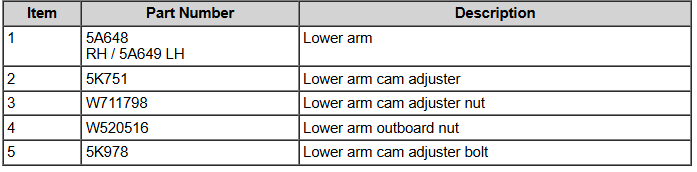
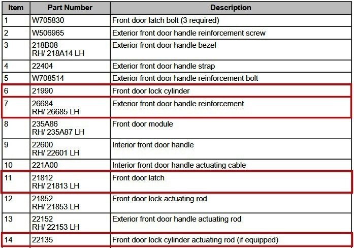
Per the sections of the 2013 Edge Workshop Manual attached below as PDF documents, and the following illustration: The door lock cylinder (item 6), mounts into the door handle reinforcement (item 7), and a D-slot in the back of the door lock cylinder engages with the D-shaped end of the door lock cylinder actuating rod (item 14), which translates the door lock cylinder rotation into a lock/unlock effect in the door latch (item 11)... Only the door lock cylinder (item 6) is removable from the door's exterior, allowing inspection of the door lock cylinder's D-slot rotation, and, the position & condition of the D-shaped end of the door lock actuating rod (item 14). If these items appear good, then removing the interior door panel will be necessary to assess the other components. The following YouTube video provides a beginning-to-end glimpse of what may be involved in that subsequent inspection... Good luck! Exterior Door Handle - Removal and Installation - 2013 Edge Workshop Manual.pdf Door Lock Cylinder - Removal and Installation - 2013 Edge Workshop Manual.pdf Front Door Handles, Locks and Latches — Exploded View - Removal and Installation - 2013 Edge Workshop Manual.pdf Front Door Latch - Removal and Installation - 2013 Edge Workshop Manual.pdf Door Handle Reinforcement - Removal and Installation - 2013 Edge Workshop Manual.pdf
-
@Bunky: Thanks for the heads-up and I apologize for the confusion! I've circled back, and I do not find this Special Service Message cross-referenced as applying to 2021-2025 Edge/Nautilus. My further cross-checking indicates SSM 53350 applies to F-150, Maverick, Mustang, Mustang Mach-E, and Transit. Why they didn't spell-out this short of an affected-models listing, I'll never know. I will cross-reference future "Various Vehicles" announcements to avoid similar occurrences. Once again, gratitude for the heads-up!
-
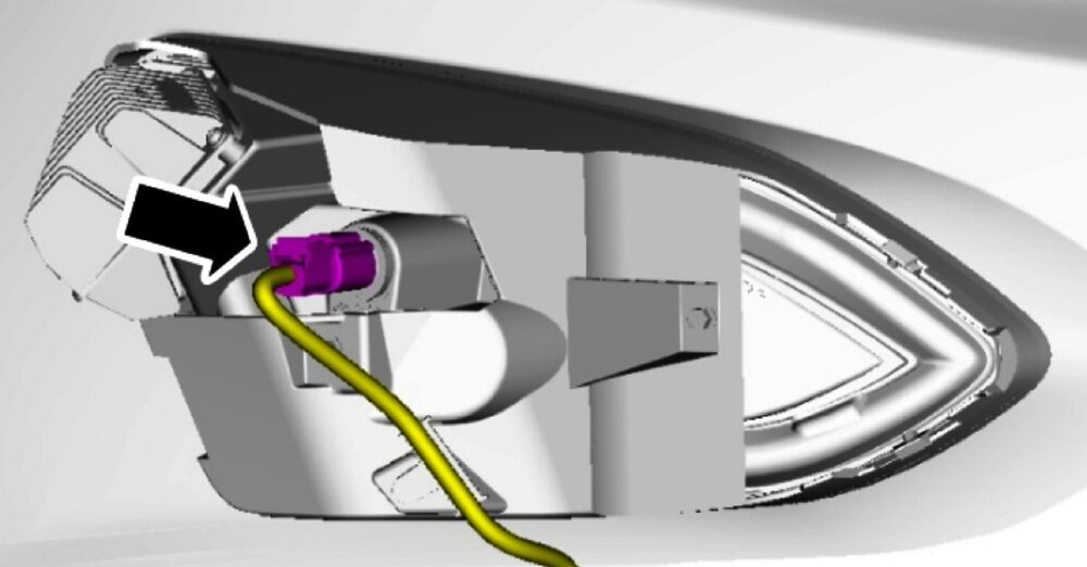
The Workshop Manual provides an aiming procedure for headlamps, but offers no aiming procedure for fog lamps. The following Workshop Manual illustration of the fog lamp housing depicts the fog lamp bulb's location, but it's not absolutely clear if this directly coincides with the location of feature you've highlighted above... If it is the same location, then the presumed hex-socketed adjustment screw may actually be a removable plug intended to prevent debris from entering the fog lamp housing prior to installation of the fog lamp bulb. Closer detail of the above-illustrated fog lamp electrical connector is shown in this photo... Workshop Manual procedures relating to removal and installation of the front bumper cover and the fog lamp assembly are attached below as PDF documents... Good luck! Front Fog Lamp - Removal and Installation - 2024 Edge Workshop Manual.pdf Front Bumper Cover - Removal and Installation - 2024 Edge Workshop Manual.pdf

-
My further cross-checking indicates SSM 53530 applies to F-150, Maverick, Mustang, Mustang Mach-E, and Transit. SSM 53530 - 2021-2025 Various Vehicles - Heated/Cooled Seats, Heated Steering Wheel And/Or Front/Rear Defrost Inoperative After Remote Start Event Some 2021-2025 Ford vehicles may exhibit a condition where heated/cooled seats, heated steering wheel and/or front/rear defrost features will not turn on after a remote start is performed through the FordPass application or the key fob. These features then operate normally when commanded in the center display screen. This may be due to the customer not setting up their "Climate Settings" through the FordPass mobile application. To correct this condition, inform the customer they should perform a remote start from FordPass and then adjust the "Climate Settings" in the FordPass application as desired. These settings only need to be set once and will persist through subsequent remote starts. Heated and cooled seats will be set to Level 2 when turned ON via "Climate Settings" in FordPass during a remote start event. This is normal operating characteristic. This condition does not affect vehicle durability and no additional diagnosis or service is required for this condition at this time.
-
Welcome @Clint in Kan! Have you had the battery load-tested to ensure it is not failing or in a failed state? Per the Workshop Manual section attached below as a PDF document, while our vehicles employ load shedding strategies to conserve power during reduced battery state-of-charge conditions, a failing or failed battery can cause modules and their related components to behave in unexpected ways. Given that the symptoms you describe materialized in a single day, particularly involving the Instrument Panel Cluster (IPC), you may want to have the battery tested, even if it has been replaced within the last few months. Good luck! Charging System - 2.0L EcoBoost - System Operation and Component Description - 2015 Edge Workshop Manual.pdf
- 11 replies
-
- 2
-
-
- body control module
- bcm
- (and 1 more)
-
Image showing installed Console Mat... Good luck!
-
Your Edge's Window Sticker is attached below as a PDF document (as it also was in my previous post)... Good luck! 2FMPK4K95PBA29008 - Window Sticker.pdf
-
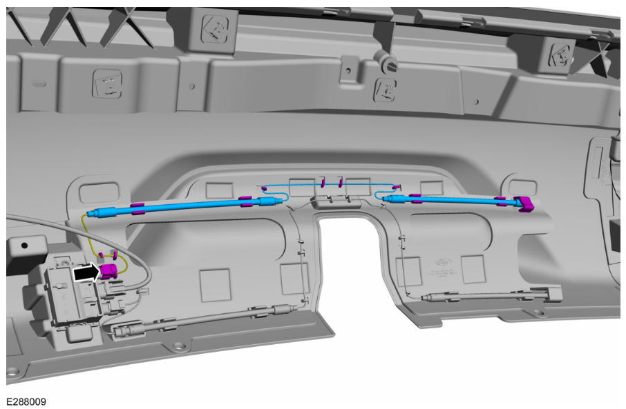
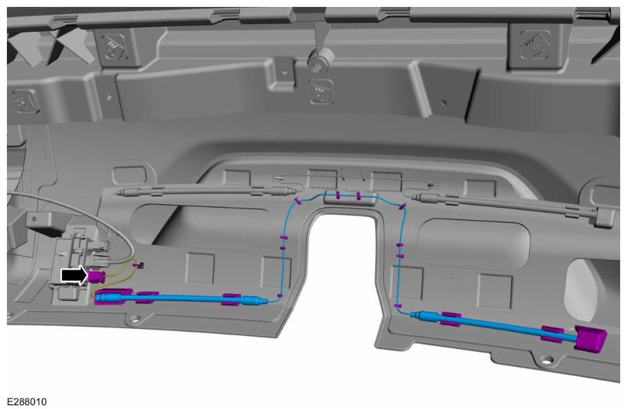
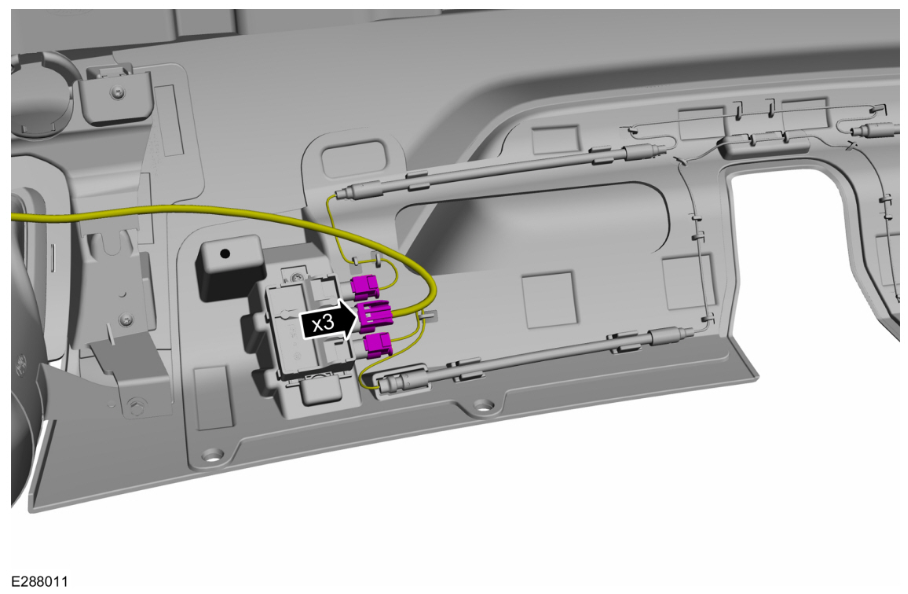
Welcome to the Forum @m4rioo! Your Edge's Window Sticker shows the vehicle is Hands-Free equipped... Per @dabangsta's comment, take a look inside your Edge's rear bumper cover for the upper & lower Hands-Free Actuator Sensors... ...and ensure that the Actuator Sensors' electrical connectors are plugged into the Hands-Free Actuator Module... Please Note: The above illustrations are of a tow package-equipped Edge bumper cover. The upper & lower Hands-Free Actuator Sensors on your Edge will be one-piece, and not split ln two-pieces with an interconnecting wire like those shown above. Good luck! 2FMPK4K95PBA29008 - Window Sticker.pdf
showsHands-FreeEquipped.thumb.jpg.96eb2550bdd57c688c3d3437da90def0.jpg)
-
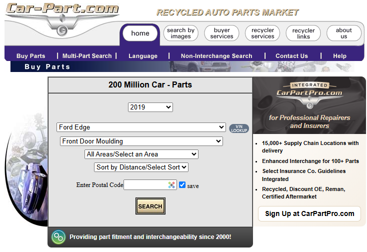
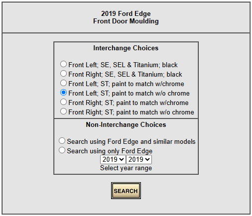
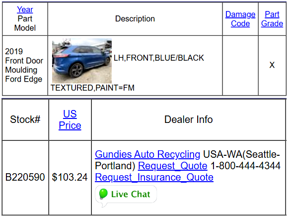
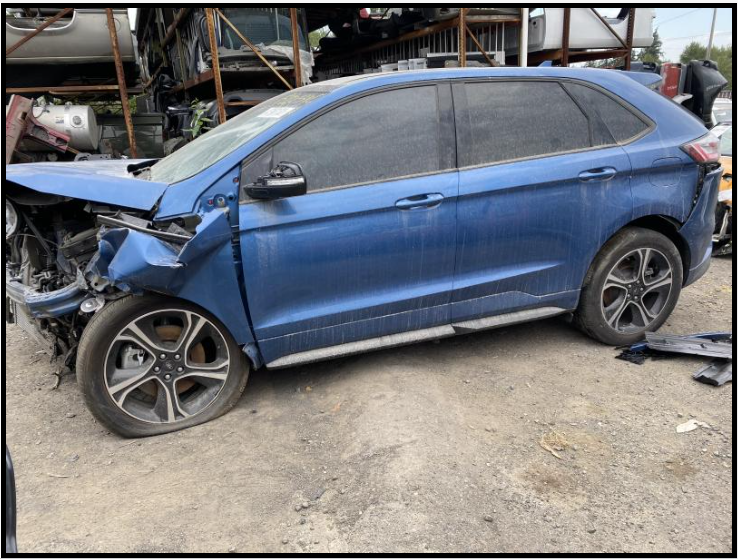
Welcome to the Forum @Huntk420! Surprisingly rare -- the only one -- via online Salvage Yard search engine Car-Part.com... 2019 Edge ST Paint Color: Ford Performance Blue Paint Code: FM Build Date: 10/19/2018 Link - Gundie's Auto Recyclers Link - Vehicle Images Good luck!
-
2024 Edge rattle noise from rear cargo trim panel
Haz replied to lasseventies's topic in 2.0L EcoBoost
@STBEAST: From the 2022-2024 Edge Workshop Manual... Good luck! Loadspace Trim Panel - Removal and Installation - 2022-2024 Edge Workshop Manual.pdf -
Excessive smoke on cold start - 2017 Ford Edge Sport 2.7l
Haz replied to JohnR0983's topic in 2.7L EcoBoost
Relevant sections from the 2017 Edge Workshop Manual are attached below as PDF documents... Good luck! Turbocharger Oil Supply Tube LH - Removal and Installation - 2.7L EcoBoost - 2017 Edge Workshop Manual.pdf Generator - Removal and Installation - 2.7L EcoBoost - 2017 Edge Workshop Manual.pdf Air Conditioning (A-C) Compressor - Removal and Installation - 2.7L EcoBoost - 2017 Edge Workshop Manual.pdf Air Conditioning (A-C) System Recovery, Evacuation and Charging - Overview of General Procedures - 2017 Edge Workshop Manual.pdf Catalytic Converter LH - Removal and Installation - 2.7L EcoBoost - 2017 Edge Workshop Manual.pdf Exhaust Flexible Pipe - Removal and Installation - 2.7L EcoBoost - 2017 Edge Workshop Manual.pdf Specifications - 2.7L EcoBoost - 2017 Edge Workshop Manual.pdf Turbocharger Oil Return Tube LH - Removal and Installation - 2.7L EcoBoost - 2017 Edge Workshop Manual.pdf Turbocharger Oil Return Tube RH - Removal and Installation - 2.7L EcoBoost - 2017 Edge Workshop Manual.pdf Turbocharger Oil Supply Tube RH - Removal and Installation - 2.7L EcoBoost - 2017 F-150 Workshop Manual.pdf Air Cleaner Outlet Pipe RH - Removal and Installation - 2.7L EcoBoost - 2017 Edge Workshop Manual.pdf -
Excessive smoke on cold start - 2017 Ford Edge Sport 2.7l
Haz replied to JohnR0983's topic in 2.7L EcoBoost
From the 2017 Edge Workshop Manual... Pinpoint Tests PINPOINT TEST A: BLUE SMOKE FROM EXHAUST Introduction Possible Causes Oil leak Air cleaner Air intake Crankcase ventilation system Internal engine damage Turbocharger A1 CHECK THE EXHAUST Start the engine. Monitor the exhaust system. Is blue smoke noticeable from the exhaust system? Yes GO to A2 No INSPECT for external oil leaks. REFER to 303-00 Engine System, Oil Leak Inspection for the engine being diagnosed. A2 CHECK THE AIR CLEANER Inspect the air cleaner. Is the air cleaner clogged? Yes REPLACE the air cleaner. REFER to 303-12 Intake Air Distribution and Filtering for the engine being diagnosed. CHECK the system for normal operation. No GO to A3 A3 CHECK THE AIR INTAKE PIPES AND HOSES Inspect the air intake pipes and hoses for loose connections or leaks. Were any loose connections or leaks found from the air intake pipes or hoses? Yes REPAIR or REPLACE the intake air system. REFER to 303-12 Intake Air Distribution and Filtering for the procedure. No GO to A4 A4 CHECK THE CRANKCASE VENTILATION SYSTEM Check the crankcase ventilation system for damage and correct operation. Refer to 303-08 Engine Emission Control, Diagnosis and Testing for the engine being diagnosed. Is the crankcase ventilation system damaged? Yes CLEAN, REPAIR or REPLACE the crankcase ventilation components. REFER to section 303-08 Engine Emission Control for the procedure. No GO to A5 A5 CHECK THE AIR INTAKE PIPES AND HOSES FOR EXCESSIVE OIL NOTE: It is normal for a small amount of combustion gas to pass into the crankcase. This gas is scavenged into the air intake system through the positive crankcase ventilation system, which incorporates a crankcase vent oil separator. Some engine oil, in the form of a vapor, is carried into the air intake system with the blow-by gases (this engine oil also contributes to valve seat durability). This means that oil will collect inside the air intake components and the turbocharger. This is not an indication that the turbocharger oil seal has failed. The turbocharger oil seal will generally not fail unless the bearings fail first, which will cause the turbocharger to become noisy or seize. Do not install a new turbocharger due to oil inside the intake. Inspect the inside of the air intake pipes and hoses for excessive oil. Is excessive oil noticeable? Yes GO to A6 No DIAGNOSE internal engine damage. REFER to 303-00 Engine System, Diagnosis and Testing for the engine being diagnosed. FOLLOW the pinpoint test to diagnose blue smoke. A6 CHECK THE TURBOCHARGER Remove the air cleaner outlet pipe and CAC intake pipe. Refer to 303-12 Intake Air Distribution and Filtering for the procedure. Inspect the compressor wheel for damage. Check that the turbine shaft spins free. Check for contact marks between the compressor wheel and the housing. Is the turbocharger damaged? Yes INSTALL a new turbocharger. REFER to 303-04 Fuel Charging and Controls - Turbocharger for the procedure. No Diagnose internal engine damage. REFER to 303-00 Engine System, Diagnosis and Testing for the engine being diagnosed. FOLLOW the pinpoint test to diagnose blue smoke. Good luck! Engine Fuel Charging and Controls - 2.7L EcoBoost - Diagnostic Pinpoint Test A - 2017 Edge Workshop Manual.pdf Positive Crankcase Ventilation (PCV) Valve - Removal and Installation - 2.7L EcoBoost - 2017 F-150 Workshop Manual.pdf-Black-Blue-WhiteSmoke-2017EdgeWorkshopManual.jpg.bac7e83c5e357cb65f4860609cf1c867.jpg)
-
Link to moulding clips sold by Advance Auto Parts Link to Advance Auto Parts store locator Good luck!
-
@STBEAST: 2024 Ford Edge Owner's Manual (PDF direct download link) Good luck!

-
@Wubster100: RF Keypad information, attached below as PDF documents... Good luck! Wireless RF Key Pad Instructions - 2020-Current Model Year - Ford Accessories.pdf Wireless RF Key Pad Quickstart Guide - August 2024 - Ford Accessories.pdf Wireless RF Key Pad Diagnosis - April 2022 - Ford Accessories.pdf


showsHands-FreeEquipped.jpg.20ee43947fa8178469b152ba66105cfd.jpg)