Haz
-
Posts
1,477 -
Joined
-
Last visited
-
Days Won
395
Content Type
Profiles
Forums
Gallery
Everything posted by Haz
-
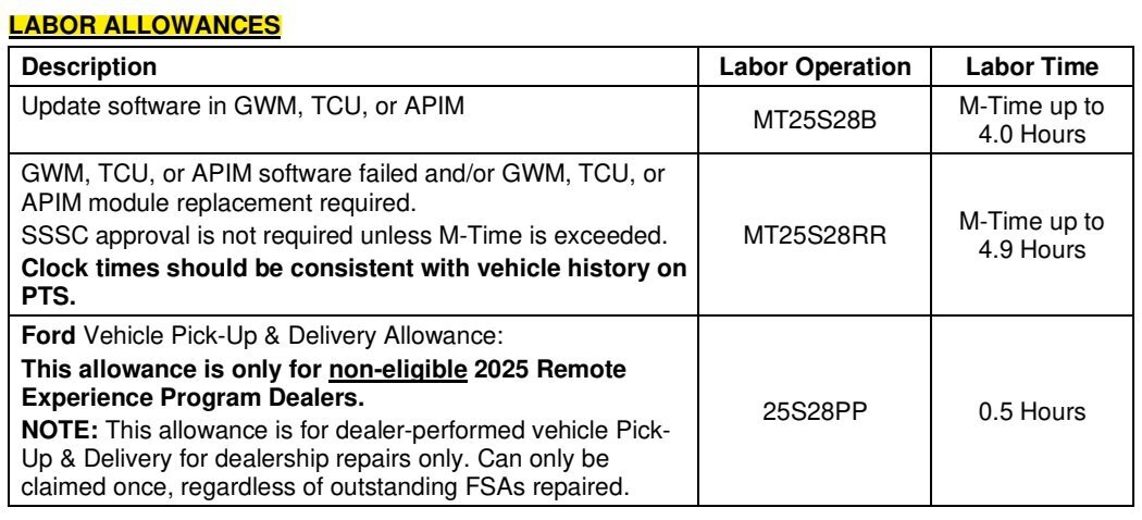
SSM 53653 2024-2025 Nautilus - Temporary Diagnostic Trouble Code (DTC) U2404 After Programming The Gateway Module (GWM) Some 2024-2025 Nautilus vehicles may exhibit a temporary U2404 DTC after programming the gateway module (GWM). This DTC will clear itself after 10 minutes of ignition off time. Additional programming or module replacement will not resolve the condition. If the DTC is still present after 10 minutes, diagnose using normal Workshop Manual (WSM) diagnostics.
-
@DBEDGE23: The 2016 2.7L EcoBoost Workshop Manual documents attached immediately-above also apply to your 2015 2.7L EcoBoost Edge Sport. Ford Service Time Labor Standard - 2015 Edge AWD Gasket Set or Oil Pan (In Chassis) (6675/ 6710/ 6781) - Remove and Install or Replace - 2.7L EcoBoost = 3.1 hours Includes clean internally mounted oil pump pick-up tube and screen and replace oil filter when directed by workshop manual. Good luck!
-
Odd Electronic Behavior (Proximity Sensors and Door Locks)
Haz replied to DNBush's topic in 2019-Current Edge & Nautilius
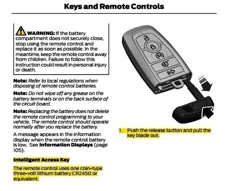
@DNBush: From the 2020 Edge Workshop Manual... Placing your device cursor over underlined acronyms may yield popup full-words descriptions of the acronyms. Switch Inhibit Feature The switch inhibit feature prevents unauthorized access to the vehicle from the door lock control switches or the liftgate release switch. The BCM disables the function of both door lock control switches and the interior liftgate release switch 20 seconds after the vehicle is electronically locked. If any of these switches are activated while they are inhibited, a chime sounds and a message is displayed in the message center to indicate the switches are inhibited. The BCM enables the function of these switches when the vehicle is electronically unlocked. This feature can be configured on/off through the message center. Passive Entry (if equipped) NOTE: To perform an accurate diagnosis of a concern, make sure the vehicle has a fully charged 12V battery and is in good condition when performing any electrical pinpoint tests. When the vehicle’s 12-volt battery is below a set threshold, certain features can be limited or become inoperative and lead to misdiagnosis. NOTE: Some models are not equipped with the passive entry feature, but are equipped with push button start. The passive entry feature unlocks or locks the doors or opens the liftgate without having to use a mechanical key blade or the RKE transmitter feature. When the BCM detects a lock or unlock sensor is touched on an exterior door handle, or the exterior liftgate release button is pressed, it activates the low frequency antenna in the corresponding exterior door handle or inside the luggage compartment area. The low frequency antenna sends out a signal to activate the passive key. The passive key then responds by sending a high frequency signal back to the RTM . The RTM interprets the high frequency signal from the passive key and sends the information to the BCM . If the BCM detects a valid programmed passive key, the BCM unlocks the driver door, unlocks or locks all 4 doors, releases the liftgate latch (manual liftgate) or sends a command to the RGTM to power open the liftgate (power liftgate). The passive entry (Intelligent Access) feature is part of vehicle load shed strategy. Door Passive Entry With a programmed passive key within 1 m (3.28 ft) outside a door, touch the lock or unlock sensor on the exterior door handle. The doors lock or unlock depending upon which sensor was touched on the handle. The unlock button is located on the inside of the handle and the lock button is located on the outside top face of the handle. The driver front door passive entry feature either unlocks the driver door (if 2-stage unlock is enabled) or all four doors (if 2-stage unlock is disabled). The passive entry feature always locks all four doors when the lock button is touched. The remaining doors passive entry feature always locks or unlocks all four doors. Some vehicles with the SE option may not be equipped with the rear doors passive entry feature. Because the door handle touch symptom is intermittent -- if you have not already -- you may want to try putting a new battery in your Intelligent Access Key... Good luck! Handles, Locks, Latches and Entry Systems - System Operation and Component Description - 2020 Edge Workshop Manual.pdf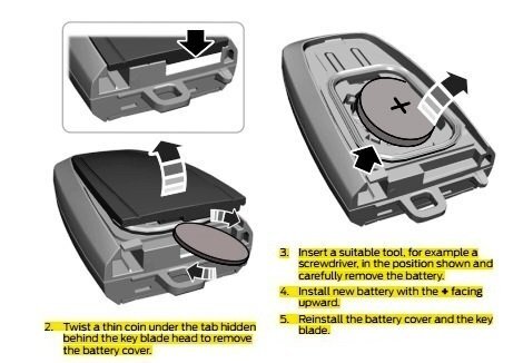
-
Welcome to the Forum @w102acd! From the 2019 Edge Workshop Manual, with emphasis added... Placing your device cursor over underlined acronyms may yield popup full-words descriptions of the acronyms. Spare Tire And Mismatched Tire Sizes Major dissimilar tire sizes between the front and rear axles could cause the AWD system to stop functioning and default to FWD or damage the AWD system. It is recommended to reinstall a repaired or replaced road tire as soon as possible. When a mismatched or tire of the wrong size is fitted, an AWD OFF message may appear in the IPC . If this condition occurs, a DTC is set and an AWD OFF message is displayed on the message center. If there is an AWD malfunction service required message in the message center from using a spare or mismatched tire, this indicator should turn off after reinstalling a tire of the same size as the normal road tire, then cycling the ignition OFF and ON. AWD Control And Fault Indicators The AWD system consists of a Power Transfer Unit (PTU), driveshaft, front and rear halfshafts, AWD module, RDU with integral RDU coupling. The systems uses the AWD module for AWD control logic. Using inputs from various modules and systems, when the power transfer unit is engaged the AWD module sends a command to the RDU which controls the amount of torque applied to the to the rear wheels. AWD system faults are indicated by a driveline icon indicator in the IPC as well as the AWD malfunction service required message in the message center. The following is Workshop Manual guidance on retrieving AWD-related Diagnostic Trouble Codes (DTCs)... Inspection and Verification NOTE: For most AWD System DTCs to set, the AWD module must detect the fault on 2 consecutive trips. 1) Record and clear DTCs from the AWD module. 2) Accelerate the vehicle from 0-45 mph with light (10%) APP. 3) Maintain 45 mph for 10 seconds. 4) Gently slow to a stop. 5) Repeat steps 2-4. 6) Accelerate the vehicle from 0-45 mph with moderate (30%) APP. 7) Maintain 45 mph for 10 seconds. 8) Gently slow to a stop. 9) Repeat steps 6-8. 10) Turn off ignition, wait 1 minute. 11) Repeat steps 2-9 or until an AWD fault message is displayed in the IPC . Whichever is sooner. 12) Retrieve continuous memory DTCs from the AWD module. If no DTCs are present, the concern may be intermittent. Do not perform a pinpoint test unless the concern is present. Good luck! Four-Wheel Drive Systems - Overview - 2019 Edge Workshop Manual.pdf Four-Wheel Drive Systems - System Operation and Component Description - 2019 Edge Workshop Manual.pdf
-
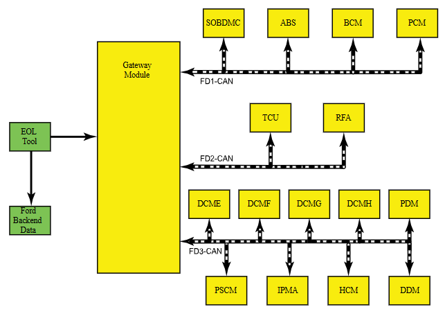
SSM 53638 - 2023-2025 Various Vehicles - Trusted Real-Time Operation Network (TRON) Module Authentication DTCs After Module Replacement - Workshop Manual Update After replacement of any TRON module, the gateway module (GWM) and the TRON capable modules can set diagnostic trouble codes (DTCs) U211A, U211B, U211C, U3034, U3035, U3036, U35D9, U35DA and/or U35DB if the secret authentication security keys are not aligned between the modules, a loss of communication is occurring between modules and/or a module is not responding. This may be a result of missing the new module secret authentication security key obtained when running the Ford Diagnosis and Repair System (FDRS) "Trusted Real-Time Operation Network (TRON) Module Authentication" procedure after replacement. When replacing a TRON capable module, run the FDRS "Trusted Real-Time Operation Network (TRON) Module Authentication" procedure to distribute a new set of secret authentication security keys to all TRON-capable modules. Using the specific VIN, refer to Workshop Manual (WSM), Section 418-00 and 418-01 for updated DTCs, applicable TRON module listings and pinpoint tests. From the 2024-2025 Nautilus Workshop Manual... Placing your device cursor over underlined acronyms may yield popup full-words descriptions of the acronyms. Trusted Real-Time Operation Network (TRON) - System Operation and Component Description System Operation Overview Trusted Real-Time Operation Network (TRON) is a cyber security protocol applied to certain modules connected to the vehicle communication networks. This protocol provides a digital message authentication for data being communicated between modules on the networks, to make sure the data received by a module is the data sent by the sending module and has not been interrupted or tampered with by an outside source. System Diagram Trusted Real-Time Operation Network (TRON) Trusted Real-Time Operation Network (TRON) secret data authentication security keys are applied to modules with motion control, safety critical and security critical functions. Not all modules on the vehicle will have data authentication security keys applied. The secret authentication security keys provide a digital data handshake between the sending module and the receiving module to confirm the data received has been sent by the expected source. The initial secret authentication security key distribution takes place at the end of the production line, prior to the vehicle release to the dealer. The key update mechanism includes a key management client and key management server modules. The key management client is the GWM and the key management server modules are the modules participating in the TRON function. The GWM generates the keys and distributes them to itself and the server modules, one module at a time sequentially. The keys are processed by the receiving modules and stored in their memory and a backup of the distributed keys is stored in the TCU . After the vehicle's TRON has been successfully configured, the production line end of line tool sends a copy to the Ford backend data systems for storage. If a TRON-capable module is replaced, the module secret authentication security key must be applied to the new module so it functions on the network when installed. When replacing a TRON capable module, run the FDRS Trusted Real-Time Operation Network (TRON) Module Authentication Diagnosis and Repair procedure to distribute a new set of secret authentication security keys to all TRON-capable modules. The GWM and the TRON capable modules can set Diagnostic Trouble Codes (DTCs) if the keys are misaligned between modules, there are communication issues on the vehicle network or a module is not responding. Component Description Gateway Module The GWM acts as the key management client for the Trusted Real-Time Operation Network (TRON) system for creating, monitoring and distributing the secret keys to the participating modules. Telematic Control Unit Module The TCU stores a backup of all Trusted Real-Time Operation Network (TRON) distributed keys.
-
Attached below as a PDF document is the Timing Belt R & I procedure for the 2.0L Duratorq-TDCi (132kW/180PS), which is identical to the procedure for the 2.0L Duratorq-TDCi (150kW/204PS)... Good luck! Timing Belt - Removal and Installation - 2.0L Duratorq-TDCi (132kW-180PS) - 2015-2022 Edge, Edge Vignale, Endura Workshop Manual.pdf Engine - Component Location - 2.0L Duratorq-TDCi - 2015-2022 Edge, Edge Vignale, Endura Workshop Manual.pdf Specifications - 2.0L Duratorq-TDCi (132kW-180PS) - 2015-2022 Edge, Edge Vignale, Endura Workshop Manual.pdf Specifications - 2.0L Duratorq-TDCi (150kW-204PS) - 2015-2022 Edge, Edge Vignale, Endura Workshop Manual.pdf
-
Ford's online United Kingdom Workshop Manual denotes its Model Year & Model coverage in this way... and its Engine coverage in this way... Attached below as PDF documents are the Timing Belt and Timing Cover workshop manual sections covering the lower-output 2.0L EcoBlue (88kW/120PS) (YN)/2.0L EcoBlue (110kW/150PS) (YM)/2.0L EcoBlue (140kW/190PS) (BC) engines... Good luck! Timing Belt - Removal and Installation - 2.0L EcoBlue (88kW-120PS) (YN) - 2.0L EcoBlue (110kW-150PS) (YM) - 2.0L EcoBlue (140kW-190PS) (BC) - 2015 - 2022 Edge, Edge Vignale, Endura Workshop Manual.pdf Timing Cover - Removal and Installation - 2.0L EcoBlue (88kW-120PS) (YN) - 2.0L EcoBlue (110kW-150PS) (YM) - 2.0L EcoBlue (140kW-190PS) (BC) - 2015 - 2022 Edge, Edge Vignale, Endura Workshop Manual.pdf


-
REAR LIFTGATE TRUNK RELEASE SWITCH-BUTTON
Haz replied to silverknight's topic in Alarms, Keyless Entry, Locks & Remote Start
Leveraging from the bottom would be best, due to the midpoint retaining tabs on either side and the locator/pivot tab at the top. Likely because of this simplicity, the GEN 1 & GEN 2 Edge/MKX/Nautilus Workshop Manuals do not provide any removal and installation procedure, though there is a electrical diagnostic Pinpoint Test covering the front & rear Power Liftgate switches, if that interests you. Good luck! -
Odd Electronic Behavior (Proximity Sensors and Door Locks)
Haz replied to DNBush's topic in 2019-Current Edge & Nautilius
@DNBush: From the 2020 Edge Workshop Manual, with emphasis added... Active Park Assist The active park assist system is a supplementary parking system that assists the operator with the task of parking in three ways: Parallel Park Assist - Detects an available parking space and automatically steers the vehicle into the space while the operator controls the accelerator, gearshift and brakes. Perpendicular Park Assist - Detects an available parking space and automatically steers the vehicle into the space while the operator controls the accelerator, gearshift and brakes. Park Out Assist (only for exiting parallel spots) - Analyzes the parking space currently occupied by the vehicle and automatically steers the vehicle out of the space while the operator controls the accelerator, gearshift and brakes. Good luck! -
REAR LIFTGATE TRUNK RELEASE SWITCH-BUTTON
Haz replied to silverknight's topic in Alarms, Keyless Entry, Locks & Remote Start
@silverknight: Our 2015 (GEN 1) MKX's Power Liftgate Rear Control Switch... Good luck!
-
REAR LIFTGATE TRUNK RELEASE SWITCH-BUTTON
Haz replied to silverknight's topic in Alarms, Keyless Entry, Locks & Remote Start
Representative sections from the 2014 Edge Workshop Manual and Wiring Resource are attached below as PDF documents... Good luck! Liftgate Trim Panel - Removal and Installation - 2014 Edge Workshop Manual.pdf Liftgate Release Switch - Removal and Installation - 2014 Edge Workshop Manual.pdf LIFTGATE RELEASE SWITCH - Connector C4216 Pinout Diagram - 2014 Edge.pdf LIFTGATE RELEASE SWITCH - Connector C4216 Location - 2014 Edge.pdf -
The following information from the 2011 Edge Workshop Manual and Wiring Resource -- below and attached as PDF documents -- may be helpful if your efforts progress from inquiry to adaptive installation... Placing your device cursor over underlined acronyms may yield popup full-words descriptions of the acronyms. Headlamps - Principles of Operation Exterior Lighting The headlamp switch is integrated into the Front Lighting Control Module (FLM) . The FLM monitors the headlamp switch position and sends a message over the High Speed Controller Area Network (HS-CAN) to the Body Control Module (BCM) to indicate the headlamp switch status (position or a fault with the headlamp switch). If the BCM detects a fault from the headlamp switch or loses communication with the FLM , the BCM turns the parking lamps and headlamps on and keeps them on until the battery saver feature times out. If either situation occurs, the BCM cannot be ruled immediately as being at fault. This is normal behavior of the BCM design as a fault has been detected with the inputs from the headlamp switch. When the BCM receives input requesting the headlamps on, it supplies voltage to the headlamp bulbs (halogen headlamps) or the ballasts (High Intensity Discharge (HID) ) within each headlamp assembly. High Beam and Flash-to-Pass The Steering Column Control Module (SCCM) monitors the multifunction switch for a flash-to-pass or high beam request. When the multifunction switch is in the FLASH-TO-PASS or HIGH BEAM position, the SCCM sends a message to the BCM to indicate the request. When the low beams are on and the BCM receives a request for high beams (or a flash-to-pass request), the headlamps remain powered and a shutter within each headlamp is activated. This changes the headlamp beam pattern to illuminate a greater distance. When the low beams are off and the flash-to-pass is requested, the headlamps and the shutters are activated for approximately 0.5 second. When the low beams are on and the flash-to-pass is requested, the shutters within the headlamps are activated as long as the multifunction switch is held in the FLASH-TO-PASS position. Field-Effect Transistor (FET) Protection A Field-Effect Transistor (FET) is a type of transistor that, when used with module software, monitors and controls current flow on module outputs. The FET protection strategy prevents module damage in the event of excessive current flow. The BCM FET protected output circuits for the headlamp system are both low and high beam output circuits. The BCM utilizes an FET protective circuit strategy for many of its outputs. Output loads (current level) are monitored for excessive current (typically short circuits) and are shut down (turns off the voltage or ground provided by the module) when a fault event is detected. A short circuit DTC is stored at the fault event and a cumulative counter is started. When the demand for the output is no longer present, the module resets the FET protection to allow the circuit to function. The next time the driver requests a circuit to activate that has been shut down by a previous short (FET protection) and the circuit is still shorted, the FET protection shuts off the circuit again and the cumulative counter advances. When the excessive circuit load occurs often enough, the module shuts down the output until a repair procedure is carried out. Each FET protected circuit has 3 predefined levels of short circuit tolerance based on the harmful effect of each circuit fault on the FET and the ability of the FET to withstand it. A module lifetime level of fault events is established based upon the durability of the FET . If the total tolerance level is determined to be 600 fault events, the 3 predefined levels would be 200, 400 and 600 fault events. When each tolerance level is reached, the short circuit DTC that was stored on the first failure cannot be cleared by the clear the CMDTCs command. The module does not allow this code to be cleared or the circuit restored to normal operation until a successful self-test proves that the fault has been repaired. After the self-test has successfully completed (no on-demand DTCs present), DTC U1000:00 and the associated DTC (the DTC related to the shorted circuit) automatically clears and the circuit function returns. When each level is reached, the DTC associated with the short circuit sets along with DTC U1000:00. These DTCs are cleared using the module on-demand self-test, then the Clear DTC operation on the scan tool (if the on-demand test shows the fault corrected). The module never resets the fault event counter to zero and continues to advance the fault event counter as short circuit fault events occur. If the number of short circuit fault events reach the third level, then DTCs U1000:00 and U3000:49 set along with the associated short circuit DTC . DTC U3000:49 cannot be cleared and the BCM module must be replaced after the repair. Good luck! Headlamp Assembly - Removal and Installation - 2011 Edge Workshop Manual.pdf Bumper — Exploded View, Front - Removal and Installation - 2011 Edge Workshop Manual.pdf Bumper Cover — Front - Removal and Installation - 2011 Edge Workshop Manual.pdf Halogen Headlamps - Wiring Diagram - 2011 Edge.pdf High Intensity Discharge (HID) Headlamps - Wiring Diagram - 2011 Edge.pdf HEADLAMP, LEFT - Connector C1021A Pinout Diagram - 2011 Edge.pdf HEADLAMP, RIGHT - Connector C1041A Pinout Diagram - 2011 Edge.pdf HEADLAMP, RIGHT - Connector C1041A Location Illustration - 2011 Edge.pdf HEADLAMP, LEFT - Connector C1021A Location Illustration - 2011 Edge.pdf
- 1 reply
-
- 1
-

-
@dolsen: If you have not already, you may want to review this past discussion that included Glare Free Headlamps... Good luck!
-
Welcome to the Forum @RLA! Per the relevant sections of the 2017 Edge Workshop attached below as PDF documents, you are correct -- the Bumper Cover must be removed... Good luck! Front Fog Lamp - Removal and Installation - 2017 Edge Workshop Manual.pdf Front Bumper Cover - Removal and Installation - 2017 Edge Workshop Manual.pdf
- 1 reply
-
- 2
-

-
-
SSM 53601 2020-2023 Explorer/Aviator, 2020-2025 Police Interceptor Utility, 2020-2025 Escape/Corsair, 2022-2025 Maverick, 2024-2025 Nautilus - Hybrid - Illuminated MIL With DTC P2450:00 Stored In The PCM Some 2020-2023 Explorer/Aviator, 2020-2025 Police Interceptor Utility, 2020-2025 Escape/Corsair, 2022-2025 Maverick, and 2024-2025 Nautilus vehicles equipped with a hybrid powertrain may exhibit an illuminated malfunction indicator lamp (MIL) with diagnostic trouble code (DTC) P2450:00 stored in the powertrain control module (PCM). This may be due to an evaporative emission system concern or may also be caused by the customer overfilling the fuel tank. If this condition occurs, perform normal diagnosis per Workshop Manual (WSM) Section, 303-13 and repair as necessary. Inform the customer that the condition may have been caused by overfilling of the fuel tank and to not top-off the fuel tank when the fuel pump nozzle automatically shuts off for the first time. Refer the customer to the Fuel and Refueling section of their Owner Manual for additional information.
-
Oil Filter Inspection Special Tool(s) / General Equipment Oil Drain Equipment Knife Vise Activation Remove the oil filter. Refer to oil change. Drain any excess oil from the oil filter. Use the General Equipment: Oil Drain Equipment Using an oil filter cutter, cut the housing from the baseplate. Remove the support tube and oil filter element assembly from the housing. Separate the oil filter element from the support tube. Use the General Equipment: Knife Use the General Equipment: Vise Twist the top and bottom endcaps and separate the top or bottom endcaps from the support tube. Inspect the support tube for debris. Check for metal debris, fine or course, that would indicate a catastrophic failure of the engine. Expand the oil filter element. Normal element, a few particles of metal is normal. Bearing damage, large amount of bearing metal is not normal. If the oil filter inspection shows excessive metal debris to indicate catastrophic failure of the engine, REMOVE the engine oil pan and inspect the main and connecting rod bearings for damage. DISASSEMBLE the engine to determine the extent or source of the damage. REFER to Engine Oil Pan. REFER to Removal. REFER to Bearing Inspection. REFER to Engine Disassembly. © Copyright 2025, Ford Motor Company. Oil Filter Inspection - Workshop Manual General Procedure.pdf
-
Once again, perhaps unnecessary due to your replacement of the Master Cylinder, but with emphasis below, and additional PDF Workshop Manual sections... Brake Master Cylinder Compensator Ports The purpose of the compensator ports in the brake master cylinder is to supply additional brake fluid from the master cylinder reservoir when needed by the brake system due to brake lining wear and allow brake fluid to return to the master cylinder reservoir when the brakes are released. The returning brake fluid creates a slight turbulence in the master cylinder reservoir. This is a normal condition and indicates that the compensator ports are not clogged. Clogged compensator ports may cause the brakes to hang up or not fully release. Good luck! Brake System - Principles of Operation - 2013 Edge Workshop Manual.pdf Front Disc Brake - Specifications - 2013 Edge Workshop Manual.pdf Brake Caliper - Removal and Installation - 2013 Edge Workshop Manual.pdf Component Bleeding - General Procedures - 2013 Edge Workshop Manual.pdf Brake System Bleeding - General Procedures - 2013 Edge Workshop Manual.pdf
-
@sounduser: Your question may be addressed by the U.K. edition Workshop Manual sections attached below as PDF documents... Please note that I selected 177kW/240PS EcoBlue information -- if you require the lower output EcoBlue information, just let me know and I will provide it. Good luck! Engine - System Operation and Component Description - 2.0L EcoBlue Diesel - 2015-2022 Edge, Edge Vignale, Endura Workshop Manual.pdf Engine Component Location - Description and Operation - 2.0L EcoBlue Diesel - 2015-2022 Edge, Edge Vignale, Endura Workshop Manual.pdf Timing Belt - Removal and Installation - 2.0L EcoBlue Diesel - 2015-2022 Edge, Edge Vignale, Endura Workshop Manual.pdf Timing Belt Cover - Removal and Installation - 2.0L EcoBlue Diesel - 2015-2022 Edge, Edge Vignale, Endura Workshop Manual.pdf
-
Welcome to the Forum @Todd Turner! Your described repair efforts indicate this question may be unnecessary, but since you don't mention performing a Programmable Module Installation (PMI) procedure: When the ABS Module was replaced, did you configure the new ABS Module using the As-Built values contained in the ABS Module you removed? Also, when the brake lock-up symptom occurs, are you hearing the ABS pump activating? Relevant sections from the 2013 Edge Workshop Manual and Wiring Resource are attached below as PDF documents... Good Luck! Brake Pedal and Bracket - Removal and Installation - 2013 Edge Workshop Manual.pdf BRAKE PEDAL POSITION (BPP) SWITCH - Connector C2064 Pinout Diagram - 2013 Edge.pdf BRAKE PEDAL POSITION (BPP) SWITCH - Connector C2064 Location - 2013 Edge.pdf BRAKE PEDAL POSITION (BPP) SWITCH - Power Distribution Wiring Diagram - 2013 Edge.pdf Stoplamp Switch - Removal and Installation - 2013 Edge Workshop Manual.pdf Component Tests - Brke System Diagnosis and Testing - 2013 Edge Workshop Manual.pdf Hydraulic Control Unit (HCU) - Removal and Installation - 2013 Edge Workshop Manual.pdf Pinpoint Test C - DTCs C0044.28, C0044.49 and C0044.64 - Diagnosis and Testing - 2013 Edge Workshop Manual.pdf Wheel Speed Sensor — Front - Removal and Installation - 2013 Edge Workshop Manual.pdf
-
Historical references attached below as PDF documents... Good luck! Customer Satisfaction Program 19N09 - Left Front Door Latch Extended Coverage - 12-12-2019 - Dealer Bulletin.pdf Customer Satisfaction Program 19N09 - Left Front Door Latch Extended Coverage - 12-12-2019 - Technical Instructions.pdf TSB 18-2013 - Door Ajar Lamp Remains Illuminated When Doors Closed.pdf
-
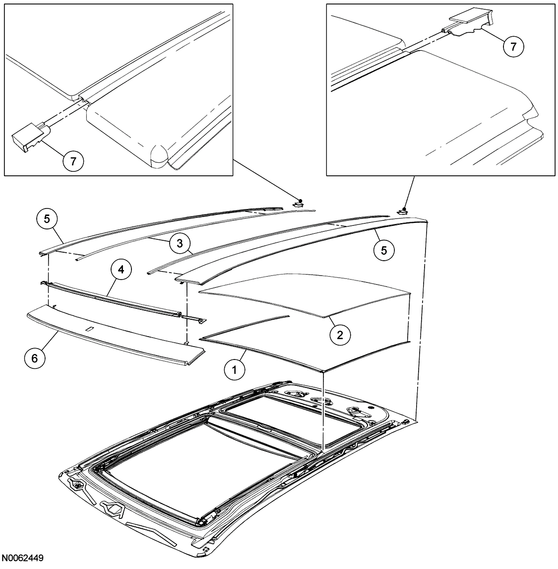
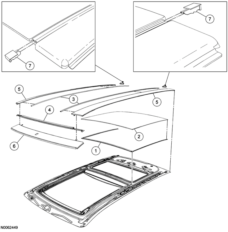
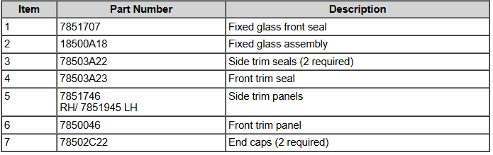
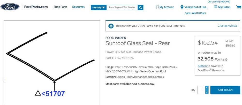
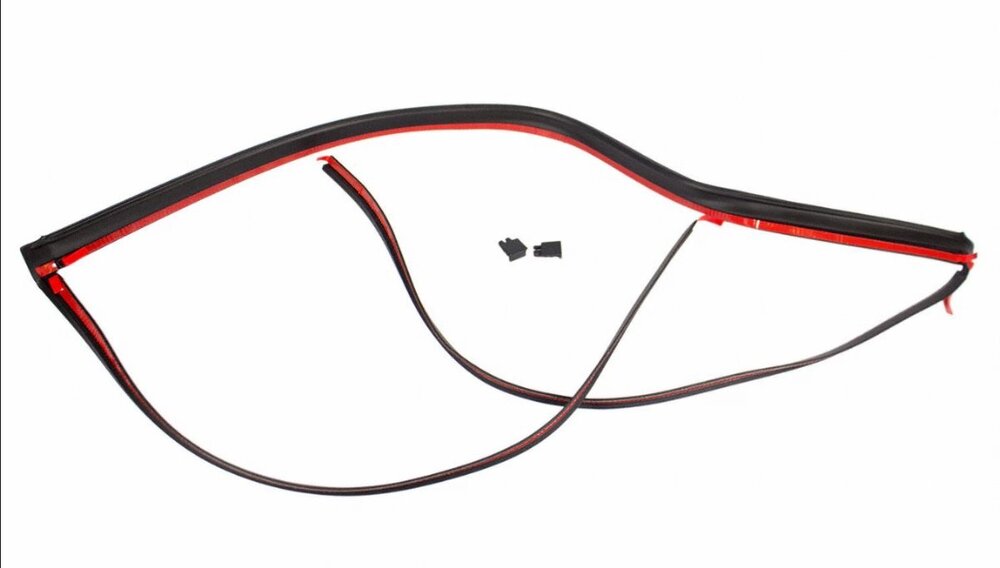
@edgemaster: The 2009 Edge Workshop Manual provides the following illustration showing the Fixed Glass panel of your Edge's Panoramic Roof. You are describing the U-shaped Fixed Glass Front Seal (item 1), which along with the two Side Trim Seals (item 3) fill the gaps at the front and on the left & right sides of the Fixed Glass panel, where channels exist to drain water to the rear of the roof, where it flows out through the left & right side End Caps (item 7)... As you may already know, the waterproof sealing of the Fixed Glass panel is provided by a continual bead of urethane adhesive applied to the metal roof structure in the shape of Path 1 or Path 2, depending upon the model year of the Edge/MKX... Ford's parts-selling website offers photos of the Front seal which may be helpful, and which appears to show the red pull-off strip for double-sided tape used to affix the Front seal to the roof, underneath the outer edges of the Fixed Glass panel... Link to this FordParts webpage The Workshop Manual does not provide any procedure relating to removal and installation of the Front seal. If it did, I expect because of the minimal clearance between the Front seal's left-hand & right-hand side legs and the seals on the Side Trim pieces, the procedure might involve removal of the Fixed Glass panel by cutting the bead of urethane sealant, cleaning residue from the glass panel and the metal roof, then installing of the Front seal on the roof, apply the continuous bead of urethane sealant, and install the Fixed Glass panel, all of which would very likely involve a professional glass installer. Working clearances between the rear of the Moving Glass panel and the front of the Fixed Glass panel are greater, however, so if the Front seal is only deteriorated on the front, then it might be possible to cut the existing Front seal away from its side legs, and similarly cut the replacement Front seal after clearing away all remaining rubber from underneath the front edge of the Fixed Glass panel. I would say, before attempting any of this, it would be prudent to use a feeler gage to assess how much clearance or compression-on-the-seal exists between the bottom of the glass panel and the metal rooftop. If the double-sided-taped seal cannot be freely inserted and affixed underneath the front edge of the Fixed Glass panel, then I expect, services of a professional glass installer may be needed - at a much higher cost. Good luck! Roof Opening Panel Glass — Rear Fixed - Removal and Installation - 2009 Edge Workshop Manual.pdf Roof Opening Panel — Exploded View Illustrations - 2009 Edge Workshop Manual.pdf


-
2011 Ford Edge Rear Suspension Torque Specs Needed
Haz replied to mdk1016's topic in Brakes, Chassis & Suspension
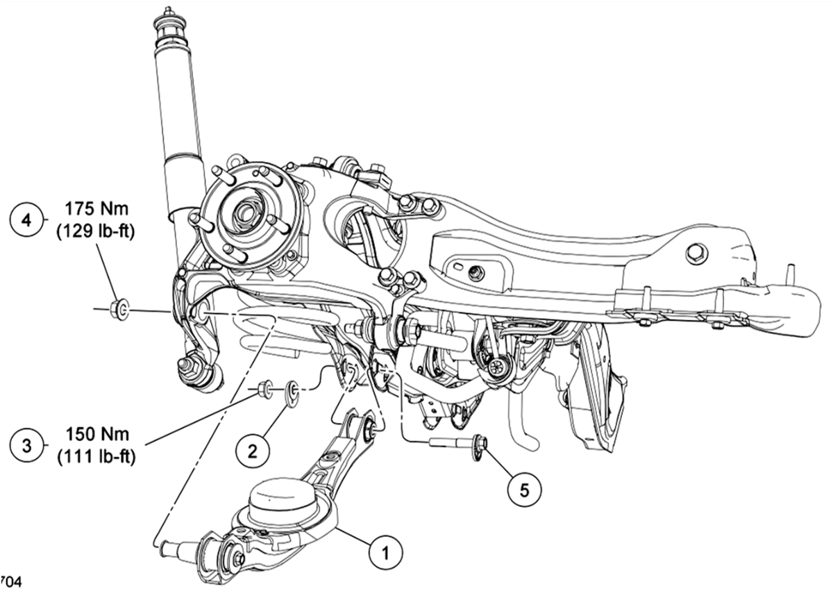
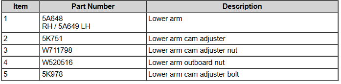
Lower Arm illustration and guidance from the Workshop Manual... NOTICE: Suspension fasteners affect performance of vital components and systems and their failure may result in major service expense. If replacement is necessary install new parts with the same part numbers or equivalent part. Do not use a replacement part of lesser quality or substitute design. Tighten the fasteners to specification during reassembly. NOTICE: Tighten the suspension bushing fasteners with the weight of the vehicle resting on the wheels and tires or incorrect clamp load and bushing damage may occur. Good luck!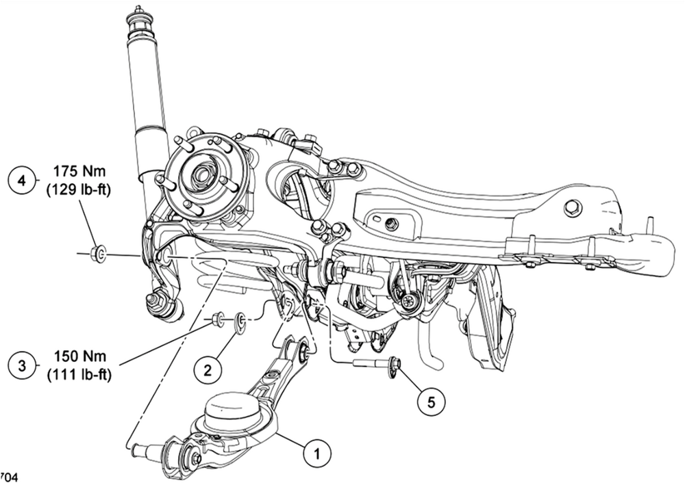
-
2011 Ford Edge Rear Suspension Torque Specs Needed
Haz replied to mdk1016's topic in Brakes, Chassis & Suspension
Welcome to the Forum @mdk1016! From the 2011 Edge Workshop Manual... Rear Suspension Torque Specifications Description Nm lb-ft lb-in Lower arm cam adjuster nut 150 111 — Lower arm outboard nut 175 129 — Parking brake cable bolt 18 — 159 Shock absorber lower nut 225 166 — Shock absorber upper nut 25 18 — Stabilizer bar bracket nut 55 41 — Stabilizer bar link upper and lower nut 40 30 — Toe link inboard nut 200 148 — Toe link outboard nut 175 129 — Upper arm inboard nut 175 129 — Upper arm outboard bolts 175 129 — Wheel hub and bearing bolt 115 85 — Wheel hub nuta — — — Trailing arm bracket-to-frame bolts 48 35 — Trailing arm nut 150 111 — Wheel knuckle-to-trailing arm nuts 103 76 — Wheel speed sensor bolt 7 — 62 Rear Drive Axle/Differential Torque Specifications Description Nm lb-ft Differential housing cover bolts 23 17 Differential housing-to-front insulator bracket bolts 90 66 Filler plug 29 21 Front insulator bracket-to-subframe bolts 90 66 Pinion flange nut 244 180 Rear driveshaft U-joint flange bolts 70 52 Side insulator bracket-to-rear axle differential bolts 90 66 AWD vehicles NOTICE: Do not tighten the rear wheel hub nut with the vehicle on the ground. Tighten the wheel hub nut to specification before the vehicle is lowered to the ground. Wheel bearing damage occurs if the wheel bearing is loaded with the weight of the vehicle applied. NOTE: Apply the brake to keep the halfshaft from rotating. Position the halfshaft in the wheel hub and bearing assembly and use the previously removed wheel hub nut to seat the halfshaft. Tighten to 350 Nm (258 lb-ft). Remove and discard the wheel hub nut. NOTICE: Install and tighten the new wheel hub nut to specification within 5 minutes of starting it on the threads. Always install a new wheel hub nut after loosening, or when not tightening within the specified time, or damage to the components may occur. Install a new wheel hub nut. Tighten to 350 Nm (258 lb-ft). Good luck!