-
Posts
11,144 -
Joined
-
Last visited
-
Days Won
269
Content Type
Profiles
Forums
Gallery
Everything posted by WWWPerfA_ZN0W
-
Windshield seal strip or antenna base seal are likely culprits. If you have access to a water tap/hose, you can test this yourself.
-
Hopefully just low fluid. If this is the case, other fluids in the vehicle are likely also suspect - transmission, brake, coolant, etc. Attend to those as well. Here is a DIY "flush" of the power steering system
-
Welcome, congratulations, and do post pics of your new ride!
-
I would have an upholstery shop look at making it comfortable for your wife, unless you think the required changes are too much. They can look at what is comfortable for her and "make it so". I am not sure the swap can be made to happen, but here is the factory manual for gen 2 https://drive.google.com/drive/u/2/folders/1wBzOTmEZvCvnzvmTI470QBGyYX60xDBh Maybe it will work!
-
If the catalyst is empty and not catalyzing, you need new catalysts to stop the error codes from coming back. You can opt to use parts that will fake the system into believing that the cats are still functional, or programmatically turn off the error codes, but it is a far better option to replace them altogether. States like California, NY, and Maine of course make it all but impossible to use anything but OEM parts, which in turn drives up the cost quite a bit. You can try and source them from junkyards/used parts places like LKQ and car-part.com, but IDK how much they charge. And warranty is rather dismal anyway compared to when put on a brand new vehicle. https://www.rockauto.com/en/catalog/ford,2010,edge,3.5l+v6,1444714,exhaust+&+emission,catalytic+converter,5808
-

Add a Shelf To Your Center Console
WWWPerfA_ZN0W replied to Gadgetjq's topic in Accessories & Modifications
Excellent! Keep em coming -

What have you done to/with your Edge/MKX today?
WWWPerfA_ZN0W replied to WWWPerfA_ZN0W's topic in Accessories & Modifications
So sorry to hear. Sounds like you should complain to Ford when you get the survey, and never go back to this dealer. YIKES! -
Do you recall what the error code(s) was/were? The common P0420/0430 or something else? Does the engine sound normal at idle? Are there any hissing or whooshing type noises from the intake or the engine that might indicate a vacuum leak? Typically do not see burnt valves on these vehicles, but keep that in mind for a REMOTE possibility.
-
mileage on your Edge? I did not see spark plugs and coils mentioned. ever been replaced? what codes are present in the PCM, if any? has fuel pressure been checked?
-
Dunno. Hope this is the last of it for a while. 700$ is much more than I thought this job would cost.
-
Thankfully the water pumps are external on the ecoboost engines, and cheap to replace as a result. Removal and Installation Drain the cooling system. For additional information, refer to Cooling System Draining, Filling and Bleeding in this section Loosen the 3 coolant pump pulley bolts. To install, tighten to 20 Nm (177 lb-in). Rotate the accessory drive belt tensioner and detach the accessory drive belt. Make sure the accessory drive belt is positioned so coolant can not contaminate the belt. Remove the 3 bolts and the coolant pump pulley. To install, do not tighten the bolts at this time. Remove the 3 bolts, the coolant pump and the O-ring seal. Discard the O-ring seal. To install, lubricate the new O-ring seal with clean engine coolant. To install, tighten to 10 Nm (89 lb-in). To install, reverse the removal procedure. Fill and bleed the cooling system. Could be the thermostat housing as well. Thermostat Housing — 2.0L GTDI Removal and Installation NOTE: The thermostat and thermostat housing are replaced as an assembly. Drain the cooling system. Release the 2 clamps and disconnect the 2 coolant hoses. Remove the 3 bolts and the thermostat housing. Inspect the gasket and install a new gasket if necessary. To install, tighten to 10 Nm (89 lb-in).
-

09 Edge Overheating!!
WWWPerfA_ZN0W replied to sixpack.sid's topic in Interior, A.C., Heat, Interior Trim
Always keep the oem fan module for testing when using aftermarket assemblies. Sometimes, the module itself fails, but very very very often it is the fan motors that burn out. So you can likely make the aftermarket assembly work with the oem module. -
Don't know about gen 2.5, but gen 2 sport had no oil cooler (typically coolant system linked) https://drive.google.com/open?id=1jsWiisAd2B_oFRfm1X2qlGVgr3JOMBwU Transmission cooling, with and without active warmup https://drive.google.com/open?id=1dmOFQNy3taKEqH6eEI0FxczzQkNdrdqA Active transmission warm-up uses reclaimed heat energy to warm up the transmission faster. This, along with a durable, synthetic, ultra-low-viscosity fluid – engineered specifically for the new Edge – reduces component friction and helps save fuel https://media.ford.com/content/fordmedia/fna/us/en/news/2018/09/12/new-ford-edge--edge-st-use-artificial-intelligence-to-help-impro.html https://www.sae.org/publications/technical-papers/content/2018-01-0385/ An oil cooler IS mentioned for the 3.5 tho https://drive.google.com/open?id=1_aAtiuGaCEee6Mzb6euvECksoZ1e4V8Z https://www.fordpartsgiant.com/parts-list/2018-ford-edge/engine/oil_cooler_and_filter.html?Filter=(30275)&PNC=6A642
-
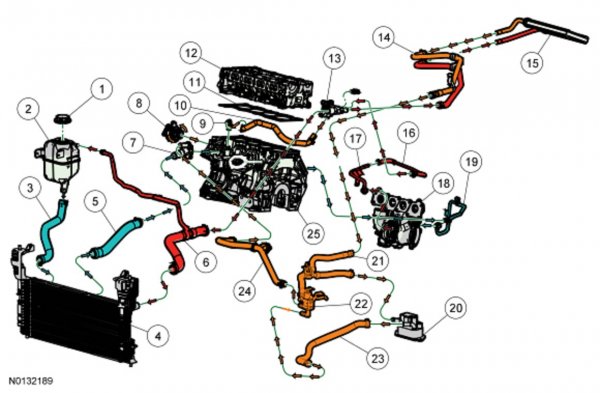
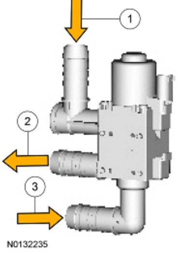
As far as the valve, this is likely what they were referring to (and probably where the leak is from due to faulty repair): Coolant Flow Diagram - 2.0L Gasoline Turbocharged Direct Injection (GTDI) Temperature Control Valve NOTE: The temperature control valve directs warm coolant to the transmission fluid cooler/warmer mounted on the transmission during transmission warm-up and allows the coolant to bypass the warmer when the transmission fluid reaches normal operating temperature. NOTE: At 38°C (100°F) ambient temperature, amber arrows indicate temperature approximately 82°C (179°F). Item Part Number Description 1 — Inlet open when energized 2 — Outlet 3 — Inlet open when de-energized Coolant Flow Diagram - 2.0L Gasoline Turbocharged Direct Injection (GTDI) NOTE: At 38°C (100°F) ambient temperature, green arrows indicate temperature below 82°C (179°F), amber arrows indicate temperature approximately 82°C (179°F), red arrows indicate temperature above 82°C (179°F). Item Part Number Description 1 8101 Pressure relief cap 2 8A080 Degas bottle 3 8C289 Degas bottle-to-radiator hose 4 8005 Radiator 5 8286 Lower radiator hose 6 8260 Upper radiator hose 7 8575 Thermostat assembly 8 8501 Coolant pump 9 8597 Coolant bypass hose connector 10 8597 Coolant bypass hose 11 6051 Cylinder head gasket 12 6049 Cylinder head 13 8K556 Coolant outlet connector adapter 14 18C553 Heater hose assembly 15 18476 Heater core 16 8K153 Turbocharger coolant outlet hose 17 8592 Turbocharger coolant outlet tube 18 6K682 Turbocharger 19 8555 Turbocharger coolant inlet tube 20 7A095 Transmission fluid warmer 21 18N345 Heater hose assembly 22 18594 Temperature control valve 23 6N745 Transmission fluid warmer-to-temperature control valve coolant hose 24 18472 Heater hose 25 6010 Cylinder block
-

2012-2014 Edge GTDI Coolant Flow Diagram.jpg
WWWPerfA_ZN0W posted a gallery image in Member Photo Albums
From the album: Miscellany
-

2012-2014 Edge GTDI Coolant Temperature Control Valve.jpg
WWWPerfA_ZN0W posted a gallery image in Member Photo Albums
From the album: Miscellany
-
Hate when this happens, UGH. Miles on your Edge, history of coolant changes? Is there slime buildup in the reservoir/degas bottle (bottom half)? What coolant was in there prior to the heater core being replaced? Specialty Green, Orange, or other? What coolant did they replace it with? EDIT: BTW, while replacing the heater core IS a labor intensive job, it does not require removing the whole dash as in older MYs of other vehicles. Lots of steps tho: Heater Core And Evaporator Core Housing Removal and Installation NOTE: The O-ring seals used on this vehicle are not interchangeable with all similarly sized O-ring seals used on other Ford products. Use only the O-ring seals specified for this vehicle in the Ford master parts catalog. Recover the refrigerant. For additional information, refer to Section 412-00 . Drain the engine coolant. For additional information, refer to Section 303-03 . Remove the upper intake manifold. For additional information, refer to Section 303-01A or Section 303-01B . Remove the instrument panel. For additional information, refer to Section 501-12 . Remove the 3 driver side carpet pin-type retainers and position the driver side front carpet aside. Remove the 4 LH rear footwell duct pin-type retainers and the LH rear footwell duct. Remove the 2 passenger front carpet pin-type retainers and position the passenger front carpet aside enough to access the 2 front pin-type retainers on the RH rear footwell duct. Remove the 2 front pin-type retainers on the RH rear footwell duct and detach the RH rear footwell duct from the heater core and evaporator core housing. Release the 2 heater hose clamps at the heater core and disconnect the heater hoses. Remove the Thermostatic Expansion Valve (TXV) fitting nut and detach the A/C lines from the TXV . Discard the O-ring seals. To install, tighten to 8 Nm (71 lb-in). NOTICE: The retaining clips on the plastic evaporator drain tube elbow will break if the elbow is removed from inside the vehicle. If the evaporator drain tube elbow must be removed, the retaining clips must be detached from below the vehicle. If the plastic evaporator drain tube elbow does not need to be removed, only detach the evaporator drain tube from the elbow. Disconnect the evaporator drain tube from the elbow at the floorpan. Remove the 5 heater core and evaporator core housing nuts. To install, tighten to 8 Nm (71 lb-in). Remove the heater core and evaporator core housing. To install, reverse the removal procedure. Install new O-ring seals lubricated in clean PAG oil. Lubricate the refrigerant system with the correct amount of clean PAG oil. For additional information, refer to Section 412-00 . Fill the engine coolant level. For additional information, refer to Section 303-03 . Evacuate, leak test and charge the refrigerant system. For additional information, refer to Section 412-00 . Heater Core Removal and Installation NOTE: If a heater core leak is suspected, the heater core must be pressure leak tested before it is removed from the vehicle. For additional information, refer to Section 412-00 . Remove the heater core and evaporator core housing. For additional information, refer to Heater Core And Evaporator Core Housing in this section. Remove the 6 floor duct screws and the floor duct. Remove the heater core tube dash panel seal. Remove the heater tube bracket screw and the heater tube bracket. Remove the 5 fresh air inlet duct screws and the fresh air inlet duct. Disconnect the wire harness from the plenum chamber. Remove the 7 lower facing plenum chamber screws. Orient the heater core and evaporator core housing with the plenum chamber upright. Remove the upper facing plenum chamber screw. Remove the 2 plenum chamber clips and remove the plenum chamber being careful not to allow the evaporator core to become dislodged from the installed position. NOTICE: Do not handle the heater core by the inlet and/or outlet tube to remove. Handling the heater core by the tubes may damage the joints and lead to failure of the heater core. Remove the heater core in the following sequence. Grasp the heater core by the core-side of the heater tube connections and partially remove it from the plenum chamber. Grasp the heater core by the top of the core and remove it from the plenum chamber. NOTE: It is not necessary to carry out this step if the evaporator core has not become dislodged from the installed position during this procedure. If the evaporator core has been moved at any point during heater core removal, remove the evaporator core, verify that the drain seal is installed in the correct position and install the evaporator core in the correct position. To install, reverse the removal procedure.
-
Welcome and congrats! The general Lighting section https://www.fordedgeforum.com/forum/47-glass-lenses-lighting-mirrors-sunroof-bamr-wipers/ The Gen 2+ section (open to all topics) by MY https://www.fordedgeforum.com/forum/81-2015-edge-mkx-generation-ii/
-
You can still plead your case with Ford even if the dealer refuses to assist you. Polite but firm. Work up the chain, don't take no for an answer, not at the dealership and not at Ford. 62K miles is a ridiculous timeframe to be blowing an engine, and it is not uncommon to see this failure, btw. Hopefully, members who have gone thru this will step up and share their experiences. Otherwise you can always join up on MACT FORD EDGE on facebook, where you will be in good company. If you choose the legal option (nuclear option lol), certainly there will not be a dearth of similar incidents to prove your point.
-
Welcome, congrats, and enjoy your new ride!
-

2012 Edge Brakes going to floor
WWWPerfA_ZN0W replied to ldruth61's topic in Brakes, Chassis & Suspension
We have had some ABS/HCU failures on the gen 1.5, but am assuming the ABS has been bled properly along with the main brake system. Have you tried flushing the system yet / putting in all new fluid? Sometimes a bushing on the brake pedal goes bad, creating that sound. If the brake booster (Motorcraft?) is verified good, then it is the pedal. Though it should affect braking action. Is the new MC Motorcraft? We had a lot of problems on older Fords with using new/Chinese units, and ultimately had to go back to remanufactured Motorcraft. May even want to snag a used one off car-part.com or LKQ etc. -
You may have the most dreaded electrical problem - an intermittent short. The issue stayed on #4 tho after the swap, right? What was the ohms reading for the 4 & 5 injectors? Did you measure the voltage from VPWR to ground? Is that where you got 0 volts? you have to find the short and repair it, per the manual. KG3 CHECK THE VPWR CIRCUIT FOR AN OPEN Note: Disconnect the suspect fuel injector harness connector. Only the suspect injector needs to be diagnosed. Note: On some vehicles, the injector voltage is only present when the fuel pump relay is energized. Measure the injector voltage within 2 seconds of the ignition ON. Ignition OFF. INJ connector disconnected. Ignition ON, engine OFF. Measure the voltage between: ( + ) INJ Connector, Harness Side ( - ) VPWR Ground Is the voltage greater than 10.5 V? Yes No GO to KG4 . REPAIR the open circuit. Clear the PCM DTCs. REPEAT the self-test.


