
Leaderboard


Popular Content
Showing content with the highest reputation since 01/06/2025 in all areas
-
It is in the very back of the area where the roof opens on the right (passenger) side. There is a silver metal clip, almost hook shaped, that goes over a metal thin rod that goes from the left to right side of the vehicle in the back. It is very hard to see. You have to push the left side of your head against the glass (with the sunscreen cover all the way open of course) and look towards that back passenger side corner. I got one of those very small eyeglass screwdrivers and put a thin piece of cloth about 1/2 inch square over the end of the screwdriver and pushed it between the silver metal springlike hook that goes over the bar and the rattle/ticking is gone! I have had mine work its way out a few times and had to push it back in.4 points
-
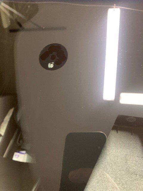
I believe those marks are from the manufacturing process. They are not holes, does not go all the way thru, at least not on my vehicle.3 points
-
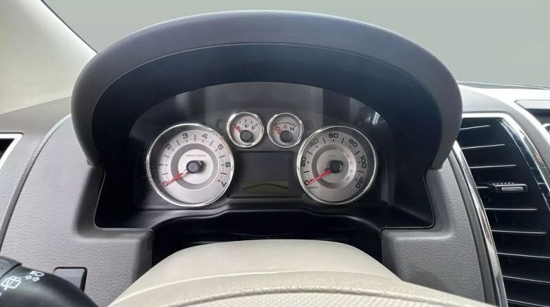
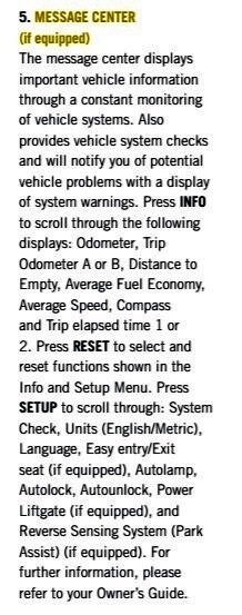
Recapping with photos: 2008 Edge Limited Instrument Cluster with Message Center digital screen... 2008 Edge Limited Instrument Panel Center Stack with Message Center control buttons, orange-boxed in this photo... Message Center Instructions on use of "Info" - "Setup" - "Reset" control buttons shown in the above photo... These instructions are contained in the 2008 Edge Quick Reference Guide, which is attached below as a PDF document... Good luck! 2008 Edge Quick Reference Guide 1st Ed.pdf
 3 points
 -
In the instructions, I assume for my 24 Nautilus Hybrid, I just push start button without pushing the brake so it is in full accessory mode.3 points
-
Thought I'd share a warranty experience that might help others on the forum. I recently had a service issue where I was out of warranty coverage based on years, but under on mileage. I informed the Service Advisor that I planned on engaging Ford Customer Service on some possible "goodwill" since I've had success with other OEMs on this. Out of this discussion, the Service Advisor and Service Manager took this up on my behalf, noting that Ford offers "After Warranty Assistance" for up to 7 years from the vehicle delivery date. Basically, if you fall into a situation like this, Ford can review the issue, along with taking into account your vehicle purchase history, service history, etc. and come up with a customer "score". Based on your score, they may offer assistance (i.e. reduce the repair cost). For my particular situation, Ford covered 40% of the repair. I'm not sure this type of assistance is always available, but if you find yourself in a similar situation, you might initiate a nice, polite, respectful discussion with your Service Advisor to see if your situation might qualify. It never hurts to ask! Good Luck!3 points
-
@enigma-2 @Wubster100 @Haz New Motorcraft battery installed 1 yr ago. So, low CCAs possible, but Ford ran diagnostics and didn't note it as an issue. As I noted in an earlier post, I was out of warranty on years, but under on mileage. I informed the Service Advisor that I planned on engaging Ford Customer Assistance regarding some potential "goodwill", and before I knew it, they took this up on my behalf. They told me that "After Warranty Assistance" is available up to 7 years from the vehicle delivery date. Ford runs through a calculation looking at your vehicle purchase history, service history, etc. and that produces an assistance number. For this repair, Ford offered to pay 40% of the total. I took that as a win!3 points
-
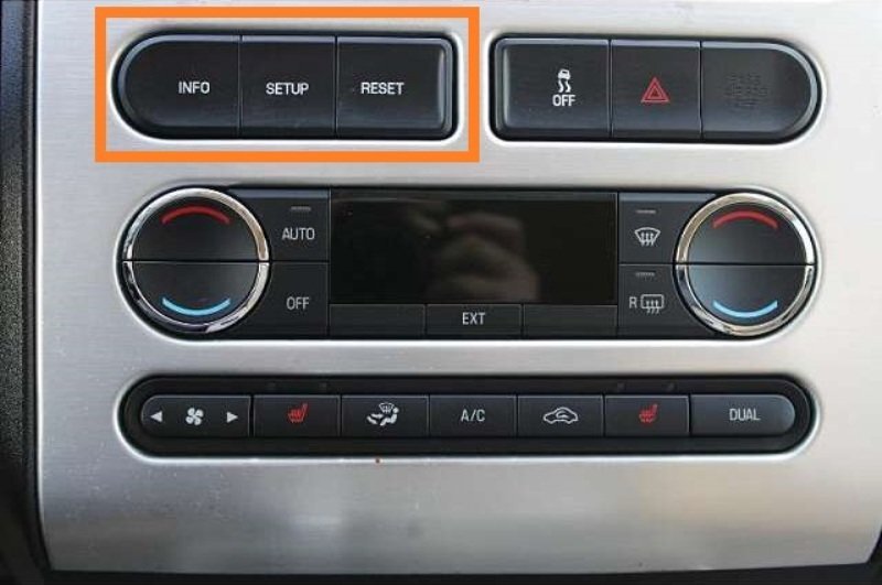
2021 they deleted the chrome tip exhaust for SE and SEL, so the tailpipes are expected. However that valance/trim shouldn't have the exhaust cut outs, it should be straight across the bottom. None of the media site or brochures show anything but Titanium or ST, so no good Ford official views of the SE/SEL. It likely has been replaced for some reason, could be just it was damaged, or there was more extensive work done. This is what it should look like:3 points
-
Just received power up update 6.2.0 yesterday afternoon3 points
-
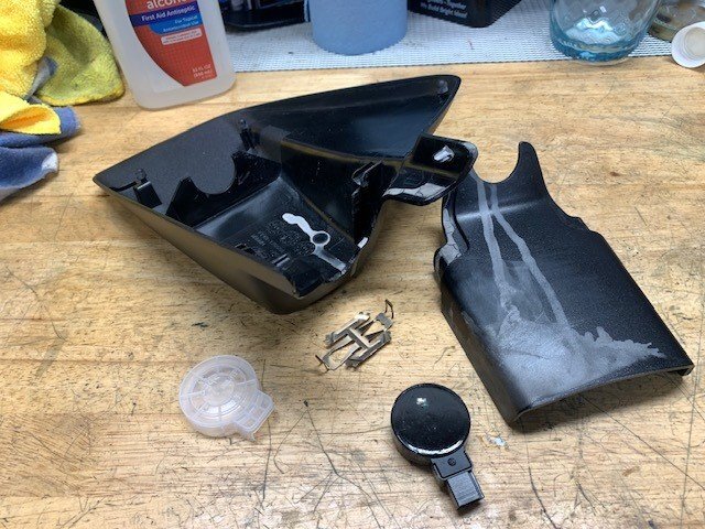
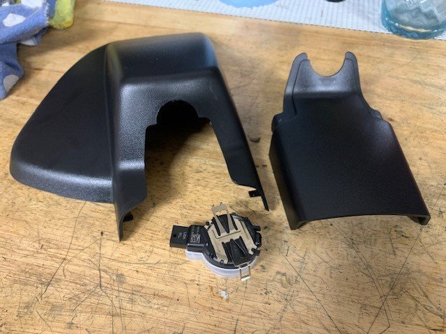
Looks like USPS is on a go slow strike in my area - takes about a week to get past my local distribution center which up until now was one day, max two days. Installed last night and its back to normal operation. The butchered plastic covers also have some odd grey bonding which must have been done by SafeLite. Unlike some of the YT videos I've seen, the gel actually covers the lens, and the gel on the old one was covered in dust/debris.

 3 points
 -
The ST doesn't have the 8F35 (it is the 8F57). That linked document is about a reprogram, that doesn't skip a gear. Only the 2021+ ST is programmed to skip 2nd gear, effectively making it a 7 speed transmission. The gear ratios between the 8F35 and 8F57 are different.3 points
-
Often times the ads for these have nonsensical details. Most of that doesn't make sense, or all of them have it. Dual shift? Could be Sport mode, could be AWD with paddle shifters). Name any vehicle in the US that doesn't have power steering! Those wheels, with the painted front and side facia with chrome means it is a Titanium 301a with the Elite Package (and it has enhanced active park assist, front camera, pano roof since no side roof rack bars, etc etc etc). You can find the brochure or order guide for it as well to determine what it really has. The wheels are 20's, if it is AWD you can go down to an 18 inch wheel (as long as it is the right backspacing and not weird, you can get standard Edge 18s for example).3 points
-
Yes, it has been requested before, probably enough difference (SYNC 4, ST 7 speed)? Or just do 2019-2024 Edge and 2024+ Nautilus? Do you want to know about 2021 Edge in general (https://cdn.dealereprocess.org/cdn/brochures/ford/2021-edge.pdf) or what might have changed from 2020 and what options your 2021 SEL might have (https://media.ford.com/content/dam/fordmedia/North America/US/product/2021/edge/2021-Edge-Order-Guide.pdf) or an overview with some details https://media.ford.com/content/fordmedia/fna/us/en/products/crossovers---suvs/edge/2021-edge.html Or post questions in the 2019-2020 Edge, which is pretty similar to 2021 (SEL lost some features)3 points
-
I would take it back to the place that did the oil change and have them find out what happened. I had something similar happen to my old Dodge Charger, and it turns out they messed up the seal when putting on the oil filter. I had oil all over my engine, hood, firewall, pretty much the whole front end of my car. They fixed the oil filter, did a thorough check to make sure nothing else got screwed up as a result, and then had the whole car detailed, including the engine compartment, and underside of the car.3 points
-
From the 2024 Nautilus Workshop Manual... Good luck! Trusted Real-Time Operation Network (TRON) - System Operation and Component Description Overview Trusted Real-Time Operation Network (TRON) is a cyber security protocol applied to certain modules connected to the vehicle communication networks. This protocol provides a digital message authentication for data being communicated between modules on the networks, to make sure the data received by a module is the data sent by the sending module and has not been interrupted or tampered with by an outside source. Trusted Real-Time Operation Network (TRON) Trusted Real-Time Operation Network (TRON) secret data authentication security keys are applied to modules with motion control, safety critical and security critical functions. Not all modules on the vehicle will have data authentication security keys applied. The secret authentication security keys provide a digital data handshake between the sending module and the receiving module to confirm the data received has been sent by the expected source. The initial secret authentication security key distribution takes place at the end of the production line, prior to the vehicle release to the dealer. The key update mechanism includes a key management client and key management server modules. The key management client is the GWM and the key management server modules are the modules participating in the TRON function. The GWM generates the keys and distributes them to itself and the server modules, one module at a time sequentially. The keys are processed by the receiving modules and stored in their memory and a backup of the distributed keys is stored in the TCU . After the vehicle's TRON has been successfully configured, the production line end of line tool sends a copy to the Ford backend data systems for storage. If a TRON-capable module is replaced, the module secret authentication security key must be applied to the new module so it functions on the network when installed. When replacing a TRON capable module, run the FDRS Trusted Real-Time Operation Network (TRON) Module Authentication Diagnosis and Repair procedure to distribute a new set of secret authentication security keys to all TRON-capable modules. The GWM and the TRON capable modules can set Diagnostic Trouble Codes (DTCs) if the keys are misaligned between modules, there are communication issues on the vehicle network or a module is not responding. Component Description Gateway Module The GWM acts as the key management client for the Trusted Real-Time Operation Network (TRON) system for creating, monitoring and distributing the secret keys to the participating modules. Telematic Control Unit Module The TCU stores a backup of all Trusted Real-Time Operation Network (TRON) distributed keys.3 points
-
Per your final comment, the Hybrid Nautilus does, in fact, utilize the High Voltage battery pack to service the 12-volt battery and low-voltage vehicle systems. Excerpts from the 2024 Nautilus Workshop Manual, with relevant Workshop Manual sections attached below as a PDF documents... Good luck! High Voltage Battery The high voltage battery consists of cells packaged into modules which deliver approximately 260 volts DC to the high voltage system. The high-voltage DC electrical power is converted to low voltage DC electrical power through the Direct Current/Direct Current (DC/DC) converter control module. This low-voltage high current DC electrical power is then supplied to the 12-volt batteries through the low voltage battery cables. Direct Current/Direct Current (DC/DC) Converter Control Module The DCDC is an liquid-cooled component that converts high voltage DC power to low-voltage (12-volt) DC power. The converter provides power to the vehicle 12-volt battery and low-voltage electrical systems. The PCM requests the DCDC to enable power conversion through an enable message over HS-CAN . The PCM sends a charging voltage setpoint request over HS-CAN to the DCDC . DCDC Operation The DCDC is responsible for maintaining and charging the 12-volt battery. The DCDC is protected by a 50 amp high voltage low current fuse located in the high-voltage BJB . The DCDC steps the high-voltage down to a low-voltage (between 12.0 and 15.5 volts, depending on vehicle needs), providing power to the vehicle low-voltage battery systems. Depending on the vehicle and environmental conditions, the DCDC is capable of outputting up to 260 amps to the 12-volt battery. High Voltage Battery, Mounting and Cables - System Operation and Component Description - 2024 Nautilus Workshop Manual.pdf DCDC Converter Control Module - System Operation and Component Description - 2024 Nautilus Workshop Manual.pdf Climate Control System - System Operation and Component Description - 2024 Nautilus Workshop Manual.pdf3 points
-
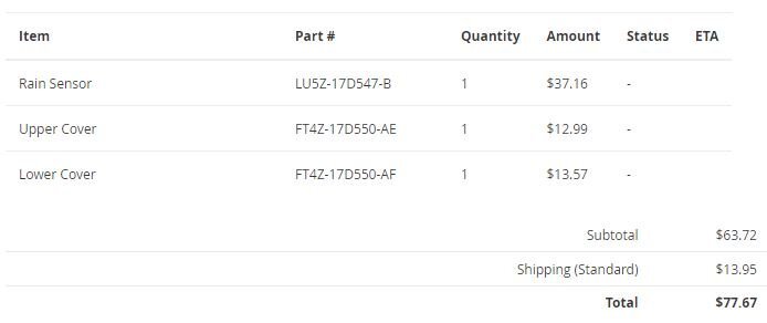
Parts ordered - will be a project for the weekend of 1/25 I added the two covers because SafeLite and RiteWay installers butchered them. Lesson to others, when you have a windshield replacement make sure its OEM glass and not a Chinese knock-off, and make sure all related functions such as lane guidance and rain sensing is in 100% working order. .
 3 points
 -
I too had this rattle in my 2020 ST .. my fix was to take a piece of a tactical belt which is a little heavier and thicker than the Velcro … lift up on that spring loaded clip and place this piece under the clip that rest on the rail.. perfect fix been like this for about two months works without out fail … no noise or rattling3 points
-
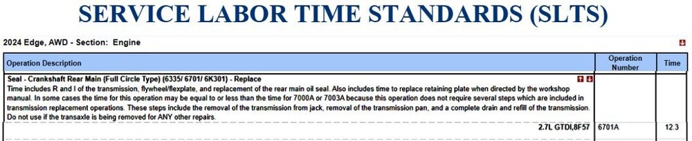
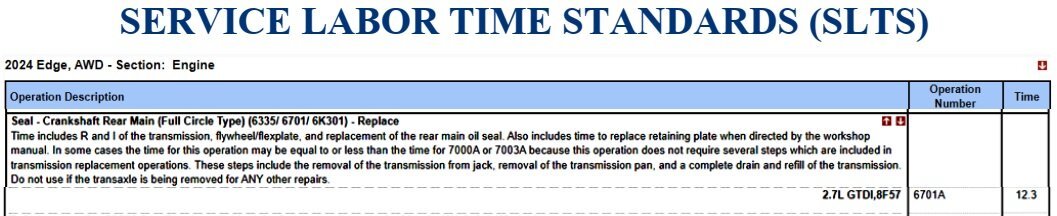
SSM 53292 - 2018-2025 Various Vehicles - 2.7/3.0L EcoBoost - Engine Oil Leak From The Crankshaft Rear Seal With Retaining Plate Some 2018-2024 F-150/Edge, 2018 MKX, 2019-2023 Nautilus, 2020-2025 Explorer/Aviator, 2021-2024 Bronco, and 2024 Ranger vehicles equipped with a 2.7L or a 3.0L EcoBoost engine may exhibit an engine oil leak from the crankshaft rear seal with retaining plate. If diagnostics lead to the replacement of the crankshaft rear seal with retaining plate, the crankshaft rear seal with retaining plate has been updated for improved sealing performance. Replace the crankshaft rear seal with retaining plate with the updated part (JT4Z-6335-C) or latest level part. Refer to the Workshop Manual (WSM), Section 303-01. For claiming, use causal part 6335 and applicable labor operations in Section 06 of the Service Labor Time Standards (SLTS) Manual. The referenced Workshop Manual section is attached below as a PDF document... Crankshaft Rear Seal with Retainer Plate - 2.7L EcoBoost - Removal and Installation - 2022-2024 Edge Workshop Manual.pdf
 3 points
 -
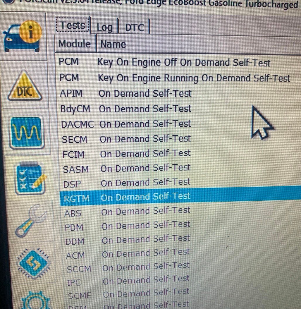
I just went out and tried the same, I think it is improved, should have measured it to be 100% sure. I am 6' tall and now when open tailgate barely touches my head from the sides of the latch area, however, the latch itself still hits my head. Also, I could still raise it by hand another 1.5"-2". I tried to reboot the module using ForScan while the tailgate was fully open, but this made it think it closed, pressing any button to close the tailgate just caused the latch to make a sound like it's trying to unlock without any movement. Had to close it by hand for it to then function normally.3 points
-
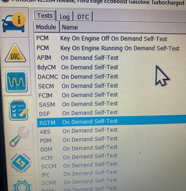
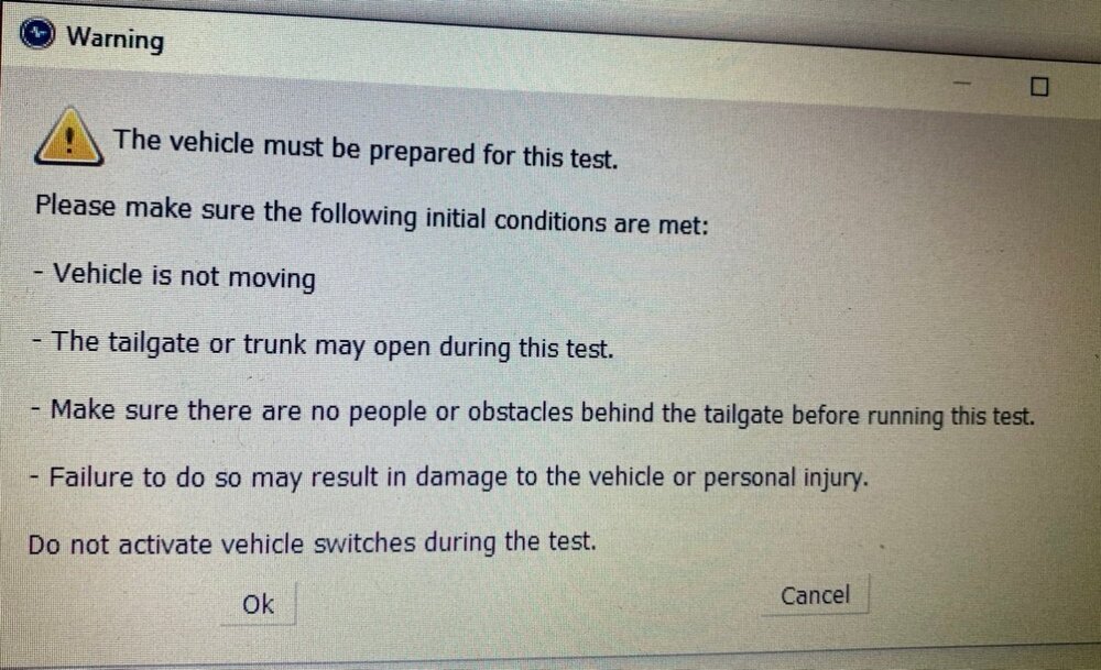
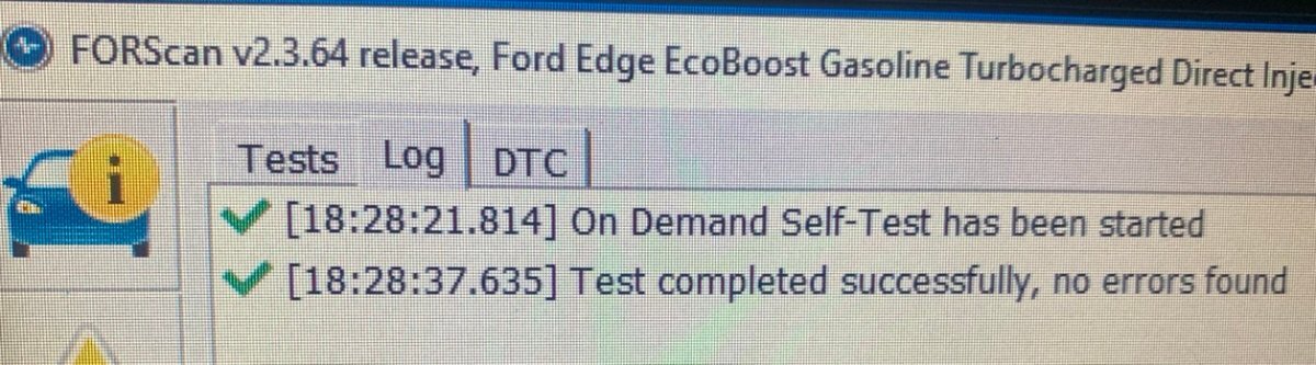
As I was getting set up with my laptop to follow the above instructions when I noticed the "RGTM On-Demand Self-Test", so I thought lets try this and it worked. As the test ran it drove the tailgate full open, but being at the drivers seat I wasn't sure of what I saw, so repeated the test and yes it went full open - then I tried the buttons and they too took it wide open - wide open is where its staying seeing as there's more than adequate clearance to by open garage door. Thanks everyone - I didn't need to spend a dime !!!

 3 points
 -
Welcome to the Forum @ArtdW! Two suggestions from the 2013 Edge Workshop Manual's Engine Noise Vibration Harshness (NV) Symptoms Chart... Engine and transaxle mount images from 2013 Edge Workshop Manual... Remove the transaxle support insulator through bolt and nut. Remove the 3 nuts, the bolt and the transaxle support insulator bracket. Remove the nut, bolt and engine mount brace. Remove the 4 engine mount nuts. Flexplate Inspection procedure from the 2013 Edge Workshop Manual, and Technical instructions from a 2015-2018 2.0L EcoBoost Flexplate cracks inspection Customer Satisfaction Program are attached below as PDF documents... While the Customer Satisfaction Program does not apply to your Edge, due to its model year and its 3.5L Duratec, the technical instructions' imagery and inspection method description may be helpful. Based upon the symptom in the video, and your impression that the noise is coming from the back of the engine, you may want to use a borescope to inspect the Flexplate for cracks. Good luck! Flexplate Inspection - General Procedures - 2013 Edge Workshop Manual.pdf Customer Satisfaction Program 22N12 - 2015-2018 MY 2.0L EcoBoost - Flexplate Inspection Technical Instructions.pdf


 3 points
 -
This was all done at the dealership. Been using them for 7+ yrs now yea you pay a bit more but it's done right well worth it.3 points
-
@al303: To emphasize the importance of your Health and Safety awareness, the SRS Depowering and SRS Repowering procedures are included here and are also provided below as PDF documents, as is a general Pyrotechnic Device Health and Safety Precautions document... Work safely! Supplemental Restraint System (SRS) Depowering - General Procedures - 2018 Edge Workshop Manual.pdf Driver Airbag - Vehicles With Adaptive Steering - Removal and Installation - 2018 Edge Workshop Manual.pdf Pyrotechnic Device Health and Safety Precautions - General Procedures - 2018 Edge Workshop Manual.pdf Battery Disconnect and Connect - General Procedures - 2018 Edge Workshop Manual.pdf Supplemental Restraint System (SRS) Repowering - General Procedures - 2018 Edge Workshop Manual.pdf Adaptive Steering - SECM Wiring Diagram - 2018 Edge.pdf STEERING EFFORT CONTROL MODULE (SECM) - Connectors C2391A, C2391B, C2391C Location - 2018 Edge.pdf STEERING EFFORT CONTROL MODULE (SECM) - Connectors C2391A Pinout - 2018 Edge.pdf STEERING EFFORT CONTROL MODULE (SECM) - Connectors C2391B Pinout - 2018 Edge.pdf STEERING EFFORT CONTROL MODULE (SECM) - Connectors C2391C Pinout - 2018 Edge.pdf CLOCKSPRING-STEERING ANGLE SENSOR MODULE (SASM) - Connector Locations - 2018 Edge.pdf STEERING EFFORT CONTROL MODULE (SECM) - Ground G200 Location - View #1 - 2018 Edge.pdf STEERING EFFORT CONTROL MODULE (SECM) - Ground G200 Location - View #2 - 2018 Edge.pdf Steering Column Shrouds - Removal and Installation - 2018 Edge Workshop Manual.pdf
Depowering-GeneralProcedures-2018EdgeWorkshopManual.thumb.jpg.a88cf6661fc06b9cf96b7543efde2681.jpg)
Repowering-GeneralProcedures-2018EdgeWorkshopManual.thumb.jpg.b60bd7d8858304d84fd413e40d64e3be.jpg) 3 points
3 points -
@al303: Excerpts from 2018 Edge Workshop Manual, with emphasis added, and full sections attached below as PDF documents... Placing your device cursor over underlined acronyms may yield full-words descriptions of the acronyms. Adaptive Steering Overview The adaptive steering system provides steering assist to the driver by dynamically changing the steering ratio between the steering wheel and the road wheels, thereby reducing the number of steering wheel turns required to turn the road wheels. This is accomplished through the use of a motor, worm gear and toothed hub. All adaptive steering system components are inside the steering wheel, behind the driver air bag. Adaptive Steering System The SECM is self-monitoring and is capable of setting and storing Diagnostic Trouble Codes (DTCs). Depending on the nature of the DTC , the SECM may engage the adaptive steering lock and may send a request to the IPC to illuminate the adaptive steering system warning indicator and display a message in the message center alerting the driver of a potential adaptive steering system concern. The warning message is sent over the HS-CAN2 to the GWM where it is converted to a HS-CAN3 message and forwarded on to the IPC over the HS-CAN3 . Adaptive Steering Lock The adaptive steering system is designed with a locking device. While the lock is engaged, the steering system is set to a fixed (1:1) steering ratio. A sound may be heard when the vehicle is started or shut off as the lock is disengaged or engaged and a slight movement of the steering wheel may be noticed while the locking action is taking place. If the vehicle loses electrical power or the SECM detects a fault while driving, the lock is engaged. Extreme operating conditions may also cause the SECM to engage the lock. This strategy prevents overheating and permanent damage to the adaptive steering system. Typical steering and driving maneuvers allow the system to cool and return to normal operation. While the lock is engaged, it is possible the steering wheel may not be straight when the vehicle is driving straight ahead and the driver may notice the steering wheel angle or "clear vision" may be off-set. The locking solenoid also engages when the ignition is set to ON and the driver door is closed, this prevents the steering wheel from turning unnecessarily while the system is off and affecting steering wheel clear vision. The locking solenoid disengages once the engine is started. Adaptive Steering System - Diagnosis and Testing PINPOINT TEST K: STEERING LOCK CONCERN Introduction Normal Operation and Fault Conditions With the ignition ON, the SECM monitors various inputs to detect if a fault is present. DTC Fault Trigger Conditions DTC Description Fault Trigger Condition C1039:7F Active Front Steering (AFS) Lock: Actuator Stuck Off Sets when the SECM cannot activate the adaptive steering lock at engine start. C1039:92 Active Front Steering (AFS) Lock: Performance Or Incorrect Operation Sets when the SECM detects the adaptive steering lock fails the unlocking test. C1039:94 Active Front Steering (AFS) Lock: Unexpected Operation Sets when the SECM detects the adaptive steering lock fails the integrity test or the locking disc calibration test. C200D:28 Motor Rotation Angle Sensor: Signal Bias Level Out Of Range/Zero Adjustment Failure Sets when the SECM detects the adaptive steering motor angle sensor signal is outside the normal operating range or if the sensor is incapable of learning the center position. C200D:62 Motor Rotation Angle Sensor: Signal Compare Failure Sets when the SECM detects the adaptive steering motor angle sensor fails to learn the center position. U2001:92 Reduced System Function: Performance Or Incorrect Operation Sets due to a restraint airbag impact event or a fuel cutoff event. Due to the fault setting conditions, the installation of a new steering wheel and SECM are not covered under the vehicle warranty. Subsequently, a RVC is not provided for component replacement due to this DTC. U3000:46 Control Module: Calibration/Parameter Memory Failure Sets when the SECM detects an internal fault. U3000:49 Control Module: Internal Electronic Failure Sets when the SECM detects an internal fault. U3000:61 Control Module: Signal Calculation Failure This DTC sets due to an incomplete or an improperly performed trim routine. U3000:9A Control Module: Component or System Operating Conditions Sets when the SECM detects an internal fault. Possible Causes Incorrect sensor input SECM (steering wheel) K1 CARRY OUT THE SASM (STEERING ANGLE SENSOR MODULE) MODULE RESET ROUTINE NOTE: If present in any module, diagnose DTC U3003:16, U3003:1C or U3003:68 before diagnosing DTC C1039:7F, C1039:92 or U3000:49. Ignition ON. Using a diagnostic scan tool, carry out the SASM Module Reset routine. No VCM Recognized Ignition OFF. Start the engine and wait 20 seconds for the SECM to wake up and test the adaptive steering system. Ignition ON. No VCM Recognized Is the original DTC from the DTC Fault Trigger Conditions table retrieved again? Yes GO to K2. No For all other DTCs , REFER to the SECM DTC Chart. If no DTCs are present, the concern is not present and the system is operating correctly at this time. K2 CHECK FOR SASM (STEERING ANGLE SENSOR MODULE) DTCS No VCM Recognized Are any SASM DTCs present? Yes DIAGNOSE the DTCs present. REFER to Section 206-09 in the Workshop Manual. No GO to K3. K3 VERIFY ALL WIRING CONNECTIONS Ignition OFF. Disconnect all SECM electrical connectors. Using a good light source, inspect all disconnected electrical connectors for the following: corrosion - install new connector or terminal and clean the module pins damaged or bent pins - install new terminals or pins pushed-out pins - install new pins as necessary spread terminals - install new terminals as necessary Are the connectors free of corrosion, damaged pins, bent pins, pushed-out pins and spread terminals? Yes For all others: GO to K4. No REPAIR the connector or terminals. Refer to Wiring Diagrams Cell 5 for schematic and connector information. K4 CHECK FOR CORRECT SECM (STEERING EFFORT CONTROL MODULE) OPERATION Connect all SECM electrical connectors. Make sure they seat and latch correctly. Operate the system and determine if the concern is still present. Is the concern still present? Yes INSTALL a new Steering Wheel (SECM) assembly. CHECK OASIS for any applicable service articles: TSBs , GSB, SSM#2 or FSA. If a service article exists for this concern, DISCONTINUE this test and FOLLOW the service article instructions. If no service articles address this concern, INSTALL a new SECM (part of the steering wheel). REFER to Section 211-04 in the Workshop Manual. Generate RVC only works in single-step view No The system is operating correctly at this time. The concern may have been caused by a loose or corroded connector. ADDRESS the root cause of any connector or pin issues. K5 CHECK FOR CORRECT SECM (STEERING EFFORT CONTROL MODULE) OPERATION Connect all SECM electrical connectors. Make sure they seat and latch correctly. Operate the system and determine if the concern is still present. Is the concern still present? Yes INSTALL a new Steering Wheel (SECM) assembly. CHECK OASIS for any applicable service articles: TSBs , GSB, SSM#2 or FSA. If a service article exists for this concern, DISCONTINUE this test and FOLLOW the service article instructions. If no service articles address this concern, INSTALL a new SECM (part of the steering wheel). REFER to Section 211-04 in the Workshop Manual. No The system is operating correctly at this time. The concern may have been caused by a loose or corroded connector. ADDRESS the root cause of any connector or pin issues. If you're inclined toward fuller do-it-yourself efforts to resolve the issue, I can provide additional procedures and resources, otherwise this provides you a glimpse at what a professional technician at the dealership or an independent repair facility may be considering. Link to this FordParts webpage Good luck! Adaptive Steering - Overview - 2018 Edge Workshop Manual.pdf Adaptive Steering - System Operation and Component Description - 2018 Edge Workshop Manual.pdf PINPOINT TEST K - STEERING LOCK CONCERN - Diagnosis and Testing - 2018 Edge Workshop Manual.pdf Steering Wheel - Vehicles With Adaptive Steering - Removal and Installation - 2018 Edge Workshop Manual.pdf3 points
-
Agree, if those were holes, you'd have an issue going through a car wash - drain holes are typically at a low point and protected against water jets.2 points
-
The administrators finally responded and created the subsection - 2019-Current Edge & Nautilius2 points
-
I have a 2019 Edge ST with 82k. It has the factory Class II hitch. We winter in SC (from southern MI) and this year I wanted to bring my motorcycle in a trailer. Rentals proved to be overly expensive so I picked up a 6x10 Cross enclosed trailer. The trailer is 1350lbs, and my bike is 550lbs. Add in some tools and other stuff, its close to 2,000 lbs. Towing capacity is 3500 lbs. The Edge performed great. On the first leg of the trip, I left the trans in D mode and it felt sluggish as well as a first stop fuel mileage of 14.3. I switched to Sport mode and the motor really comes to life with improved power and delayed shifts. This was especially useful in the mountains of southern Ohio, West Virginia and Virginia. I let the tranny shift automatically in Sport mode and mileage improved to about 16. Overall, very happy with its performance.2 points
-
Generally I use OEM but for this being a non critical device and two OEM ones didn't last as long as I'd expect, I went with the DORMAN 994073 at around half the price from RockAuto.com.2 points
-
Thanks for the info I will be able to pull codes tomorrow when USB dongle shows up for forscan and have the new battery load tested. I did check fuse 11 and has 12.7v ignition on, 14v+ engine running. I checked the Blue/Red wire at IPC and have 12.7v, ground tests good continuity to steering column. I did leave battery disconnected for a few hours, tried BMS reset but with no cluster I dont know if it did anything, also let it sit a few days untouched and off for the 8 hour reset. Ill post what forscan shows once I can hook that up. Glad I am at least looking down the right path will know more when im back in town.2 points
-
From the 2021 Edge Workshop Manual, attached below as PDF documents... Good luck! Accessory Protocol Interface Module (APIM) - Removal and Installation - 2021 Edge Workshop Manual.pdf Center Display Screen - Removal and Installation - 2021 Edge Workshop Manual.pdf2 points
-
I have a 2024 ST and here are few things I can say. In 21 they went to the bigger touchscreen (sync 4) which is kind of game changer. The navigation screen is awesome! I got the 401A package which gave me the sunroof and heated seats/steering wheel. I have gotten spoiled the heated steering wheel for sure. I did get the performance brake and tire package which is great because you get the bigger calipers and rotors. The only issue is they come (only) with summer tires which work good for where I live, but not good in your climate. They should offer that package with a few different tire options, but they don't. Also, in 21 they went to a 7-speed transmission (via programming) and helps with the performance. I drove both and the 7 speed is an improvement. Hope some of this helps.2 points
-
I have a 2021 SEL. I think the reason is because the owner of the forum is gone or something like that. https://www.fordedgeforum.com/topic/27032-ford-edge-forum-what-happened/2 points
-
Thanks - we already changed the cabin air filter, we could do that just by dropping the front of the glove box. I really appreciate your input and help. You have no idea how much that clicking noise bothered me. Now my car is nice and quiet.2 points
-
@conniepj: In the future, if you wish to change the Cabin Air Filter, that does require removal of the Glove Box, per the attached Workshop Manual procedure... Good luck! Cabin Air Filter - Removal and Installation - 2018 Edge Workshop Manual.pdf2 points
-
@omar302: Oil Pan removal & installation and related supporting procedures from the 2016 Edge Workshop Manual are attached below as PDF documents... Good luck! Oil Pan - Removal and Installation - 2.7L EcoBoost - 2016 Edge Workshop Manual.pdf RTV Sealing Surface Cleaning and Preparation - General Procedures - 2016 Edge Workshop Manual.pdf Catalytic Converter LH - Removal and Installation - 2.7L EcoBoost - 2016 Edge Workshop Manual.pdf Air Conditioning (A-C) Compressor - Removal and Installation - 2.7L EcoBoost - 2016 Edge Workshop Manual.pdf Exhaust Flexible Pipe - Removal and Installation - 2.7L EcoBoost - 2016 Edge Workshop Manual.pdf Fender Splash Shield - Removal and Installation - 2016 Edge Workshop Manual.pdf Engine Oil Draining and Filling - General Procedures - 2.7L EcoBoost - 2016 Edge Workshop Manual.pdf Accessory Drive Belt - Removal and Installation - 2.7L EcoBoost - 2016 Edge Workshop Manual.pdf2 points
-
Link to this FordParts webpage Service Labor Time Standards (SLTS) Good luck!
-H2GZ14B321A-FordParts_com.thumb.jpg.f65f7f0ee5e26e69f3fb4197fb4f6bb4.jpg)
-ServiceLaborTimeStandards(SLTS).jpg.adadd421214df5dc9f3bac7b79c46f69.jpg) 2 points
2 points -
Yes that is right. You are only supposed to reset the BMS after the 12v battery has been replaced.2 points
-
Welcome. I found the info and video posted in this thread is more than adequate for the replacement - what specifically do you mean by "the ones above dont seem to work" ? Have you actually tried it and if so what part of the process are you having difficulty with?2 points
-
A few updates to the cruise control project: 1. I have not replaced the lower front bumper cover trim to one that protects the cruise control module. So far, no damage or sensor blockage has occurred. I was able to use adaptive cruise control in the rain. I did not notice any snow or dirt accumulate on the sensor. 2. The ABS module will need to be replaced for lane centering, evasive steering assist, and ACC to 0 mph. I have received an ABS module. Currently, FORScan does not have any ABS service functions for the 2021-2024 Edge. However, the FORScan Team has sent me a test build, so I should be able to calibrate the ABS module and bleed the brakes. Hopefully I will be able to find time to replace the ABS module and bleed the brakes soon. 3. A little while ago, my ACC and pre collision assist stopped working. The cause of this problem was a poor connection (done by me lol). The CCM was only getting about 8 volts of power. The solution to this was to fix my bad wiring and ensure the CCM communication wires are a twisted pair.2 points
-
Welcome to the Forum @Got 2! From the 2020 Edge Workshop Manual... Good luck! Loadspace Trim Panel - Removal and Installation - 2020 Edge Workshop Manual.pdf2 points
-
One possible issue it might be is the so called "coolant intrusion" issue. You don't mention your coolant level going down or needing to add some or frequently, but it is possible that is the issue, or seeing white "smoke" (actually steam) from the tailpipes. The spark plug from that cylinder would have looked different, probably lacking carbon or maybe orange/yellow tinged from the coolant. https://static.nhtsa.gov/odi/tsbs/2019/MC-10169807-0001.pdf2 points
-
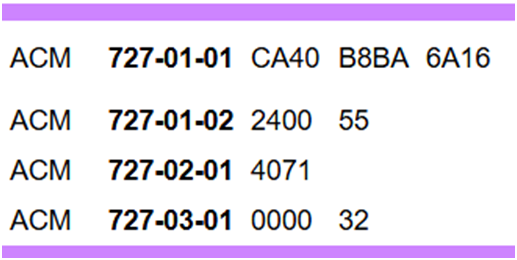
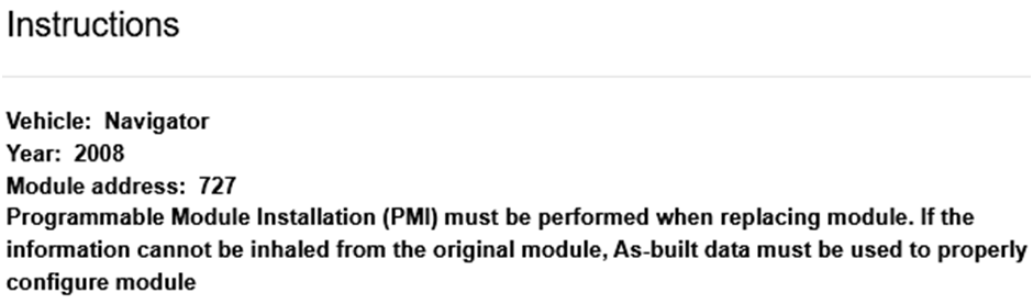
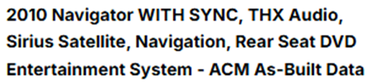
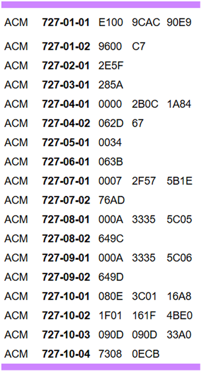
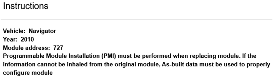
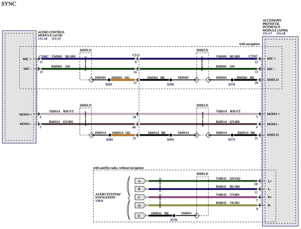
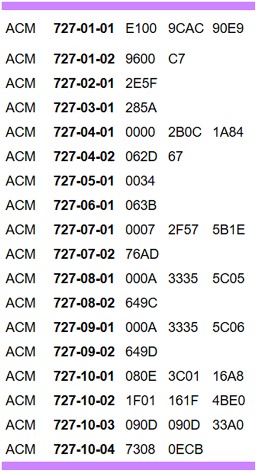
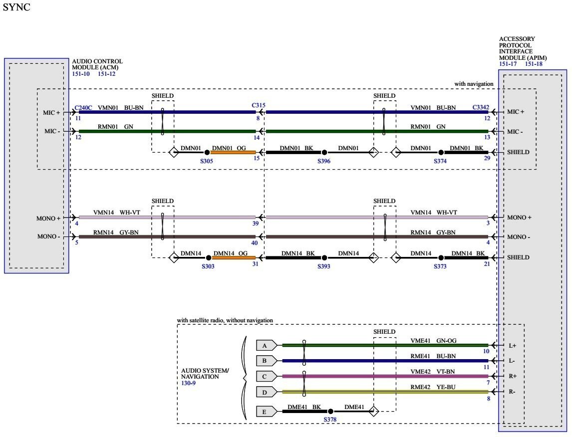
The Ford Expedition Forum is a community of experienced and helpful Expedition & Navigator owners that you may enjoy -- but a long as you're here: Per the Expedition-Navigator Workshop Manual, with emphasis added, the Audio Control Module (ACM) is a configurable component... Principles of Operation Configurable modules accommodate a variety of vehicle options, eliminating the need for many unique modules for one vehicle line. These modules must be configured when replaced as part of a repair procedure. Configurable modules should not be exchanged between vehicles since the settings are unique to each vehicle. Failure to configure a new module may result in improper operation and/or Diagnostic Trouble Codes (DTCs) setting. As-Built Data As-Built data is a VIN specific module configuration record. During vehicle build, the configuration from all modules is downloaded and stored in the As-Built database. NOTE: It is not necessary to obtain As-Built data unless directed to do so by the scan tool. This data may be accessed from the technician service publication website. As-Built datasets for Ford-Lincoln-Mercury vehicles from 1999 to current model years can be obtained from the Ford Service Info website (link), where the user selects and submits Country and Language, and then enters and submits the vehicle's VIN on the next webpage. As-Built data is presented in text format as well as an electronic .ab-format downloadable file. As-Built data for the ACM is contained in Line 727 entries, which are among configuration data for all other of the vehicle's configurable modules. It's worth noting that 2008 Navigators are not equipped with SYNC -- which was introduced on the 2009 Navigator -- so looking at ACM As-Built configuration values for 2008 versus 2010 Model Years reveals a significant difference because of the 2010 ACM's added interaction with the vehicle's SYNC (APIM) Module. Be aware that your 2008 ACM values may not be the same as this VIN-specific 2008 ACM As-Built example... It's likely that your 2010 ACM has set Diagnostic Trouble Codes (DTCs) after its installation in your 2008 Navigator, due to the 2010 ACM looking for -- and not finding -- the expected SYNC (APIM) Module. If the 2010 ACM is returnable, then you may choose send it back because of it's SYNC-capability which your 2008 Navigator lacks. If you cannot return the 2010 ACM, then it may be worth obtaining the As-Built configuration values for your 2008 ACM, either from the module itself using a Scan Tool or Forscan on a device connected to your Navigator's OBDII data port, or, by downloading your Navigator's As-Built dataset from the Ford Service Info site. Then, reprogram the 2010 ACM Line 727 values which correspond to your 2008 Navigator ACM's Line 727 values using a Scan Tool or a device containing a licensed version of Forscan capable of module programing via your Navigator's OBDII data port. Doing this may or may not enable the 2010 ACM to produce joyful noise in your Navigator. Good luck!


 2 points
 -
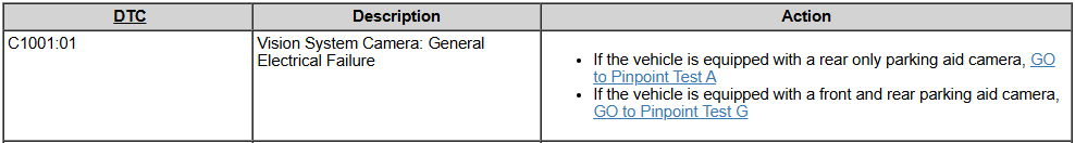
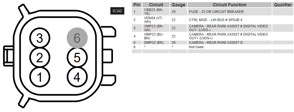
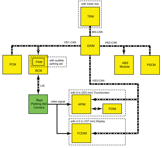
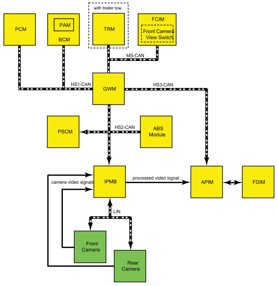
Welcome to the Forum @rdavis006! Echoing @Wubster100, from the 2016 Workshop Manual's final step of the Rear Camera installation procedure: Follow the instructions on the scan tool to configure the rear view camera. If Rear Only Parking Aid Camera LIN Communication The BCM and the rear parking aid camera communicate via a LIN circuit which is a dedicated single wire communication network. The messages sent from the BCM to the camera are: Camera configuration data Display manual zoom request Guideline on/off request Trailer connection status (if equipped with trailer tow) Steering angle Standby enable/disable request The messages sent from the camera to the BCM are: Camera status Display zoom status Camera part number data Guideline status If Front and Rear Parking Aid Cameras LIN Communication The IPMB communicates with the front and rear cameras via a LIN circuit, which is a dedicated single wire communication network. The messages sent from the IPMB to the front and rear cameras are: Camera view request (front camera only) Camera configuration data Display manual zoom request (rear camera only) Guideline on/off request (rear camera only) Trailer connection status (if equipped with trailer tow) Steering angle (rear camera only) Standby enable/disable request The messages sent from the front and rear camera to the BCM are: Camera status Display zoom status (rear camera only) Camera part number data Guideline status (rear camera only) Per your original request: 2016 Edge Rear Camera partial diagnostic Pinpoint Test, with connector pinout and Battery Junction Box (BJB) fuse location... DTC Charts: APIM Pinpoint Test A (Partial) A9 CHECK FOR VOLTAGE TO THE REAR CAMERA Ignition OFF. Disconnect Rear Parking Aid Camera C4357. Ignition ON. Measure: Positive Lead Measurement / Action Negative Lead C4357 Pin 1 Ground Is the voltage greater than 11 volts? Yes GO to A10 No INSPECT BJB fuse 23 (15A). If the fuse is OK, repair the circuit for an open. If the fuse is not OK, REFER to the Wiring Diagrams manual to identify the possible causes of the short circuit. A10 CHECK FOR GROUND AT THE REAR CAMERA Measure: Positive Lead Measurement / Action Negative Lead C4357 Pin 1 C4357 Pin 5 Is the voltage greater than 11 volts? Yes GO to A12 No For vehicles with an 8 in (203 mm) touchscreen, GO to A11 For vehicles with a 4.2 in (107 mm) centerstack infotainment display, REPAIR the circuit. Good luck!

-FuseF23Red-Boxed-2016Edge.thumb.jpg.99be078b9ed9993ee01455a3e1a52ee0.jpg)

 2 points
 -
You are a man after my heart! I've done this sort of stuff for a long time, a long time ago. But, there were no charts and obtaining parts from different auto manufacturers to modify to fit the current project. A real funny one was a Salesman came back and asked if I could install remote control mirrors on a 1974 Fiat 124 Spider. After a quick thought I said "Yes" and the sale went through. The mirrors came from an AMC dealership and the New Car Owner loved them! I applaud you to the MAX!2 points
-
Special Service Message 51117 - Effective October 4, 2022... SSM 51117 - 2019-2022 Various Vehicles - Illuminated All Wheel Drive (AWD) Warning Indicator Or Fault Message With Certain DTCs Some 2021-2022 Bronco Sport 1.5L, 2019-2022 Edge/Nautilus, 2020-2022 Escape/Corsair, and 2022 Maverick vehicles may exhibit an illuminated AWD warning indicator or fault message with diagnostic trouble code (DTC) C0095:71/:19 stored in the all wheel drive (AWD) module. Some 2021-2022 Bronco Sport 2.0L may exhibit an illuminated AWD warning indicator or fault message with DTC C05D9:71, C05E8:71, C05D8:19 and/or C05E7:19 stored in the AWD module. This may be due to a rear drive unit (RDU) motor magnet ring misalignment. RDU assembly replacement is no longer required. To correct the condition, replace the RDU motor which is now available separately for service. Refer to Workshop Manual, Section 205-02 for diagnosis and repair procedures. For claiming use causal part 4C210 and applicable labor operations in Section 10 of the Service Labor Time Standards (SLTS) Manual. Good luck!2 points
-
When the battery is replaced, the BMS must be reset. To reset the BMS without using a diagnostic scan tool: 1. Make sure all windows & doors are closed. 2. Turn ignition switch to on (don't start car). Wait 10 seconds. 3. Flash high beams 5 times using the "flash to pass" stalk on the side of the steering wheel (on/off, on/off, on/off, on/off, on/off). 4. Press brake pedal 3 times in 10 seconds. 5. The battery light on instrument cluster will flash indicating the BMS has been reset. Battery Replacement If the vehicle battery is replaced, it is very important to perform the battery monitoring system reset using the diagnostic scan tool. If the battery monitoring system reset is not carried out, it holds the old battery parameters and time in service counter in memory. Additionally it tells the system the battery is in an aged state and may limit the Electrical Energy Management system functions. Battery State of Charge The Electrical Energy Management system monitors the battery current flow and voltage to determine the battery state of charge. During the drive cycle the Electrical Energy Management system software monitors the charge and discharge current and increases the state of charge during charging, and decreasing it during discharge. During rest periods (key off with no electrical loads) when the vehicle enters sleep mode, the battery voltage is sampled to calibrate the state of charge. The sensor automatically executes this calibration anytime the vehicle enters sleep mode and when the total vehicle current draw is below 300mA. It takes 4 to 6 hours in the sleep mode to calibrate the battery state of charge to high accuracy. If the system draw does not allow the battery state of charge calibration over the previous 7 to 10 days the state of charge quality factor changes to flag this and some Electrical Energy Management system functions, which rely on the accuracy of the battery state of charge, may be temporarily turned off until a calibration takes place. Battery Monitoring Sensor NOTICE: Unless the battery is being replaced, DO NOT reset the battery monitoring system using the diagnostic scan tool. This reset is reserved for new battery installation only. This reset will clear the learned battery data, the battery time in service, and will affect the aging algorithm parameters, which have been learned since the installation of the battery. The battery monitoring sensor is integrated with the negative battery terminal clamp and cable assembly, which provides a ground to the sensor. The battery monitoring sensor measures voltage, current, and temperature of the battery and uses these inputs to calculate the battery condition. The sensor transmits this information through the LIN circuit to the BCM. The battery monitoring sensor has a 2-pin connector providing battery voltage and LIN connections.2 points
-
This popped up here a year or two ago. It was seen on the 2019 Edge / Nautilus in very cold weather, and caused by a software upgrade. .2 points
-
I’m a little confused about the operation of this. So if I have shut off the lane control and use the cruise control then I will not see the orange light and won’t hear the ding?2 points
-
It is definitely the lane centering. I took my Edge on a 1,000 mile roundtrip jaunt over the last 4 days with almost all freeway driving, so I used the cruise for hours at a time. A few times I heard the chime and the steering wheel was orange. Most of the time it was caused by the lane lines not marked clearly, or the sun was reflecting on the road and the camera probably couldn't get a clear image. It just seems like that's what it should do, to let you know to pay attention and seems like a good idea to me. There certainly is no malfunction.2 points
-
If your Edge is not equipped with Automatic Headlamp Leveling... The mid and high series headlamps may be equipped with automatic headlamp leveling. The headlamp beam height is automatically adjusted according to vehicle load, speed, acceleration and braking. Automatic headlamp leveling is activated when the headlamp switch is in the HEADLAMPS or AUTOLAMPS position. ...then it may be Connector C2129 for the Headlamp Control Module (HCM), which is only installed on vehicles equipped with automatic headlamp leveling... Good luck! Headlamp Control Module (HCM) - Connector C2129 Pinout - 2021 Edge.pdf
-Illustration-2021EdgeWorkshopManual.thumb.jpg.4b22832496db8b28eac4c659fae38a96.jpg)
-ConnectorC2129Location-2021Edge.jpg.afca1d8708ed061b2cc44d9e3895ba77.jpg) 2 points
2 points


Depowering-GeneralProcedures-2018EdgeWorkshopManual.jpg.d1b088ec24b713439faa49f4ac742623.jpg)
Repowering-GeneralProcedures-2018EdgeWorkshopManual.jpg.f6f24d3797cf8b72aaba62dbcceb185c.jpg)
-H2GZ14B321A-FordParts_com.jpg.d4fd792913c85d6eeb7b062a80fb7f85.jpg)
-FuseF23Red-Boxed-2016Edge.jpg.cdc255582157973b2576e6b6afc47d7d.jpg)

-Illustration-2021EdgeWorkshopManual.jpg.e75b7c476e0ead894a367303618f8da4.jpg)